SlideShare a Scribd company logo
1
INTRODUCTION TO POWER PLANTS
STEAM POWER PLANTS:
A thermal power station is a power plant in which the prime mover is steam driven.
Water is heated, turns into steam and spins a steam turbine which drives an electrical generator.
After it passes through the turbine, the steam is condensed in a condenser and recycled to where
it was heated; this is known as a Rankine cycle. The greatest variation in the design of thermal
power stations is due to the different fuel sources. Some prefer to use the term energy center
because such facilities convert forms of heat energy into electricity. Some thermal power plants
also deliver heat energy for industrial purposes, for district heating, or for desalination of water
as well as delivering electrical power. A large proportion of CO2 is produced by the worlds
fossil fired thermal power plants; efforts to reduce these outputs are various and widespread.
LAYOUT OF STEAM POWER PLANT:
The four main circuits one would come across in any thermal power plant layout are
- Coal and Ash Circuit
- Air and Gas Circuit
- Feed Water and Steam Circuit
- Cooling Water Circuit
2
Coal and Ash Circuit
Coal and Ash circuit in a thermal power plant layout mainly takes care of feeding the
boiler with coal from the storage for combustion. The ash that is generated during combustion
is collected at the back of the boiler and removed to the ash storage by scrap conveyors. The
combustion in the Coal and Ash circuit is controlled by regulating the speed and the quality of
coal entering the grate and the damper openings.
Air and Gas Circuit
Air from the atmosphere is directed into the furnace through the air preheated by the
action of a forced draught fan or induced draught fan. The dust from the air is removed before
it enters the combustion chamber of the thermal power plant layout. The exhaust gases from
the combustion heat the air, which goes through a heat exchanger and is finally let off into the
environment.
Feed Water and Steam Circuit
The steam produced in the boiler is supplied to the turbines to generate power. The
steam that is expelled by the prime mover in the thermal power plant layout is then condensed
in a condenser for re-use in the boiler. The condensed water is forced through a pump into the
feed water heaters where it is heated using the steam from different points in the turbine. To
make up for the lost steam and water while passing through the various components of the
thermal power plant layout, feed water is supplied through external sources. Feed water is
purified in a purifying plant to reduce the dissolve salts that could scale the boiler tubes.
Cooling Water Circuit
The quantity of cooling water required to cool the steam in a thermal power plant layout
is significantly high and hence it is supplied from a natural water source like a lake or a river.
After passing through screens that remove particles that can plug the condenser tubes in a
thermal power plant layout, it is passed through the condenser where the steam is condensed.
The water is finally discharged back into the water source after cooling. Cooling water circuit
can also be a closed system where the cooled water is sent through cooling towers for re-use in
the power plant. The cooling water circulation in the condenser of a thermal power plant layout
helps in maintaining a low pressure in the condenser all throughout.
All these circuits are integrated to form a thermal power plant layout that generates
electricity to meet our needs.
3
Advantages
➢ Generation of power is continuous.
➢ Initial cost low compared to hydel plant.
➢ Less space required.
➢ This can be located near the load centre so that the transmission losses are reduced.
➢ It can respond to rapidly changing loads.
Disadvantages
➢ Long time required for installation.
➢ Transportation and handling of fuels major difficulty.
➢ Efficiency of plant is less.
➢ Power generation cost is high compared to hydel power plant.
➢ Maintenance cost is high.
HYDEL POWER PLANTS
Hydroelectric power plants convert the hydraulic potential energy from water into electrical
energy. Such plants are suitable were water with suitable head are available. The layout
covered in this article is just a simple one and only cover the important parts of hydroelectric
plant.
LAYOUT OF HYDEL POWER PLANT:
4
(1) Dam
Dams are structures built over rivers to stop the water flow and form a reservoir. The
reservoir stores the water flowing down the river. This water is diverted to turbines in power
stations. The dams collect water during the rainy season and stores it, thus allowing for a steady
flow through the turbines throughout the year. Dams are also used for controlling floods and
irrigation. The dams should be water-tight and should be able to withstand the pressure exerted
by the water on it. There are different types of dams such as arch dams, gravity dams and
buttress dams. The height of water in the dam is called head race.
(2) Spillway
A spillway as the name suggests could be called as a way for spilling of water from
dams. It is used to provide for the release of flood water from a dam. It is used to prevent over
toping of the dams which could result in damage or failure of dams. Spillways could be
controlled type or uncontrolled type. The uncontrolled types start releasing water upon water
rising above a particular level. But in case of the controlled type, regulation of flow is possible.
(3) Penstock and Tunnels
Penstocks are pipes which carry water from the reservoir to the turbines inside power
station. They are usually made of steel and are equipped with gate systems. Water under high
pressure flows through the penstock. A tunnel serves the same purpose as a penstock. It is used
when an obstruction is present between the dam and power station such as a mountain.
(4) Surge Tank
Surge tanks are tanks connected to the water conductor system. It serves the purpose of
reducing water hammering in pipes which can cause damage to pipes. The sudden surges of
water in penstock is taken by the surge tank, and when the water requirements increase, it
supplies the collected water thereby regulating water flow and pressure inside the penstock.
(5) Power Station
Power station contains a turbine coupled to a generator. The water brought to the power
station rotates the vanes of the turbine producing torque and rotation of turbine shaft. This
rotational torque is transferred to the generator and is converted into electricity.
5
The used water is released through the tail race. The difference between head race and
tail race is called gross head and by subtracting the frictional losses we get the net head
available to the turbine for generation of electricity.
Advantages
➢ Water the working fluid is natural and available plenty.
➢ Life of the plant is very long.
➢ Running cost and maintenance are very low.
➢ Highly reliable.
➢ Running cost is low.
➢ Maintenance and operation costs are very less.
➢ No fuel transport problem.
➢ No ash disposal problem.
Disadvantages
➢ Initial cost of plant is very high.
➢ Power generation depends on quantity of water available which depends on rainfall.
➢ Transmission losses are very high.
➢ More time is required for erection.
DIESEL POWER PLANTS
Diesel power plants produce power from a diesel engine. Diesel electric plants in the
range of 2 to 50 MW capacities are used as central stations for small electric supply networks
and used as a standby to hydroelectric or thermal plants where continuous power supply is
needed. Diesel power plant is not economical compared to other power plants.
The diesel power plants are cheaply used in the fields mentioned below.
1. Mobile electric plants
2. Standby units
3. Emergency power plants
4. Starting stations of existing plants
5. Central power station etc.
6
LAYOUT OF DIESEL POWER PLANT:
Figure shows the arrangements of the engine and its auxiliaries in a diesel power plant.
The major components of the diesel power plant are:
1) Engine
Engine is the heart of a diesel power plant. Engine is directly connected through a gear box to
the generator. Generally two-stroke engines are used for power generation. Now a days,
advanced super & turbo charged high speed engines are available for power production.
2) Air supply system
Air inlet is arranged outside the engine room. Air from the atmosphere is filtered by air filter
and conveyed to the inlet manifold of engine. In large plants supercharger/turbocharger is used
for increasing the pressure of input air which increases the power output.
3) Exhaust System
This includes the silencers and connecting ducts. The heat content of the exhaust gas is utilized
in a turbine in a turbocharger to compress the air input to the engine.
4) Fuel System
Fuel is stored in a tank from where it flows to the fuel pump through a filter. Fuel is injected to
the engine as per the load requirement.
7
5) Cooling system
This system includes water circulating pumps, cooling towers, water filter etc. Cooling water
is circulated through the engine block to keep the temperature of the engine in the safe range.
6) Lubricating system
Lubrication system includes the air pumps, oil tanks, filters, coolers and pipe lines. Lubricant
is given to reduce friction of moving parts and reduce the wear and tear of the engine parts.
7) Starting System
There are three commonly used starting systems, they are;
1) A petrol driven auxiliary engine
2) Use of electric motors.
3) Use of compressed air from an air compressor at a pressure of 20 Kg/cm.
8) Governing system
The function of a governing system is to maintain the speed of the engine constant irrespective
of load on the plant. This is done by varying fuel supply to the engine according to load.
Advantages
➢ Diesel power plants can be quickly installed and commissioned.
➢ Quick starting.
➢ Requires minimum labour.
➢ Plant is smaller, operate at high efficiency and simple compared to steam power plant.
➢ It can be located near to load centres.
Disadvantages
➢ Capacity of plant is low.
➢ Fuel, repair and maintenance cost are high.
➢ Life of plant is low compared to steam power plant.
➢ Lubrication costs are very high.
➢ Not guaranteed for operation under continuous overloads.
➢ Noise is a serious problem in diesel power plant.
➢ Diesel power plant cannot be constructed for large scale.
8
NUCLEAR POWER PLANTS
Nuclear power is the use of sustained or controlled nuclear fission to generate heat
and do useful work. Nuclear Electric Plants, Nuclear Ships and Submarines use controlled
nuclear energy to heat water and produce steam, while in space, nuclear energy decays naturally
in a radioisotope thermoelectric generator. Scientists are experimenting with fusion energy for
future generation, but these experiments do not currently generate useful energy.
Nuclear power provides about 6% of the world's energy and 13–14% of the world's
electricity, with the U.S., France, and Japan together accounting for about 50% of nuclear
generated electricity.
Also, more than 150 naval vessels using nuclear propulsion have been built. Just as
many conventional thermal power stations generate electricity by harnessing the thermal
energy released from burning fossil fuels, nuclear power plants convert the energy released
from the nucleus of an atom, typically via nuclear fission.
LAYOUT OF NUCLEAR POWER PLANT:
9
NUCLEAR REACTOR
A nuclear reactor is an apparatus in which heat is produced due to nuclear fission chain
reaction. Fig. shows the various parts of reactor, which are as follows:
1. Nuclear Fuel
2. Moderator
3. Control Rods
4. Reflector
5. Reactors Vessel
6. Biological Shielding
7. Coolant.
Nuclear reactor
1. Nuclear Fuel
Fuel of a nuclear reactor should be fissionable material which can be defined as an
element or isotope whose nuclei can be caused to undergo nuclear fission by nuclear
bombardment and to produce a fission chain reaction. It can be one or all of the following U233
,
U235
and Pu239
.
Natural uranium found in earth crust contains three isotopes namely U234
, U235
and U238
and their average percentage is as follows:
U238
- 99.3%
U235
- 0.7%
U234
- Trace
10
2. Moderator
In the chain reaction the neutrons produced are fast moving neutrons. These fast moving
neutrons are far less effective in causing the fission of U235 and try to escape from the reactor.
To improve the utilization of these neutrons their speed is reduced. It is done by colliding them
with the nuclei of other material which is lighter, does not capture the neutrons but scatters
them. Each such collision causes loss of energy, and the speed of the fast moving neutrons is
reduced. Such material is called Moderator.
The slow neutrons (Thermal Neutrons) so produced are easily captured by the nuclear fuel and
the chain reaction proceeds smoothly. Graphite, heavy water and beryllium are generally used
as moderator
3. Control Rods
The Control and operation of a nuclear reactor is quite different from a fossil fuelled (coal or
oil fired) furnace. The energy produced in the reactor due to fission of nuclear fuel during chain
reaction is so much that if it is not controlled properly the entire core and surrounding structure
may melt and radioactive fission products may come out of the reactor thus making it
uninhabitable. This implies that we should have some means to control the power of reactor.
This is done by means of control rods.
Control rods in the cylindrical or sheet form are made of boron or cadmium. These rods
can be moved in and out of the holes in the reactor core assembly. Their insertion absorbs more
neutrons and damps down the reaction and their withdrawal absorbs less neutrons. Thus power
of reaction is controlled by shifting control rods which may be done manually or automatically.
4. Reflector
The neutrons produced during the fission process will be partly absorbed by the fuel
rods, moderator, coolant or structural material etc. Neutrons left unabsorbed will try to leave
the reactor core never to return to it and will be lost. Such losses should be minimized. It is
done by surrounding the reactor core by a material called reflector which will send the neutrons
back into the core. The returned neutrons can then cause more fission and improve the neutrons
economy of' the reactor.
Generally the reflector is made up of graphite and beryllium.
5. Reactor Vessel
It is a. strong walled container housing the cure of the power reactor. It contains
moderator, reflector, thermal shielding and control rods.
11
6. Biological Shielding
Shielding the radioactive zones in the reactor roan possible radiation hazard is essential
to protect, the operating men from the harmful effects. During fission of nuclear fuel, alpha
particles, beta particles, deadly gamma rays and neutrons are produced. Out of these gamma
rays are of main significance. A protection must be provided against them. Thick layers of lead
or concrete are provided round the reactor for stopping the gamma rays. Thick layers of metals
or plastics are sufficient to stop the alpha and beta particles.
7. Coolant
Coolant flows through and around the reactor core. It is used to transfer the large
amount of heat produced in the reactor due to fission of the nuclear fuel during chain reaction.
The coolant either transfers its heat to another medium or if the coolant used is water it takes
up the heat and gets converted into steam in the reactor which is directly sent to the turbine.
Advantages
➢ Need less space.
➢ Fuel consumption is small, hence transportation and storage charges are low.
➢ Well suited for large power demands.
➢ Less work men required.
Disadvantages
➢ Capital cost very high.
➢ Radioactive wastes, if not disposed properly have adverse effect on environment.
➢ Maintenance cost high.
GAS TURBINE POWER PLANTS
A gas turbine, also called a combustion turbine, is a type of internal combustion engine.
It has an upstream rotating compressor coupled to a downstream turbine, and a combustion
chamber in-between.
Energy is added to the gas stream in the combustor, where fuel is mixed with air and
ignited. In the high pressure environment of the combustor, combustion of the fuel increases
the temperature. The products of the combustion are forced into the turbine section. There, the
high velocity and volume of the gas flow is directed through a nozzle over the turbine's blades,
spinning the turbine which powers the compressor and, for some turbines, drives their
mechanical output. The energy given up to the turbine comes from the reduction in the
temperature and pressure of the exhaust gas.
12
LAYOUT OF GAS TURBINE POWER PLANT
The gas turbine power plants which are used in electric power industry are classified into two
groups as per the cycle of operation.
(1) Open cycle gas turbine.
(2) Closed cycle gas turbine.
Open cycle gas turbine
1- Atmospheric Air
2- Compressed Atmospheric Air
3- Fuel air mixture after compression
4- Exhaust gases.
The heated gases coming out of combustion chamber are then passed to the turbine where
it expands doing mechanical work. Part of the power developed by the turbine is utilized in
driving the compressor and other accessories and remaining is used for power generation.
Since ambient air enters into the compressor and gases coming out of turbine are exhausted
into the atmosphere, the working medium must be replaced continuously. This type of cycle is
known as open cycle gas turbine plant and is mainly used in majority of gas turbine power
plants as it has many inherent advantages.
Advantages
1. Warm-up time is very less.
2. Low weight and size.
3. Almost any hydrocarbon fuels can be used.
4. Open cycle plants occupy comparatively little space.
6. Very economical when compared to other plants.
7. Independent of separate cooling medium.
13
Disadvantages
1. The part load efficiency of the open cycle plant decreases rapidly as the considerable
percentage of power developed by the turbine is used to drive the compressor.
2. The system is sensitive to the component efficiency; particularly that of compressor.
3. The open cycle plant is sensitive to changes in the atmospheric air temperature, pressure and
humidity.
3. The open-cycle gas turbine plant has high air rate compared to the other cycles.
4. It is essential that the dust should be prevented from entering into the compressor.
5. The deposition of the carbon and ash on the turbine blades is not at all desirable as it also
reduces the efficiency of the turbine.
Closed cycle gas turbine
1- Low Pressure Working Fluid @ Low temperature
2- High Pressure Working Fluid
3- Fuel + Working Fluid mixture @ High Pressure and Temperature
4- Low Pressure Working Fluid @ Temperature T4 < Temperature T3
In closed cycle gas turbine plant, the working fluid (air or any other suitable gas) coming
out from compressor is heated in a heater by an external source at constant pressure.
The high temperature and high-pressure air coming out from the external heater is passed
through the gas turbine. The fluid coming out from the turbine is cooled to its original
temperature in the cooler using external cooling source before passing to the compressor.
14
The working fluid is continuously used in the system without its change of phase and the
required heat is given to the working fluid in the heat exchanger.
Advantages
1. The closed cycle plant is not sensitive to changes in the atmospheric air temperature, pressure
and humidity.
2. The closed cycle avoids erosion of the turbine blades due to the contaminated gases and
fouling of compressor blades due to dust.
3. The need for filtration of the incoming air which is a severe problem in open cycle plant is
completely eliminated.
4. Load variation is usually obtained by varying the absolute pressure and mass flow of the
circulating medium, while the pressure ratio, the temperatures and the air velocities remain
almost constant.
5. The density of the working medium can be maintained high by increasing internal pressure
range, therefore, the compressor and turbine are smaller for their rated output. The high density
of the working fluid further increases the heat transfer properties in the heat exchanger.
6. As indirect heating is used in closed cycle plant, the inferior oil or solid fuel can be used in
the furnace and these fuels can be used more economically because these are available in
abundance.
8. The maintenance cost is low and reliability is high due to longer useful life.
Disadvantages
1. The system is dependent on external means as considerable quantity of cooling water is
required in the pre-cooler.
2. Higher internal pressures involve complicated design of all components and high quality
material is required which increases the cost of the plant.
3. The response to the load variations is poor compared to the open-cycle plant.
4. It requires very big heat-exchangers as the heating of workings fluid is done indirectly.
15
MAGNETO HYDRO DYNAMIC (MHD) POWER PLANTS
MHD power generation is a new system of electric power generation which is said to
be of high efficiency and low pollution. In advanced countries MHD generator are widely used
but in developing countries like India it is still under construction. This construction work is in
progress at Tiruchirapalli in Tamilnadu under joint efforts of BARC (Bhabha Atomic Research
Centre), BHEL, Associated Cement Corporation and Russian technologists.
As its name implies, magneto-hydro-dynamic (MHD) is concerned with the flow of
conducting fluid in presence of magnetic and electric field. This fluid may be gas at elevated
temperature or liquid metal like sodium or potassium.
A MHD generator is a device for converting heat energy of fuel directly into electric
energy without a conventional electric generator. The basic difference between conventional
generator and MHD generator is in the nature of conductor.
Principle of MHD Power Generation
When an electric conductor moves across a magnetic field; an emf is induced in it,
which produced an electric current. This is the principle of the conventional generator also,
where the conductors consists of copper strips.
In MHD generator the solid conductors are replaced by a gaseous conductor; i.e.an
ionized gas. If such gas is passed at high velocity through a powerful magnetic field, a current
is generated and can extract by placing electrodes in a suitable position in the stream.
16
LAYOUT OF MHD POWER PLANT
A MHD conversion is known as direct energy conversion because it produces
electricity directly from heat source without the necessity of the additional stage of steam
generation as in a steam power plant. An ionized gas is employed as a conducting field.
Ionization is produced either by thermal means i.e. by an elevated temperature or by seeding
with substance like cesium or potassium vapour which ionize at relatively low temperature.
The atom of seed element split off electrons. The presence of negatively charge
electrons make the carrier gas an electrical conductor.
Advantages
1. Large amount of power is generated.
2. No moving parts, so more reliable.
3. Closed cycle system produces power, free of pollution.
4. Ability to reach its full power as soon as started.
5. Size of the plant is considerably small.
6. Low overall operation cost.
7. Better utilization of fuel.
Disadvantages
1. Needs very large magnets (high expensive).
2. Very high friction and heat transfer losses.
3. It suffers from the reverse flow of electrons through the conducting fluids around the ends
of the magnetic field.
17
COMBINED POWER CYCLES
In electric power generation a combined cycle is an assembly of heat engines that work
in tandem off the same source of heat, converting it into mechanical energy, which in turn
usually drives electrical generators. The principle is that the exhaust of one heat engine is used
as the heat source for another, thus extracting more useful energy from the heat, increasing the
system's overall efficiency. This works because heat engines are only able to use a portion of
the energy their fuel generates (usually less than 50%).
The objective of this approach is to use all of the heat energy in a power system at the different
temperature levels at which it becomes available to produce work, or steam, or the heating of
air or water, thereby rejecting a minimum of energy waste. The best approach is the use of
combined cycles. There may be various combinations of the combined cycles depending upon
the place or country requirements. Even nuclear power plant may be used in the combined
cycles.
GT-ST Combined Power plants
It has been found that a considerable amount of heat energy goes as a waste with the
exhaust of the gas turbine. This energy must be utilized. The complete use of the energy
available to a system is called the total energy approach. The remaining heat (e.g., hot exhaust
fumes) from combustion is generally wasted. Combining two or more thermodynamic cycle’s
results in improved overall efficiency, reducing fuel costs. In stationary power plants, a
successful, common combination is the Brayton cycle (in the form of a turbine burning natural
gas or synthesis gas from coal) and the Rankine cycle (in the form of a steam power plant).
Multiple stage turbine or steam cylinders are also common.
18
ST-MHD Combined Power plants
19
LOAD DURATION CURVE
The load demand on a power system is governed by the consumers and for a system
supplying industrial and domestic consumers, it varies within wide limits. This variation of
load can be considered as daily, weekly, monthly or yearly. Such load curves are termed as
“Chronological load Curves”.
If the ordinates of the chronological load curves are arranged in the descending order
of magnitude with the highest ordinates on left, a new type of load curve known as “load
duration curve” is obtained. If any point is taken on this curve then the abscissa of this point
will show the number of hours per year during which the load exceeds the value denoted by its
ordinate.
The lower part of the curve consisting of the loads which are to be supplied for almost
the whole number of hours in a year, represents the “Base Load”, while the upperpart,
comprising loads which are required for relatively few hours per year, represents the “Peak
Load”.

More Related Content

Similar to INTRODUCTION TO DIFFERENT TYPES OF POWER PLANTS.PDF

A report of the vocational training at MTPS(DVC) for mechanical only
A report of the vocational training at MTPS(DVC) for mechanical onlyA report of the vocational training at MTPS(DVC) for mechanical only
A report of the vocational training at MTPS(DVC) for mechanical only
Shobhan Biswas
 
Thermalpwrplant 110924082908-phpapp02
Thermalpwrplant 110924082908-phpapp02Thermalpwrplant 110924082908-phpapp02
Thermalpwrplant 110924082908-phpapp02
arvind singh rathore
 
PRESENTATION.ppt
PRESENTATION.pptPRESENTATION.ppt
PRESENTATION.ppt
MahabuBadsha
 

Similar to INTRODUCTION TO DIFFERENT TYPES OF POWER PLANTS.PDF (20)

Unit-IV.pptx
Unit-IV.pptxUnit-IV.pptx
Unit-IV.pptx
 
Generation of Electrical Power - Power Plants and Transmission Systems.
Generation of Electrical Power - Power Plants and Transmission Systems.Generation of Electrical Power - Power Plants and Transmission Systems.
Generation of Electrical Power - Power Plants and Transmission Systems.
 
A report of the vocational training at MTPS(DVC) for mechanical only
A report of the vocational training at MTPS(DVC) for mechanical onlyA report of the vocational training at MTPS(DVC) for mechanical only
A report of the vocational training at MTPS(DVC) for mechanical only
 
Three major inputs of ptps
Three major inputs of ptpsThree major inputs of ptps
Three major inputs of ptps
 
Thermal power plant
Thermal power plantThermal power plant
Thermal power plant
 
Power generation
Power generationPower generation
Power generation
 
Thermal power plant
Thermal power plantThermal power plant
Thermal power plant
 
Thermal Power Station
Thermal Power StationThermal Power Station
Thermal Power Station
 
Principles of Power Systems V.K Mehta Complete Book - Chapter 2
Principles of Power Systems V.K Mehta Complete Book - Chapter 2Principles of Power Systems V.K Mehta Complete Book - Chapter 2
Principles of Power Systems V.K Mehta Complete Book - Chapter 2
 
Kota thermal power plant ppt
Kota thermal power plant pptKota thermal power plant ppt
Kota thermal power plant ppt
 
Thermal Power Plant
Thermal Power PlantThermal Power Plant
Thermal Power Plant
 
Power Plant 1
Power Plant 1Power Plant 1
Power Plant 1
 
Thermalpwrplant 110924082908-phpapp02
Thermalpwrplant 110924082908-phpapp02Thermalpwrplant 110924082908-phpapp02
Thermalpwrplant 110924082908-phpapp02
 
POWER PLANT ENGINEERING-Unit 4
POWER PLANT ENGINEERING-Unit 4POWER PLANT ENGINEERING-Unit 4
POWER PLANT ENGINEERING-Unit 4
 
Renewable Energy
Renewable EnergyRenewable Energy
Renewable Energy
 
Unit iv
Unit ivUnit iv
Unit iv
 
Thermal power plant
Thermal power plantThermal power plant
Thermal power plant
 
2013edusat lecture on steam plant(2)
2013edusat lecture on steam  plant(2)2013edusat lecture on steam  plant(2)
2013edusat lecture on steam plant(2)
 
PRESENTATION.ppt
PRESENTATION.pptPRESENTATION.ppt
PRESENTATION.ppt
 
Identification of fuel pipe and steam pipe(thermal power plant Muzafargha)
Identification of fuel pipe and steam pipe(thermal power plant Muzafargha)Identification of fuel pipe and steam pipe(thermal power plant Muzafargha)
Identification of fuel pipe and steam pipe(thermal power plant Muzafargha)
 

Recently uploaded

Laundry management system project report.pdf
Laundry management system project report.pdfLaundry management system project report.pdf
Laundry management system project report.pdf
Kamal Acharya
 

Recently uploaded (20)

ENERGY STORAGE DEVICES INTRODUCTION UNIT-I
ENERGY STORAGE DEVICES  INTRODUCTION UNIT-IENERGY STORAGE DEVICES  INTRODUCTION UNIT-I
ENERGY STORAGE DEVICES INTRODUCTION UNIT-I
 
retail automation billing system ppt.pptx
retail automation billing system ppt.pptxretail automation billing system ppt.pptx
retail automation billing system ppt.pptx
 
shape functions of 1D and 2 D rectangular elements.pptx
shape functions of 1D and 2 D rectangular elements.pptxshape functions of 1D and 2 D rectangular elements.pptx
shape functions of 1D and 2 D rectangular elements.pptx
 
Construction method of steel structure space frame .pptx
Construction method of steel structure space frame .pptxConstruction method of steel structure space frame .pptx
Construction method of steel structure space frame .pptx
 
Peek implant persentation - Copy (1).pdf
Peek implant persentation - Copy (1).pdfPeek implant persentation - Copy (1).pdf
Peek implant persentation - Copy (1).pdf
 
Scaling in conventional MOSFET for constant electric field and constant voltage
Scaling in conventional MOSFET for constant electric field and constant voltageScaling in conventional MOSFET for constant electric field and constant voltage
Scaling in conventional MOSFET for constant electric field and constant voltage
 
Laundry management system project report.pdf
Laundry management system project report.pdfLaundry management system project report.pdf
Laundry management system project report.pdf
 
KIT-601 Lecture Notes-UNIT-4.pdf Frequent Itemsets and Clustering
KIT-601 Lecture Notes-UNIT-4.pdf Frequent Itemsets and ClusteringKIT-601 Lecture Notes-UNIT-4.pdf Frequent Itemsets and Clustering
KIT-601 Lecture Notes-UNIT-4.pdf Frequent Itemsets and Clustering
 
Electrostatic field in a coaxial transmission line
Electrostatic field in a coaxial transmission lineElectrostatic field in a coaxial transmission line
Electrostatic field in a coaxial transmission line
 
2024 DevOps Pro Europe - Growing at the edge
2024 DevOps Pro Europe - Growing at the edge2024 DevOps Pro Europe - Growing at the edge
2024 DevOps Pro Europe - Growing at the edge
 
Introduction to Machine Learning Unit-5 Notes for II-II Mechanical Engineering
Introduction to Machine Learning Unit-5 Notes for II-II Mechanical EngineeringIntroduction to Machine Learning Unit-5 Notes for II-II Mechanical Engineering
Introduction to Machine Learning Unit-5 Notes for II-II Mechanical Engineering
 
Quality defects in TMT Bars, Possible causes and Potential Solutions.
Quality defects in TMT Bars, Possible causes and Potential Solutions.Quality defects in TMT Bars, Possible causes and Potential Solutions.
Quality defects in TMT Bars, Possible causes and Potential Solutions.
 
KIT-601 Lecture Notes-UNIT-5.pdf Frame Works and Visualization
KIT-601 Lecture Notes-UNIT-5.pdf Frame Works and VisualizationKIT-601 Lecture Notes-UNIT-5.pdf Frame Works and Visualization
KIT-601 Lecture Notes-UNIT-5.pdf Frame Works and Visualization
 
Halogenation process of chemical process industries
Halogenation process of chemical process industriesHalogenation process of chemical process industries
Halogenation process of chemical process industries
 
Cloud-Computing_CSE311_Computer-Networking CSE GUB BD - Shahidul.pptx
Cloud-Computing_CSE311_Computer-Networking CSE GUB BD - Shahidul.pptxCloud-Computing_CSE311_Computer-Networking CSE GUB BD - Shahidul.pptx
Cloud-Computing_CSE311_Computer-Networking CSE GUB BD - Shahidul.pptx
 
Furniture showroom management system project.pdf
Furniture showroom management system project.pdfFurniture showroom management system project.pdf
Furniture showroom management system project.pdf
 
Natalia Rutkowska - BIM School Course in Kraków
Natalia Rutkowska - BIM School Course in KrakówNatalia Rutkowska - BIM School Course in Kraków
Natalia Rutkowska - BIM School Course in Kraków
 
ONLINE CAR SERVICING SYSTEM PROJECT REPORT.pdf
ONLINE CAR SERVICING SYSTEM PROJECT REPORT.pdfONLINE CAR SERVICING SYSTEM PROJECT REPORT.pdf
ONLINE CAR SERVICING SYSTEM PROJECT REPORT.pdf
 
NO1 Pandit Amil Baba In Bahawalpur, Sargodha, Sialkot, Sheikhupura, Rahim Yar...
NO1 Pandit Amil Baba In Bahawalpur, Sargodha, Sialkot, Sheikhupura, Rahim Yar...NO1 Pandit Amil Baba In Bahawalpur, Sargodha, Sialkot, Sheikhupura, Rahim Yar...
NO1 Pandit Amil Baba In Bahawalpur, Sargodha, Sialkot, Sheikhupura, Rahim Yar...
 
Online resume builder management system project report.pdf
Online resume builder management system project report.pdfOnline resume builder management system project report.pdf
Online resume builder management system project report.pdf
 

INTRODUCTION TO DIFFERENT TYPES OF POWER PLANTS.PDF

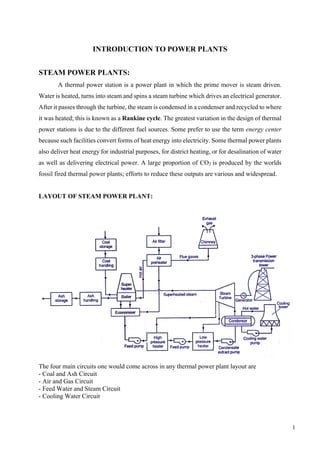
  • 1. 1 INTRODUCTION TO POWER PLANTS STEAM POWER PLANTS: A thermal power station is a power plant in which the prime mover is steam driven. Water is heated, turns into steam and spins a steam turbine which drives an electrical generator. After it passes through the turbine, the steam is condensed in a condenser and recycled to where it was heated; this is known as a Rankine cycle. The greatest variation in the design of thermal power stations is due to the different fuel sources. Some prefer to use the term energy center because such facilities convert forms of heat energy into electricity. Some thermal power plants also deliver heat energy for industrial purposes, for district heating, or for desalination of water as well as delivering electrical power. A large proportion of CO2 is produced by the worlds fossil fired thermal power plants; efforts to reduce these outputs are various and widespread. LAYOUT OF STEAM POWER PLANT: The four main circuits one would come across in any thermal power plant layout are - Coal and Ash Circuit - Air and Gas Circuit - Feed Water and Steam Circuit - Cooling Water Circuit
  • 2. 2 Coal and Ash Circuit Coal and Ash circuit in a thermal power plant layout mainly takes care of feeding the boiler with coal from the storage for combustion. The ash that is generated during combustion is collected at the back of the boiler and removed to the ash storage by scrap conveyors. The combustion in the Coal and Ash circuit is controlled by regulating the speed and the quality of coal entering the grate and the damper openings. Air and Gas Circuit Air from the atmosphere is directed into the furnace through the air preheated by the action of a forced draught fan or induced draught fan. The dust from the air is removed before it enters the combustion chamber of the thermal power plant layout. The exhaust gases from the combustion heat the air, which goes through a heat exchanger and is finally let off into the environment. Feed Water and Steam Circuit The steam produced in the boiler is supplied to the turbines to generate power. The steam that is expelled by the prime mover in the thermal power plant layout is then condensed in a condenser for re-use in the boiler. The condensed water is forced through a pump into the feed water heaters where it is heated using the steam from different points in the turbine. To make up for the lost steam and water while passing through the various components of the thermal power plant layout, feed water is supplied through external sources. Feed water is purified in a purifying plant to reduce the dissolve salts that could scale the boiler tubes. Cooling Water Circuit The quantity of cooling water required to cool the steam in a thermal power plant layout is significantly high and hence it is supplied from a natural water source like a lake or a river. After passing through screens that remove particles that can plug the condenser tubes in a thermal power plant layout, it is passed through the condenser where the steam is condensed. The water is finally discharged back into the water source after cooling. Cooling water circuit can also be a closed system where the cooled water is sent through cooling towers for re-use in the power plant. The cooling water circulation in the condenser of a thermal power plant layout helps in maintaining a low pressure in the condenser all throughout. All these circuits are integrated to form a thermal power plant layout that generates electricity to meet our needs.
  • 3. 3 Advantages ➢ Generation of power is continuous. ➢ Initial cost low compared to hydel plant. ➢ Less space required. ➢ This can be located near the load centre so that the transmission losses are reduced. ➢ It can respond to rapidly changing loads. Disadvantages ➢ Long time required for installation. ➢ Transportation and handling of fuels major difficulty. ➢ Efficiency of plant is less. ➢ Power generation cost is high compared to hydel power plant. ➢ Maintenance cost is high. HYDEL POWER PLANTS Hydroelectric power plants convert the hydraulic potential energy from water into electrical energy. Such plants are suitable were water with suitable head are available. The layout covered in this article is just a simple one and only cover the important parts of hydroelectric plant. LAYOUT OF HYDEL POWER PLANT:
  • 4. 4 (1) Dam Dams are structures built over rivers to stop the water flow and form a reservoir. The reservoir stores the water flowing down the river. This water is diverted to turbines in power stations. The dams collect water during the rainy season and stores it, thus allowing for a steady flow through the turbines throughout the year. Dams are also used for controlling floods and irrigation. The dams should be water-tight and should be able to withstand the pressure exerted by the water on it. There are different types of dams such as arch dams, gravity dams and buttress dams. The height of water in the dam is called head race. (2) Spillway A spillway as the name suggests could be called as a way for spilling of water from dams. It is used to provide for the release of flood water from a dam. It is used to prevent over toping of the dams which could result in damage or failure of dams. Spillways could be controlled type or uncontrolled type. The uncontrolled types start releasing water upon water rising above a particular level. But in case of the controlled type, regulation of flow is possible. (3) Penstock and Tunnels Penstocks are pipes which carry water from the reservoir to the turbines inside power station. They are usually made of steel and are equipped with gate systems. Water under high pressure flows through the penstock. A tunnel serves the same purpose as a penstock. It is used when an obstruction is present between the dam and power station such as a mountain. (4) Surge Tank Surge tanks are tanks connected to the water conductor system. It serves the purpose of reducing water hammering in pipes which can cause damage to pipes. The sudden surges of water in penstock is taken by the surge tank, and when the water requirements increase, it supplies the collected water thereby regulating water flow and pressure inside the penstock. (5) Power Station Power station contains a turbine coupled to a generator. The water brought to the power station rotates the vanes of the turbine producing torque and rotation of turbine shaft. This rotational torque is transferred to the generator and is converted into electricity.
  • 5. 5 The used water is released through the tail race. The difference between head race and tail race is called gross head and by subtracting the frictional losses we get the net head available to the turbine for generation of electricity. Advantages ➢ Water the working fluid is natural and available plenty. ➢ Life of the plant is very long. ➢ Running cost and maintenance are very low. ➢ Highly reliable. ➢ Running cost is low. ➢ Maintenance and operation costs are very less. ➢ No fuel transport problem. ➢ No ash disposal problem. Disadvantages ➢ Initial cost of plant is very high. ➢ Power generation depends on quantity of water available which depends on rainfall. ➢ Transmission losses are very high. ➢ More time is required for erection. DIESEL POWER PLANTS Diesel power plants produce power from a diesel engine. Diesel electric plants in the range of 2 to 50 MW capacities are used as central stations for small electric supply networks and used as a standby to hydroelectric or thermal plants where continuous power supply is needed. Diesel power plant is not economical compared to other power plants. The diesel power plants are cheaply used in the fields mentioned below. 1. Mobile electric plants 2. Standby units 3. Emergency power plants 4. Starting stations of existing plants 5. Central power station etc.
  • 6. 6 LAYOUT OF DIESEL POWER PLANT: Figure shows the arrangements of the engine and its auxiliaries in a diesel power plant. The major components of the diesel power plant are: 1) Engine Engine is the heart of a diesel power plant. Engine is directly connected through a gear box to the generator. Generally two-stroke engines are used for power generation. Now a days, advanced super & turbo charged high speed engines are available for power production. 2) Air supply system Air inlet is arranged outside the engine room. Air from the atmosphere is filtered by air filter and conveyed to the inlet manifold of engine. In large plants supercharger/turbocharger is used for increasing the pressure of input air which increases the power output. 3) Exhaust System This includes the silencers and connecting ducts. The heat content of the exhaust gas is utilized in a turbine in a turbocharger to compress the air input to the engine. 4) Fuel System Fuel is stored in a tank from where it flows to the fuel pump through a filter. Fuel is injected to the engine as per the load requirement.
  • 7. 7 5) Cooling system This system includes water circulating pumps, cooling towers, water filter etc. Cooling water is circulated through the engine block to keep the temperature of the engine in the safe range. 6) Lubricating system Lubrication system includes the air pumps, oil tanks, filters, coolers and pipe lines. Lubricant is given to reduce friction of moving parts and reduce the wear and tear of the engine parts. 7) Starting System There are three commonly used starting systems, they are; 1) A petrol driven auxiliary engine 2) Use of electric motors. 3) Use of compressed air from an air compressor at a pressure of 20 Kg/cm. 8) Governing system The function of a governing system is to maintain the speed of the engine constant irrespective of load on the plant. This is done by varying fuel supply to the engine according to load. Advantages ➢ Diesel power plants can be quickly installed and commissioned. ➢ Quick starting. ➢ Requires minimum labour. ➢ Plant is smaller, operate at high efficiency and simple compared to steam power plant. ➢ It can be located near to load centres. Disadvantages ➢ Capacity of plant is low. ➢ Fuel, repair and maintenance cost are high. ➢ Life of plant is low compared to steam power plant. ➢ Lubrication costs are very high. ➢ Not guaranteed for operation under continuous overloads. ➢ Noise is a serious problem in diesel power plant. ➢ Diesel power plant cannot be constructed for large scale.
  • 8. 8 NUCLEAR POWER PLANTS Nuclear power is the use of sustained or controlled nuclear fission to generate heat and do useful work. Nuclear Electric Plants, Nuclear Ships and Submarines use controlled nuclear energy to heat water and produce steam, while in space, nuclear energy decays naturally in a radioisotope thermoelectric generator. Scientists are experimenting with fusion energy for future generation, but these experiments do not currently generate useful energy. Nuclear power provides about 6% of the world's energy and 13–14% of the world's electricity, with the U.S., France, and Japan together accounting for about 50% of nuclear generated electricity. Also, more than 150 naval vessels using nuclear propulsion have been built. Just as many conventional thermal power stations generate electricity by harnessing the thermal energy released from burning fossil fuels, nuclear power plants convert the energy released from the nucleus of an atom, typically via nuclear fission. LAYOUT OF NUCLEAR POWER PLANT:
  • 9. 9 NUCLEAR REACTOR A nuclear reactor is an apparatus in which heat is produced due to nuclear fission chain reaction. Fig. shows the various parts of reactor, which are as follows: 1. Nuclear Fuel 2. Moderator 3. Control Rods 4. Reflector 5. Reactors Vessel 6. Biological Shielding 7. Coolant. Nuclear reactor 1. Nuclear Fuel Fuel of a nuclear reactor should be fissionable material which can be defined as an element or isotope whose nuclei can be caused to undergo nuclear fission by nuclear bombardment and to produce a fission chain reaction. It can be one or all of the following U233 , U235 and Pu239 . Natural uranium found in earth crust contains three isotopes namely U234 , U235 and U238 and their average percentage is as follows: U238 - 99.3% U235 - 0.7% U234 - Trace
  • 10. 10 2. Moderator In the chain reaction the neutrons produced are fast moving neutrons. These fast moving neutrons are far less effective in causing the fission of U235 and try to escape from the reactor. To improve the utilization of these neutrons their speed is reduced. It is done by colliding them with the nuclei of other material which is lighter, does not capture the neutrons but scatters them. Each such collision causes loss of energy, and the speed of the fast moving neutrons is reduced. Such material is called Moderator. The slow neutrons (Thermal Neutrons) so produced are easily captured by the nuclear fuel and the chain reaction proceeds smoothly. Graphite, heavy water and beryllium are generally used as moderator 3. Control Rods The Control and operation of a nuclear reactor is quite different from a fossil fuelled (coal or oil fired) furnace. The energy produced in the reactor due to fission of nuclear fuel during chain reaction is so much that if it is not controlled properly the entire core and surrounding structure may melt and radioactive fission products may come out of the reactor thus making it uninhabitable. This implies that we should have some means to control the power of reactor. This is done by means of control rods. Control rods in the cylindrical or sheet form are made of boron or cadmium. These rods can be moved in and out of the holes in the reactor core assembly. Their insertion absorbs more neutrons and damps down the reaction and their withdrawal absorbs less neutrons. Thus power of reaction is controlled by shifting control rods which may be done manually or automatically. 4. Reflector The neutrons produced during the fission process will be partly absorbed by the fuel rods, moderator, coolant or structural material etc. Neutrons left unabsorbed will try to leave the reactor core never to return to it and will be lost. Such losses should be minimized. It is done by surrounding the reactor core by a material called reflector which will send the neutrons back into the core. The returned neutrons can then cause more fission and improve the neutrons economy of' the reactor. Generally the reflector is made up of graphite and beryllium. 5. Reactor Vessel It is a. strong walled container housing the cure of the power reactor. It contains moderator, reflector, thermal shielding and control rods.
  • 11. 11 6. Biological Shielding Shielding the radioactive zones in the reactor roan possible radiation hazard is essential to protect, the operating men from the harmful effects. During fission of nuclear fuel, alpha particles, beta particles, deadly gamma rays and neutrons are produced. Out of these gamma rays are of main significance. A protection must be provided against them. Thick layers of lead or concrete are provided round the reactor for stopping the gamma rays. Thick layers of metals or plastics are sufficient to stop the alpha and beta particles. 7. Coolant Coolant flows through and around the reactor core. It is used to transfer the large amount of heat produced in the reactor due to fission of the nuclear fuel during chain reaction. The coolant either transfers its heat to another medium or if the coolant used is water it takes up the heat and gets converted into steam in the reactor which is directly sent to the turbine. Advantages ➢ Need less space. ➢ Fuel consumption is small, hence transportation and storage charges are low. ➢ Well suited for large power demands. ➢ Less work men required. Disadvantages ➢ Capital cost very high. ➢ Radioactive wastes, if not disposed properly have adverse effect on environment. ➢ Maintenance cost high. GAS TURBINE POWER PLANTS A gas turbine, also called a combustion turbine, is a type of internal combustion engine. It has an upstream rotating compressor coupled to a downstream turbine, and a combustion chamber in-between. Energy is added to the gas stream in the combustor, where fuel is mixed with air and ignited. In the high pressure environment of the combustor, combustion of the fuel increases the temperature. The products of the combustion are forced into the turbine section. There, the high velocity and volume of the gas flow is directed through a nozzle over the turbine's blades, spinning the turbine which powers the compressor and, for some turbines, drives their mechanical output. The energy given up to the turbine comes from the reduction in the temperature and pressure of the exhaust gas.
  • 12. 12 LAYOUT OF GAS TURBINE POWER PLANT The gas turbine power plants which are used in electric power industry are classified into two groups as per the cycle of operation. (1) Open cycle gas turbine. (2) Closed cycle gas turbine. Open cycle gas turbine 1- Atmospheric Air 2- Compressed Atmospheric Air 3- Fuel air mixture after compression 4- Exhaust gases. The heated gases coming out of combustion chamber are then passed to the turbine where it expands doing mechanical work. Part of the power developed by the turbine is utilized in driving the compressor and other accessories and remaining is used for power generation. Since ambient air enters into the compressor and gases coming out of turbine are exhausted into the atmosphere, the working medium must be replaced continuously. This type of cycle is known as open cycle gas turbine plant and is mainly used in majority of gas turbine power plants as it has many inherent advantages. Advantages 1. Warm-up time is very less. 2. Low weight and size. 3. Almost any hydrocarbon fuels can be used. 4. Open cycle plants occupy comparatively little space. 6. Very economical when compared to other plants. 7. Independent of separate cooling medium.
  • 13. 13 Disadvantages 1. The part load efficiency of the open cycle plant decreases rapidly as the considerable percentage of power developed by the turbine is used to drive the compressor. 2. The system is sensitive to the component efficiency; particularly that of compressor. 3. The open cycle plant is sensitive to changes in the atmospheric air temperature, pressure and humidity. 3. The open-cycle gas turbine plant has high air rate compared to the other cycles. 4. It is essential that the dust should be prevented from entering into the compressor. 5. The deposition of the carbon and ash on the turbine blades is not at all desirable as it also reduces the efficiency of the turbine. Closed cycle gas turbine 1- Low Pressure Working Fluid @ Low temperature 2- High Pressure Working Fluid 3- Fuel + Working Fluid mixture @ High Pressure and Temperature 4- Low Pressure Working Fluid @ Temperature T4 < Temperature T3 In closed cycle gas turbine plant, the working fluid (air or any other suitable gas) coming out from compressor is heated in a heater by an external source at constant pressure. The high temperature and high-pressure air coming out from the external heater is passed through the gas turbine. The fluid coming out from the turbine is cooled to its original temperature in the cooler using external cooling source before passing to the compressor.
  • 14. 14 The working fluid is continuously used in the system without its change of phase and the required heat is given to the working fluid in the heat exchanger. Advantages 1. The closed cycle plant is not sensitive to changes in the atmospheric air temperature, pressure and humidity. 2. The closed cycle avoids erosion of the turbine blades due to the contaminated gases and fouling of compressor blades due to dust. 3. The need for filtration of the incoming air which is a severe problem in open cycle plant is completely eliminated. 4. Load variation is usually obtained by varying the absolute pressure and mass flow of the circulating medium, while the pressure ratio, the temperatures and the air velocities remain almost constant. 5. The density of the working medium can be maintained high by increasing internal pressure range, therefore, the compressor and turbine are smaller for their rated output. The high density of the working fluid further increases the heat transfer properties in the heat exchanger. 6. As indirect heating is used in closed cycle plant, the inferior oil or solid fuel can be used in the furnace and these fuels can be used more economically because these are available in abundance. 8. The maintenance cost is low and reliability is high due to longer useful life. Disadvantages 1. The system is dependent on external means as considerable quantity of cooling water is required in the pre-cooler. 2. Higher internal pressures involve complicated design of all components and high quality material is required which increases the cost of the plant. 3. The response to the load variations is poor compared to the open-cycle plant. 4. It requires very big heat-exchangers as the heating of workings fluid is done indirectly.
  • 15. 15 MAGNETO HYDRO DYNAMIC (MHD) POWER PLANTS MHD power generation is a new system of electric power generation which is said to be of high efficiency and low pollution. In advanced countries MHD generator are widely used but in developing countries like India it is still under construction. This construction work is in progress at Tiruchirapalli in Tamilnadu under joint efforts of BARC (Bhabha Atomic Research Centre), BHEL, Associated Cement Corporation and Russian technologists. As its name implies, magneto-hydro-dynamic (MHD) is concerned with the flow of conducting fluid in presence of magnetic and electric field. This fluid may be gas at elevated temperature or liquid metal like sodium or potassium. A MHD generator is a device for converting heat energy of fuel directly into electric energy without a conventional electric generator. The basic difference between conventional generator and MHD generator is in the nature of conductor. Principle of MHD Power Generation When an electric conductor moves across a magnetic field; an emf is induced in it, which produced an electric current. This is the principle of the conventional generator also, where the conductors consists of copper strips. In MHD generator the solid conductors are replaced by a gaseous conductor; i.e.an ionized gas. If such gas is passed at high velocity through a powerful magnetic field, a current is generated and can extract by placing electrodes in a suitable position in the stream.
  • 16. 16 LAYOUT OF MHD POWER PLANT A MHD conversion is known as direct energy conversion because it produces electricity directly from heat source without the necessity of the additional stage of steam generation as in a steam power plant. An ionized gas is employed as a conducting field. Ionization is produced either by thermal means i.e. by an elevated temperature or by seeding with substance like cesium or potassium vapour which ionize at relatively low temperature. The atom of seed element split off electrons. The presence of negatively charge electrons make the carrier gas an electrical conductor. Advantages 1. Large amount of power is generated. 2. No moving parts, so more reliable. 3. Closed cycle system produces power, free of pollution. 4. Ability to reach its full power as soon as started. 5. Size of the plant is considerably small. 6. Low overall operation cost. 7. Better utilization of fuel. Disadvantages 1. Needs very large magnets (high expensive). 2. Very high friction and heat transfer losses. 3. It suffers from the reverse flow of electrons through the conducting fluids around the ends of the magnetic field.
  • 17. 17 COMBINED POWER CYCLES In electric power generation a combined cycle is an assembly of heat engines that work in tandem off the same source of heat, converting it into mechanical energy, which in turn usually drives electrical generators. The principle is that the exhaust of one heat engine is used as the heat source for another, thus extracting more useful energy from the heat, increasing the system's overall efficiency. This works because heat engines are only able to use a portion of the energy their fuel generates (usually less than 50%). The objective of this approach is to use all of the heat energy in a power system at the different temperature levels at which it becomes available to produce work, or steam, or the heating of air or water, thereby rejecting a minimum of energy waste. The best approach is the use of combined cycles. There may be various combinations of the combined cycles depending upon the place or country requirements. Even nuclear power plant may be used in the combined cycles. GT-ST Combined Power plants It has been found that a considerable amount of heat energy goes as a waste with the exhaust of the gas turbine. This energy must be utilized. The complete use of the energy available to a system is called the total energy approach. The remaining heat (e.g., hot exhaust fumes) from combustion is generally wasted. Combining two or more thermodynamic cycle’s results in improved overall efficiency, reducing fuel costs. In stationary power plants, a successful, common combination is the Brayton cycle (in the form of a turbine burning natural gas or synthesis gas from coal) and the Rankine cycle (in the form of a steam power plant). Multiple stage turbine or steam cylinders are also common.
  • 19. 19 LOAD DURATION CURVE The load demand on a power system is governed by the consumers and for a system supplying industrial and domestic consumers, it varies within wide limits. This variation of load can be considered as daily, weekly, monthly or yearly. Such load curves are termed as “Chronological load Curves”. If the ordinates of the chronological load curves are arranged in the descending order of magnitude with the highest ordinates on left, a new type of load curve known as “load duration curve” is obtained. If any point is taken on this curve then the abscissa of this point will show the number of hours per year during which the load exceeds the value denoted by its ordinate. The lower part of the curve consisting of the loads which are to be supplied for almost the whole number of hours in a year, represents the “Base Load”, while the upperpart, comprising loads which are required for relatively few hours per year, represents the “Peak Load”.