Automatic Voltage Range (AVR) - Sollatek
•
1 like•1,384 views

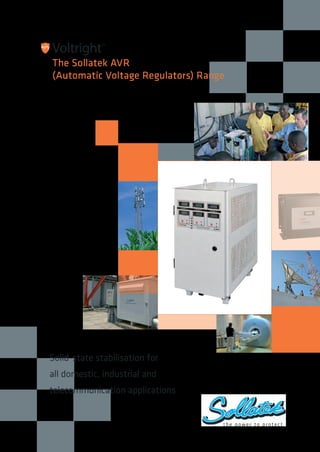
Solid-state stabilisation for all domestic, industrial and telecommunication applications.

Recommended
More Related Content
What's hot
What's hot (20)
Viewers also liked
Viewers also liked (18)
Similar to Automatic Voltage Range (AVR) - Sollatek
Similar to Automatic Voltage Range (AVR) - Sollatek (20)
Recently uploaded
Recently uploaded (20)
Automatic Voltage Range (AVR) - Sollatek
- 1. Solid-state stabilisation for all domestic, industrial and telecommunication applications t h e p o w e r to p ro te c t ™ Voltright The Sollatek AVR (Automatic Voltage Regulators) Range ™ AVR BROCHURE V.4.0.indd 1 17/02/2014 10:26
- 2. • Microprocessor controlled - high speed response. • Solid State reliability - no moving parts. • Widest input variation (of -30% to +22% as standard). • 1250 Volts per second correction speed. • High output correction accuracy (of +/-4%) exceeds EC standards. • Faster and smaller than servo operated units. • Less expensive to buy and run than servo operated units. • Quiet, unobtrusive operation. • Wide input frequency tolerance between 45 to 75 Hz allowing unit to function properly in areas of severe frequency disturbances. • High overload capability of up to 150% for 4 minutes. • Very low losses and minimal heat dissipation due to an efficiency of over 96% at full load. • Warranty of 2 years. Sollatek provides full back up support on all its products, with local support in over twenty countries worldwide. Main features and benefits Voltright The Sollatek AVR Range Automatic Voltage Regulators ™ Contents Single phase small Page 4-5 Single phase large Page 6-7 Three phase indoor Page 8-9 Three phase outdoor Isolating transformer Page 10-11 Options Page 12 Operation principle Page 13 Technical notes Page 14 Input and output voltage Page 15 Wherever mains supply is erratic and unreliable, Sollatek - a world leader in the field of voltage regulation and protection, has the ideal solution to protect all your domestic, commercial and industrial installations. From small domestic (250 watt) to large industrial 500kVA applications, single and three phase applications, the Sollatek range of voltage regulators is your solution in the most erratic of power conditions. The Sollatek AVR is a state of the art solid state stabiliser. Using microprocessor technology, the AVR will rapidly detect voltage variations and correct the output to ensure 220V (+/-4%) supply. The Sollatek AVR has a very wide input range (-30% to +22%) and a voltage correction speed of 1250 Volts per second. No mechanical parts means that the AVR doesn’t require maintenance and will not be affected by dusty environments as other mechanical (for example Servo type) stabilisers. 2 AVR BROCHURE V.4.0.indd 2 17/02/2014 10:26
- 3. General Specifications Input Frequency range 45Hz to 75Hz (i.e 50Hz –10%, +50%. or 60Hz –25%, +25%). Additional voltage THD* <0.2% at input (tested at 100% linear load), (No PWM methods used). Maximum input THD* Can withstand up to 10% THD from the supply. Output Additional voltage THD* <0.25% at output (tested at 100% linear load), (No PWM methods used). Crest factor > 1: 3 permissible on load current (tested at 100% load). Synchronization Output synchronized to input. Permissible overload 1000% for 100ms, 150% for 4 minutes, 110% for 10 minutes. Load types Designed to run lighting, motors, battery chargers, communications equipment, office equipment, SMPS, air- conditioners, compressors, industrial machines, medical equipment and others. Suitable for all domestic, commercial and industrial sites. General Technology All solid state (static) switching. Efficiency <96% (at 100% linear load). Control Microcontroller based control system provides self checks, system integrity monitoring and diagnostic indicators. Control protection Internal surge arrestors and filters in control circuit protect against disturbances. Filtering algorithms and fault tolerant software protect against disturbances and false measurements. Ambienttemperaturerange 0 to +55ºC. Relative humidity < 95%, non condensing. Acoustic noise < 45 dB (A). Expected service life > 25 years. Standards Manufactured to comply with :- ISO9001:2000, CE, EN 50081-1:1992, EN 50082-1:1998, EN 55022:1998, EN 61000-4-2:1995/1998, EN 61000-4-3:1996, EN 61000-4-4:1995, EN 61000-4-5:1995, EN 61000-4-6:1996, EN 61000-4-11:1994, DD ENV 50204, BS EN 61558-1, EN 60065, EN 60555. Input range -30% to +22% Output accuracy ± 4% Correction speed 1250 Volts per sec. Response within 15 millisecond . kVA rating The Sollatek AVR range is wide and covers units from as small as 250W up to 100kVA in single phase and 10kVA to 2mVA in three phase. To choose the correct size from the Sollatek range, refer to the kVA calculator at the back. Efficiency 88% at 25% load 94% at 50% load 96% at 75% load 97% at 100% load Power factors Unaffected by load power factor. * Total harmonic distortion Comparison Chart Sollatek Sollatek Other relay based Servo/mechanical Benefits of Sollatek AVR AVR range SVS range Stabilisers Stabilisers Microprocessor Reliable. controlled Yes Yes No/some No Accurate operation allows advanced functions. Relays No Yes (uses Yes No Faster correction than mechanical types. zero voltage Quiet. switching) Low in cost. Mechanical elements No No No Yes - uses motorised variable No mechanical elements means transformer to adjust output no servicing or maintenance required. Extremely fast voltage correction speed. Requires servicing Yes - especially in /maintenance No No No dusty environment Low admin cost. Typical voltage The wide range is ideal, and in some cases essential input range -30% to +22% -26% to +19% ±15% ±12.5% in countries with chronic mains supply problems. Typical voltage output range ± 4% ± 6% ± 6% ±1% ± 4% exceeds most international standards. Cost comparison (rated 1 to 4)* 3 2 4 4 (most expensive if Value for money. same input range compared ie ± 25%) * 4 = most expensive 3 AVR BROCHURE V.4.0.indd 3 17/02/2014 10:26
- 4. Single Phase small AVR - 250VA to 2500VA Main Features and Specifications Introduction Suitable for all applications for domestic and small office use, this range of AVRs is built into an attractive and modern enclosure to suit and blend with modern equipment. Sollatek AVRs from 250VA up to 1600VA are built into a plastic enclosure (see table opposite for dimensions). The larger units are built into a metal enclosure with a plastic facia, again providing a smart unit that will blend well with other equipment. Features LED display - A seventeen Light Emitting Diodes (LED) display is built on the front panel. This display provides the following indications: Input Voltage - 7 LEDs indicate the state of the incoming voltage. At a glance it is possible to see the level of under-voltage or over-voltage. Output Voltage - 5 LEDs indicate the state of the output voltage. A zero % indication shows the output voltage reaching your equipment is at the correct nominal voltage. Load Current -5 LEDs display the percentage of rated current the load is drawing through the AVR. Although the Sollatek AVR will withstand 110% overload for long durations, it is never recommended to overload any equipment. The overload indication makes it possible to reduce the load, allowing the AVR to work safely. If the overload persists then the Sollatek AVR will disconnect the load for protection. Includes overload protection E n g l a n d INPUT VOLTAGE +15% +5% 0% -5% -10% -20% -25% OUTPUT VOLTAGE +5% +5% 0% -10% -20% LOAD CURRENT over load 100% 75% 50% 0% avr INPUTVOLTAGE OUTPUT VOLTAGE load current 500watts microprocessor controlled REGULATOR E n g l a n d 500VA +10% +5% 0% -10% -20% Overload 100% 75% 50% 0% +15% +5% +0% -5% -10% -20% -25% avr AUTOMATIC VOLTAGE REGULATOR Front panel for Case type A LED display showing corrected output voltage LED display showing load current LED display showing input voltage state Front panel Case type B, C and D LED display showing load level LED display showing corrected output voltage LED display showing input voltage state 4 AVR BROCHURE V.4.0.indd 4 17/02/2014 10:26
- 5. Single Phase small Rear panels socket availability Rear panel Case type A and B All the above sockets types can be ordered on the rear panels Outlet (See socket availability below) On/off switch Cable entry Fuse Rear panel Case type C and D On/off switch FuseCable entry Outlet (See socket availability below) Model Amps Voltage VA Socket Weight Dims Case material AVR01-22 1 230 230 UK,FR,SCH,UK5 4 124 x 193 x 100 Plastic (ABS) AVR02-22 2 230 460 UK,FR,SCH,UK5 5 124 x 193 x 100 Plastic (ABS) AVR05-22 5 230 1150 UK,FR,SCH,UK15 12 145 x 285 x 212 Metal AVR10-22 10 230 2300 UK,FR,SCH,UK15 15 179 x 335 x 212 Metal AVR02-11 2 110 220 US 3 124 x 193 x 100 Plastic (ABS) AVR04-11 4 110 440 US 4 124 x 193 x 100 Plastic (ABS) AVR05-11 5 110 550 US 5 124 x 193 x 100 Plastic (ABS) AVR10-11 10 110 1100 US 11 161 x 277 x 133 Plastic (ABS) AVR20-11 20 110 2200 US 14 215 x 347 x 520 Metal specifications US UK 13amp UK 15amp UK 5 amp FRENCH (FR) SCHUKO (SCH) 5 AVR BROCHURE V.4.0.indd 5 17/02/2014 10:26
- 6. Single Phase large AVR - 5kVA to 100kVA Main Features and Specifications Introduction Suitable for large applications covering a small office to an entire apartment or house, or even a small workshop. Available from 5kVA (21 Amps at 230V supply) up to 100kVA (260 Amps at 230V) and built into a tower metal enclosure with a small footprint of 295x210 mm (For models up to 10kVA 230V). Included as standard, this range of AVRs includes an LCD (liquid crystal display) which provides input voltage, output voltage and output current monitoring. Using state of the art technology the Sollatek AVR displays load current in real time, input voltage and output voltage. (Display toggles between input and output voltage, using a switch). For AVR models up to 10kVA @ 230V (AVR40-22) Front panel AVR5k, AVR7.5k, AVR 10k Two LEDs showing the selected voltage display mode Switch to select the voltage display between input voltage or output voltage Display showing output voltage or input voltage in real time Display showing load current in real time 6 AVR BROCHURE V.4.0.indd 6 17/02/2014 10:26
- 7. Single Phase large Model Amps Voltage kVA Weight Dims AVR20-22 20 230 4.6 40 215 x 347 x 520 AVR30-22 30 230 6.9 55 215 x 347 x 520 AVR40-22 40 230 9.2 60 215 x 347 x 520 AVR50-22 50 230 11.5 82 460 x 785 x 445 AVR75-22 75 230 17.2 100 460 x 785 x 445 AVR100-22 100 230 23.0 114 460 x 785 x 445 AVR250-22 250 230 57.5 350 680 x 1200 x 1130 AVR300-22 300 230 69.0 382 680 x 1200 x 1130 AVR350-22 350 230 80.5 397 680 x 1200 x 1130 AVR400-22 400 230 92.0 423 680 x 1200 x 1130 AVR30-11 30 110 3.3 36 215 x 347 x 520 AVR40-11 40 110 4.4 40 215 x 347 x 520 AVR50-11 50 110 5.5 50 460 x 785 x 445 AVR75-11 75 110 8.2 56 460 x 785 x 445 AVR100-11 100 110 11.0 65 460 x 785 x 445 AVR250-11 250 110 27.5 127 680 x 1200 x 1130 AVR300-11 300 110 33.0 186 680 x 1200 x 1130 AVR350-11 350 110 38.5 204 680 x 1200 x 1130 AVR400-11 400 110 44.0 287 680 x 1200 x 1130 AVR100-22 with digital display AVR300-22 specifications 7 AVR BROCHURE V.4.0.indd 7 17/02/2014 10:26
- 8. Three Phase Indoor AVR Three Phase Main Features and Specifications Introduction The three phase AVR is made up from three identical single phase regulator units. Each of these monitors its own output voltage and adjusts for variations in mains supply voltage so as to maintain an output voltage within close limits. The Sollatek three phase AVRs all feature the same input voltage range as standard of -30% to +22%, making them ideal for all applications where the voltage supply is erratic. Also, when compared to stabilisers of the same input range, the Sollatek AVR is one of the most competitively priced units available. The Sollatek three phase AVR range is easy to order. All units are rated by the number of AMPS per phase and the input/output voltage. For example: AVR3x20-22-ABCDEFIMNOPRSTWY Options A AVS B Input circuit breaker C Output circuit breaker D Class II surge and spike protection E Enhanced Input Voltage 90V F Phase selector I Isolating transformer M Digital meters N Auto bypass with override O Outdoor enclosure (IP44) P Changeover switch R RFI S Class I & II lightning, surge and spike protection T Line reactor W Wide input voltage Y Manual bypass switch Number of phases Output current per phase Input =230Vac Output =230Vac 8 AVR BROCHURE V.4.0.indd 8 17/02/2014 10:26
- 9. Three Phase Indoor VOLTAGE OUTPUT CURRENT VOLTAGE OUTPUT CURRENT VOLTAGE OUTPUT CURRENT INPUT OUTPUT INPUT OUTPUT INPUT OUTPUT VOLTAGE SELECT VOLTAGE SELECT VOLTAGE SELECT Voltright™ Three Phase Automatic Voltage Regulator Microprocessor Controlled Solid State AVR Pantone 165 Black (cutter) 74930198 3Phase AVR-AM Label OUTPUT NOTES Front panel To calculate the VA: VA = Single phase amps x single phase voltage x 3 i.e: 20 (amps) x 230 (voltage) x 3 = 13800VA To convert to kVA: Divide the VA by 1000: i.e: 13800 ÷ 1000 = 13.8kVA All the above are standard models. Input range for the standard models is -30% to +22%. Other models can be made to order. To reduce cost and in areas of more stable input voltage, Sollatek can provide the M (AVRM) series with an input of +/-15%. The model number will be as above but with an M suffix. E.g. AVRM3x20-22. For costs, dimensions and weights please apply to Sollatek. Function diagram of AVR 3xN D W H Model Amps per phase Voltage KVA Weight Dims (mm) kg W x D x H AVR3x20-22 20 230/400 13.8 100 450 x 635 x 850 AVR3x30-22 30 230/400 20.7 150 450 x 635 x 850 AVR3x50-22 50 230/400 34.5 210 500 x 685 x 1060 AVR3x75-22 75 230/400 51.7 285 600 x 735 x 1110 AVR3x100-22 100 230/400 69.0 400 500 x 835 x 1280 AVR3x150-22 150 230/400 103.5 450 500 x 835 x 1280 AVR3x250-22 250 230/400 172.5 675 680 x 1200 x 2070 AVR3x300-22 300 230/400 207.0 735 680 x 1200 x 2070 AVR3x400-22 400 230/400 276.0 790 680 x 1200 x 2070 AVR3x700-22 700 230/400 483.0 1200 1360 x 1200 x 2070 AVR3x800-22 800 230/400 552 1590 1360 x 1200x 2070 AVR3x900-22 900 230/400 621 1700 1360 x1200 x 2070 AVR3x1000-22 1000 230/400 690 1850 2040 x1200 x 2070 Up to 3000A per phase available specifications Block diagram of Sollatek Three Phase AVR 9 AVR BROCHURE V.4.0.indd 9 17/02/2014 10:26
- 10. Three Phase AVR Three Phase Including Isolating Transformer Main Features and Specifications Introduction The Sollatek isolating AVR is a version of the standard Sollatek AVR. Designed specifically to provide the high level of protection required for telecommunication applications and for equipment that requires a higher level of surge, spike, & noise protection. Using an isolating transformer, the AVR provides a clean neutral and 10:1 attenuation ratio ensuring that noise on the output is significantly reduced relative to the input. As the Sollatek isolating AVR requires no incoming neutral it is protected against ‘loss of neutral’ problems. These can occur when the neutral connection is lost, either by damage or through the neutral cable being stolen and can result in voltage imbalance and damage in non-isolating regulators. These models as standard include various additional features that are normally provided as optional extras. These include a higher IP rating of 44 to allow outdoor installation. The standard inclusion of output circuit breaker, manual by pass and automatic voltage switcher function all make this unit the preferred choice for mission critical applications. Features • Designed for telecom applications • Designed for remote operation where a high degree of reliability is essential • Input delta/star isolating transformer • Weather-proof enclosure • Fully electronic with no moving parts for: - High reliability - Speed of operation - Immunity to dust and other environmental conditions Internal view of an Outdoor Isolating AVR 10 AVR BROCHURE V.4.0.indd 10 17/02/2014 10:26
- 11. specifications Three Phase Model Amps per phase Voltage KVA Weight kg Dimensions (DxWxH) mm Isolating AVR - INDOOR (-I) AVR3x12-22-I 12 230/400 8.3 175 700 x 930 x 1100 AVR3x20-22-I 20 230/400 13.8 250 700 x 930 x 1450 AVR3x30-22-I 30 230/400 20.7 350 700 x 930 x 1450 AVR3x50-22-I 50 230/400 34.5 400 700 x 930 x 1450 AVR3x75-22-I 75 230/400 51.7 500 700 x 930 x 1450 AVR3x100-22-I 100 230/400 69.0 650 900 x 1200 x 1750 AVR3x150-22-I 150 230/400 103.5 1000 900 x 1200 x 1750 Isolating AVR - OUTDOOR (-IO) AVR3x12-22-IO 12 230/400 8.3 150 1110 x 370 x 1090 AVR3x20-22-IO 20 230/400 13.8 230 1110 x 450 x 1190 AVR3x30-22-IO 30 230/400 20.7 325 1110 x 450 x 1190 AVR3x50-22-IO 50 230/400 34.5 375 1110 x 450 x 1190 AVR3x75-22-IO 75 230/400 51.7 475 1310 x 650 x 1290 AVR3x100-22-IO 100 230/400 69.0 620 1310 x 650 x 1290 AVR3x150-22-IO 150 230/400 103.5 950 1310 x 650 x 1290 Larger sizes available upon request Applications • Satellite operators • Infrastructure telecom companies • Embassies worldwide for reliable electrification of their posts • Medical systems for digital imaging, scanning and x-ray equipment • Mobile phone operators • Grid utility companies for voltage regulation to their sub-stations • Various United Nations divisions including WHO, UNICEF and WFP Equipped with • Bypass switch transferring the load to the utility grid • Low and high voltage protection • Surge and lightning protection • Output circuit breaker Standard features include • Wide input frequency tolerance between 45 to 75 Hz allowing unit to function correctly in areas of severe voltage disturbances • High overload capability with up to 150% for 4 minutes • Very low losses and minimal heat dissipation due to high efficiency design • Easy access cabinet with lockable doors 11 AVR BROCHURE V.4.0.indd 11 17/02/2014 10:26
- 12. Three Phase AVR Three Phase OPTIONS Main Features A number of options are available on the Sollatek 3 Phase AVR range; Option A) Automatic Voltage Switcher option (AVS™) The AVS (a Sollatek UK Patent 2139436) option completes the protection that can be offered by the Sollatek AVR. The AVS simply disconnects the mains when the voltage is 'BAD' and re-connects it automatically when the voltage returns to 'GOOD'. Using this principle, the AVS monitors the output of the AVR. If the AVR cannot correct the voltage sufficiently (in cases where the fluctuation is extremely high or extremely low), then the AVS will disconnect the output and thus provide this added protection to the appliance.When the AVR's output is acceptable, the AVS will monitor the supply for 1 minute to ensure stability and will then reconnect the mains. The Sollatek AVS has an additional useful feature of Timesavetm . Using its own microprocessor, the AVS will monitor the time. If the unit has been disconnected for more than 1 minute then the AVS will reconnect within 10 seconds. Option B&C) Input/output circuit breakers Circuit breakers protect the load and the AVR from the harmful effects of overcurrent. It is recommended that all Sollatek AVRs are installed with at least input circuit breakers and, wherever possible, output circuit breakers. These can be provided by the customer or alternatively, for ease of installation and for compactness, they can be ordered as an option to be built in to the AVR. Option D&S) Additional surge/spike suppression - The DSP option: Class I and II. Extra surge/spike suppression is available on the Sollatek 3 Phase AVR range with the DSP. This will provide a high level of protection from lightning induced voltage and other voltage surges on the mains supply. For more information please refer to Sollatek Voltsafe Suppressor brochure. Option E) Enhanced input voltage range Boosts incoming voltage from 90V to 220V instead of the standard. Option F) Phase selector The three phase voltages are constantly monitored by the phase selector and the two best phases are selected to supply the Automatic Voltage Regulator (AVR). In the case of a lost phase the two remaining phases will be used, allowing the site to continue to function as normal. This ensures that the site mains supply is able to be used to the maximum, thereby minimising generator use. Option I) Isolation transformer See page 10 Option M) Digital input/output voltage and current meters The Sollatek 3 Phase AVR can be ordered with meters to indicate the state of the input voltage to compare it with the output voltage. Current meters are useful to ensure that the load does not exceed the rating of the AVR. Option O) Outdoor enclosure See page 10 Option P) Changeover switch Manual switch that will by pass the incoming mains from the AVR directly to the load. The AVR will remain powered on. To take the AVR off-line for maintenance, the system will need to be powered down first. Option R) RFI filter RFI interference can cause malfunctioning of equipment, loss of data and, in some cases, component failure. It can come from the supply side or from the load. If you think your site is potentially prone to RFI problems, please specify this option at the time of ordering. Sollatek engineers will advise regarding the correct RFI filter option. Option T) Line reactor If harmonic interference is known to be present at your site, the line reactor option, connected at the input to the AVR, can be ordered to effectively filter out the unwanted harmonic content. For further details on harmonic pollution, please refer to the technical notes section on the inside back page. Option W) Wide input voltage range Boosts incoming voltage from 120V to 220V instead of the standard. W) Wide input voltage range, boosts incoming voltage from 120V to 220V instead of the standard. Option Y) Manual by-pass switch The function of the bypass switch option is to allow the user to remove a regulator from service whilst the load remains connected to mains power. This has the benefit of allowing safe access to the AVR for servicing without having to disconnect power from the load, thereby reducing system downtime. 12 AVR BROCHURE V.4.0.indd 12 17/02/2014 10:26
- 13. AVR OPERATION PRINCIPLE Main Features AVR Function This is based on an auto transformer with tap changing on the output. There are seven taps to each transformer giving an accurate output voltage for a wide range of input voltage. The taps are switched by generously rated Triac banks to cope with motor start loads. This technique results in a voltage stabiliser which has no moving parts, responds quickly to voltage fluctuations and is not as large or heavy as other AVRs utilising different regulation techniques. A micro-controller forms the heart of the control system. It measures the AVR output voltage and turns on the appropriate Triac bank to select the correct tap. A potentiometer is provided for fine adjustment of the output voltage. The micro-controller also measures the frequency of the mains supply and compensates accordingly. This also means that the AVR will work automatically over a frequency range of 45 - 75Hz and down to as low as 30Hz for short periods to help cope with diesel generator loading problems. Frequency and voltage measurements are filtered by the circuit and software to remove noise and so prevent spurious tap changes. In an industrial environment there can be a large amount of electrical noise and interference present on the mains and load cabling. This may be caused by other equipment in the building such as electric motors and speed controllers, contactors and relays, electric welding, etc. This will distort the waveform of the electricity. To avoid this, spike suppressors are fitted to the AVR input and output to clip any high voltage transients on the line. Additionally, a capacitor type filter is fitted to the measurement input to the AVR to further attenuate spikes and to filter out high frequency noise and interference. As a further precaution, the software programme in the micro performs mathematical filtering using various averaging techniques. The software does a number of checks to ensure that the measurements it is getting are reasonable and consistent. All of these aspects of the design result in an AVR which is rugged and will perform well in an industrial environment. Zero-Voltage Switching The AVR uses an auto transformer with tap changing to regulate the supply. The taps are selected using triacs which are controlled by a microcontroller. The micro measures the voltage of the mains wave- form many times every cycle so as to determine the voltage and decide which tap to select. The micro also uses these measurements to synchronise the running of its software program to the mains wave-form. When a tap change is necessary, the micro watches for the mains voltage to reach zero volts and then it turns off the present Triac and turns on the new Triac. The micro and the triacs are semiconductor devices and switch very fast so that there is no interruption in the supply. This means that the new Triac is now in operation, selecting the new tap, at the very start of the next half cycle of the mains wave-form. The AVR will continue with this tap selected until the measurements by the micro determine that another tap change is necessary. Zero-Voltage Solid State Switching is also superior to Relay/ Mechanical based switching as it avoids interruption to the supply and also superior to servo based switching which apart from slow response and requiring maintenance, produces noise as the motor brushes move during correction. Spike Protection The Sollatek AVR is protected against spike and surges primarily by large Metal Oxide Varistors fitted at the input to the unit (260 Joules - 350VAC). These are fitted between the three lines and neutral and between the three lines and earth. These have the combined function of protecting the AVR and the load. There is also a further Metal Oxide Varistor (1.5Joule - 31VDC) on each circuit board to protect the AVR’s low-voltage circuitry. Polyester capacitors are fitted to all power supplies within the unit to filter out interference. 13 AVR BROCHURE V.4.0.indd 13 17/02/2014 10:26
- 14. AVR TECHNICAL NOTES Main Features In most applications, purchasing a stabiliser is simply a process of deciding the power requirement and the voltage and choosing a suitably rated unit. However, ambient temperature, altitude, load duty cycle, type of load are also all important factors in deciding which AVR to buy. Furthermore, in certain situations it can be necessary to consider in greater detail the characteristics of the electricity supply and connected load when selecting an AVR. Please see the notes below for further details: Ambient Temperature. Ambient temperatures in excess of 40°C should be mentioned at the time of ordering as AVR size or rating may be affected. As a rule of thumb, output power should be de-rated by 10% - 15% per 10°C above 40°C ambient. Supply Frequency. The Sollatek standard ranges of AVRs are suitable for both 50Hz and 60Hz supplies. However, frequencies below 50Hz result in larger transformer and therefore AVR size, while frequencies above 50Hz may enable AVR size to be reduced. Any frequency other than 50Hz should be notified at the order/enquiry stage. Duty Cycle. If the AVR is to be used continually for considerably less than 100% of the time, allowance can be made for this, leading to a reduction in transformer size. The effective power in VA may be estimated from the following formula: Time on = time in minutes that AVR supplies current (say 15 minutes) Total time = total length in minutes of period in question (say 60 minutes) I = Output current (say 20A) In the above example, the AVR supplies 20 Amps for 15 minutes out of every 60 minutes. Duty cycle information may result in cost reduction and should be notified at the time of enquiry/order. Operation at Altitude. The operation of electrical equipment at high altitude causes cooling by the circulation of air to be reduced. The greater the altitude the greater this effect. It is therefore important to indicate that the AVR is destined for a high altitude environment at the time of ordering. In this case, a high altitude is regarded as above 1500m. Motor Starting. Motor loads draw a very high initial starting current from the AVR. Whilst the AVR is designed to be able to supply this initial high current without damage, repeated motor starts within a short period may cause excessive heating in the AVR. If motor based, air conditioner or refrigeration equipment are likely to constitute a large proportion of the AVR load, this should be indicated at the point of enquiry. Since this could result in an increase in AVR size, it may be beneficial in some instances to fit a soft start device to the motor to reduce starting surges. Please contact customer support at Sollatek UK or your nearest Sollatek agent for further advice. Neutral. The Sollatek 3 phase AVRs MUST have a fully rated neutral connection to the supply. Harmonics. It is important to state whether harmonics will be present on the supply, or will be generated by the load. Harmonics can be created by devices such as thyristors, silicon controlled rectifiers, switch mode power supplies, computer, UPS, television loads, fluorescent lamps with electronic ballasts, variable speed drives and welding equipment. Alternatively harmonics can be generated from the supply side by neighboring installations. If you think harmonics are present on the supply please contact customer support at Sollatek UK or your nearest Sollatek agent for further advice. Circuit Breakers. As a minimum, the mains input to the AVR should be protected by a circuit breaker. For full protection an output circuit breaker should also be fitted. The input circuit breaker should be rated at 1.4 x output current. The output breaker should be rated at output current. The Sollatek AVR – single phase models – are all protected by either a fuse or circuit breaker. Circuit Breaker is an option on the three phase models. Spike Protection. The AVR is protected against high voltage surges and spikes on input and output by metal oxide varistor based surge suppressors. Spikes can be caused by lightning, switching heavy reactive equipment such as industrial motors and transformers, arc welding and electrical grid switching. In areas of extremely high spike activity, additional protection may be necessary. Please contact customer support at Sollatek UK or your nearest Sollatek agent for further advice. Cable selection. When selecting cable for the AVR input / out connections, one should bear in mind the input current may be up to 40% higher than the output current of the unit. The input neutral (4-Wire system) must be fitted and be fully rated. Voltage-drop should be kept as low as practicable. Marine Shore Power. Sollatek Isolating AVR (voltage stabilisation and corrosion prevention). Non isolated shore power supplies will quickly corrode marine vessels sacrificial anodes. Without these anodes severe damage will be caused to the vessels immersed metallic parts. An isolating transformer type shore supply must be used to prevent this galvanic corrosion. The shore supply is connected to the AVR transformer’s primary winding, the AVR’s secondary will be connected to the ship side mains input connector. To prevent galvanic corrosion, the AVR’s primary and secondary earth connections are intentionally seperated and for personnel safety the secondary neutral and earth must be connected together with an earth fault detector (GCFI or RCD sold seperately). The AVR electrical equipment is contained in an IP44 lockable enclosure (rain proof) but depending on proximity to the water, additional housing may be required. Please contact Sollatek technical support for further details. Effective VA = Time on (mins) Total Time (mins) (I2 ) x Volts x 3 √ 14 AVR BROCHURE V.4.0.indd 14 17/02/2014 10:26
- 15. 130 140 150 160 170 180 190 200 210 220 230 240 250 260 270 280 290 300 310 320 330 Input Voltage 300 290 280 270 260 250 240 230 220 210 200 190 180 170 160 150 OutputVoltage AVR input and output Voltage ratios Nominal set at 230V input and output voltage response for standard models Input OUTput Nominal set at 220V Input OUTput 0-118 125 135 145 155 160 165 175 185 195 205 210 215 220 225 235 240 245 255 265 275 285 295 305 315 Off 173 185 200 213 220 226 221 234 228 222 228 233 239 225 235 221 226 235 225 235 242 251 260 268 132 135 145 155 160 165 175 185 195 205 210 215 220 225 235 240 245 255 265 275 285 295 305 315 OFF 186 200 214 220 228 223 219 212 222 229 214 220 225 219 223 228 217 226 234 242 251 260 315 wakeup voltage wakeup voltage 15 AVR BROCHURE V.4.0.indd 15 17/02/2014 10:26
- 16. Voltright AVR brochure Feb 2014 A/I: 10910006 S/C: 00023712 Sollatek’s global infrastructure is delivered through a network with local presence www.sollatek.com Sollatekprovidesyouwithfullbackupsupport and a two year worldwide warranty on all products, with local support in over twenty countries worldwide. ISO9001: 2008 accredited company Sollatek (UK) Ltd Unit 9/10 Newlands Drive, Poyle 14 Industrial Estate, Colnbrook, Slough, Berks SL3 0DX, UK. Tel: International: +44 1753 688300 National: 01753 688300 Fax: International: +44 1753 685306 National: 01753 685306 E-mail: sales@sollatek.com Internet: www.sollatek.com PROVI D INGCLEAN RELIABLE PO W ERWORLD W IDE ™ t h e p owe r to p ro te c t ™ Algeria Angola Australia Azerbijan Benin Cameroon Croatia Denmark Egypt Finland Ghana Greece Holland Hong Kong India Iraq Jordan Kenya Kazakhstan Libya Malawi Mexico Mozambique Nepal Nigeria Norway Pakistan Philippines Qatar Saudi Arabia Sierra Leone South Africa Sweden Sudan Taiwan Turkey Tanzania UAE Uganda United Kingdom USA Venezuela Yemen Zambia Zimbabwe All weights and dimensions are approximate. Specifications are subject to change without prior notice. ©Sollatek (UK) Limited 2013. All Rights Reserved. SOLLATEK and the SOLLATEK device are the trade marks of the Sollatek group of companies. 1983 - 2013 Global and Local With customers across the world and a local presence in more than 50 countries, Sollatek is able to provide support services wherever you are. AVR BROCHURE V.4.0.indd 16 17/02/2014 10:26