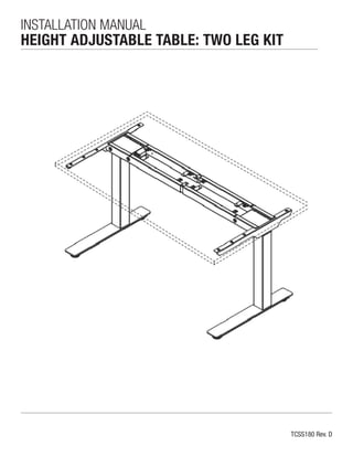
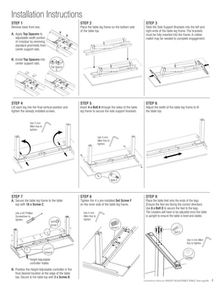
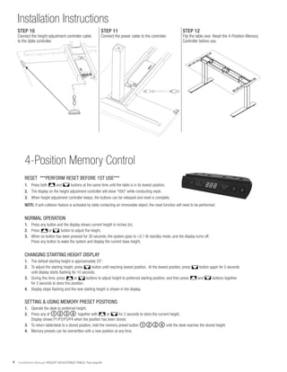
TCSS180 Rev. D
INSTALLATION MANUAL
HEIGHT ADJUSTABLE TABLE: TWO LEG KIT
2 Installation Manual: HEIGHT ADJUSTABLE TABLE: Two Leg Kit
NUMBER ITEM QTY. TOOL REQUIRED
A
M6 x 15 Bolt
4 pieces 5mm Allen Key
B
M4 x 25
Phillips Screw 2 pieces #2 Phillips Screw Driver
C
#10 x 7/8" L
Phillips Screw 18 pieces #2 Phillips Screw Driver
D
M10 x 35 Bolt
8 pieces 5mm Allen Key
E
Leveler
4 pieces N/A
F
Set Screw
4 pieces 4mm Allen Key
G
Top Spacer
2 pieces N/A
Contents
Hardware List and Tools Required / Warnings/Disclaimer.............2
Installation Instructions - STEP 1 - STEP 8.................................3
Installation Instructions - STEP 9 - STEP 11...............................4
4-Position Memory Control........................................................4
INSTALLATION WARNINGS:
•	 Read the entire instruction manual before beginning any installation or assembly.
•	 Improper installation of this product may cause extensive property damage
	 or serious personal injury, either during or after installation.
DISCLAIMER:
•	 The manufacturer will bear no responsibility for any damages of any kind
	 arising from improper installation of this product.
•	 Work surfaces will vary widely and the ultimate method of installing
	 is out of the manufacturers control. It is imperative that the installer consult
	 the work surface installation guide to ensure that it can safely handle the
	 applied load.
ADJUSTMENT NOTIFICATION:
•	 Routine maintenance checks and adjustments are suggested to properly
	 support the quality and optimal performance of this product.
•	 Over tightening of bolts during installation or adjustments can damage
	 the product and affect the function and warranty.
Hardware List and Tools Required
Warnings/Disclaimers
B
10
.39
22
.87
4
.16
#10X7/8"L
W
OOD
SCREW
3Installation Manual: HEIGHT ADJUSTABLE TABLE: Two Leg Kit
Installation Instructions
STEP 2
Place the table leg frame on the bottom side
of the table top.
STEP 5
Insert 4 x Bolt A through the sides of the table
leg frame to secure the side support brackets.
STEP 8
Tighten the 4 x pre-installed Set Screw F
on the inner side of the table leg frame.
STEP 3
Slide the Side Support Brackets into the left and
right ends of the table leg frame. The brackets
must be fully inserted into the frame. A rubber
mallet may be needed to complete engagement.
STEP 6
Adjust the width of the table leg frame to fit
the table top.
STEP 4
Lift each leg into the final vertical position and
tighten the already installed screws.
STEP 7
A.	 Secure the table leg frame to the table
	 top with 18 x Screw C.
Use 5 mm
Allen Key to
tighten.
Use 5 mm
Allen Key to
tighten.
Bolt A
Screw C
Use a #2 Phillips
Screwdriver to
tighten.
B.	 Position the Height Adjustable controller in the
	 final desired location at the edge of the table
	 top. Secure to the table top with 2 x Screw B.
Screw B
Use 4 mm
Allen Key to
tighten.
Screw F
Height Adjustable
controller holder.
B
10
.39
22
.87
4
.16
#10X7/8"L
WOODSCREW
STEP 9
Place the table feet onto the ends of the legs.
(Ensure the feet are facing the correct direction).
Use 8 x Bolt D to secure the feet to the legs.
The Levelers will have to be adjusted once the table
is upright to ensure the table is level and stable.
Use 5 mm Allen
Key to tighten.
Leveler
Bolt D
STEP 1
Remove base from box.
A.	Apply Top Spacers to
	 adjustable-width portion
	 of crossbar by removing
	 standard grommets from
	 center support rails.
B.	Install Top Spacers into
	 center support rails.
Top Spacer
G
4 Installation Manual: HEIGHT ADJUSTABLE TABLE: Two Leg Kit
Installation Instructions
4-Position Memory Control
RESET ***PERFORM RESET BEFORE 1ST USE***
1.	 Press both and buttons at the same time until the table is in its lowest position.
2.	 The display on the height adjustment controller will show "000" while conducting reset.
3.	 When height adjustment controller beeps, the buttons can be released and reset is complete.
NOTE: If anti-collision feature is activated by table contacting an immovable object, the reset function will need to be performed.
NORMAL OPERATION
1.	 Press any button and the display shows current height in inches (in).
2.	 Press or button to adjust the height.
3.	 When no button has been pressed for 30 seconds, the system goes to <0.1 W standby mode, and the display turns off.
	 Press any button to wake the system and display the current base height.
CHANGING STARTING HEIGHT DISPLAY
1.	 The default starting height is approximately 25".
2.	 To adjust the starting height, press button until reaching lowest position. At the lowest position, press button again for 5 seconds
	 until display starts flashing for 10 seconds.
3.	 During this time, press or buttons to adjust height to preferred starting position, and then press and buttons together
	 for 3 seconds to store this position.
4.	 Display stops flashing and the new starting height is shown in the display.
SETTING & USING MEMORY PRESET POSITIONS
1.	 Operate the desk to preferred height.
2.	 Press any of ①②③④ together with or for 2 seconds to store the current height.
	 Display shows P1/P2/P3/P4 when the position has been stored.
3.	 To return table/desk to a stored position, hold the memory preset button ①②③④ until the desk reaches the stored height.
4.	 Memory presets can be overwritten with a new position at any time.
1 2 3 4
1 2 3 4
STEP 10
Connect the height adjustment controller cable
to the table controller.
STEP 11
Connect the power cable to the controller.
STEP 12
Flip the table over. Reset the 4-Position Memory
Controller before use.
Operation Instructions for Using Hand Controls
to set Upper/Lower Limit
SET UPPER LIMIT
1.	 Operate the system and stop at the preferred height of upper limit.
2.	 Press ▲ + ▼ together, and release ▼ within 3 seconds (before it goes to reset mode)
3.	 Keep holding ▲ for 5 seconds
4.	 Beep-setting completed!
SET LOWER LIMIT
1.	 Operate the system and stop at the preferred height of upper limit.
2.	 Press ▲ + ▼ together, and release ▼ within 3 seconds (before it goes to reset mode)
3.	 Keep holding ▲ for 5 seconds
4.	 Beep-setting completed!
CLEAN UPPER LIMIT
1.	 Go the upper limit has been set
2.	 Press ▲ + ▼ together, and release ▼ within 3 seconds (before it goes to reset mode)
3.	 Keep holding ▲ for 5 seconds
4.	 Beep-cancellation completed!
CLEAN LOWER LIMIT
1.	 Go the upper limit has been set
2.	 Press ▲ + ▼ together, and release ▼within 3 seconds (before it goes to reset mode)
3.	 Keep holding ▲ for 5 seconds
4.	 Beep-cancellation completed!
RESET (LIMITATION OF RESET)
1.	 The reset position will still be the mechanical limit (TL fully retracted). After reset, the user has to extend the column
	 to be higher than the preset lower limit to operate normally
2.	 Within the range between reset positon and preset lower limit, only moving up is allowed until the height exceeds the preset lower limit.
	 (Moving down could not be operated)
3.	 There’s a beep as a reminder when the height exceeds the preset lower limit.
TCSS180 Rev. D

Installation Manual: Height Adjustable Table - Two Leg Kit

  • 1.
    TCSS180 Rev. D INSTALLATIONMANUAL HEIGHT ADJUSTABLE TABLE: TWO LEG KIT
  • 2.
    2 Installation Manual:HEIGHT ADJUSTABLE TABLE: Two Leg Kit NUMBER ITEM QTY. TOOL REQUIRED A M6 x 15 Bolt 4 pieces 5mm Allen Key B M4 x 25 Phillips Screw 2 pieces #2 Phillips Screw Driver C #10 x 7/8" L Phillips Screw 18 pieces #2 Phillips Screw Driver D M10 x 35 Bolt 8 pieces 5mm Allen Key E Leveler 4 pieces N/A F Set Screw 4 pieces 4mm Allen Key G Top Spacer 2 pieces N/A Contents Hardware List and Tools Required / Warnings/Disclaimer.............2 Installation Instructions - STEP 1 - STEP 8.................................3 Installation Instructions - STEP 9 - STEP 11...............................4 4-Position Memory Control........................................................4 INSTALLATION WARNINGS: • Read the entire instruction manual before beginning any installation or assembly. • Improper installation of this product may cause extensive property damage or serious personal injury, either during or after installation. DISCLAIMER: • The manufacturer will bear no responsibility for any damages of any kind arising from improper installation of this product. • Work surfaces will vary widely and the ultimate method of installing is out of the manufacturers control. It is imperative that the installer consult the work surface installation guide to ensure that it can safely handle the applied load. ADJUSTMENT NOTIFICATION: • Routine maintenance checks and adjustments are suggested to properly support the quality and optimal performance of this product. • Over tightening of bolts during installation or adjustments can damage the product and affect the function and warranty. Hardware List and Tools Required Warnings/Disclaimers B 10 .39 22 .87 4 .16 #10X7/8"L W OOD SCREW
  • 3.
    3Installation Manual: HEIGHTADJUSTABLE TABLE: Two Leg Kit Installation Instructions STEP 2 Place the table leg frame on the bottom side of the table top. STEP 5 Insert 4 x Bolt A through the sides of the table leg frame to secure the side support brackets. STEP 8 Tighten the 4 x pre-installed Set Screw F on the inner side of the table leg frame. STEP 3 Slide the Side Support Brackets into the left and right ends of the table leg frame. The brackets must be fully inserted into the frame. A rubber mallet may be needed to complete engagement. STEP 6 Adjust the width of the table leg frame to fit the table top. STEP 4 Lift each leg into the final vertical position and tighten the already installed screws. STEP 7 A. Secure the table leg frame to the table top with 18 x Screw C. Use 5 mm Allen Key to tighten. Use 5 mm Allen Key to tighten. Bolt A Screw C Use a #2 Phillips Screwdriver to tighten. B. Position the Height Adjustable controller in the final desired location at the edge of the table top. Secure to the table top with 2 x Screw B. Screw B Use 4 mm Allen Key to tighten. Screw F Height Adjustable controller holder. B 10 .39 22 .87 4 .16 #10X7/8"L WOODSCREW STEP 9 Place the table feet onto the ends of the legs. (Ensure the feet are facing the correct direction). Use 8 x Bolt D to secure the feet to the legs. The Levelers will have to be adjusted once the table is upright to ensure the table is level and stable. Use 5 mm Allen Key to tighten. Leveler Bolt D STEP 1 Remove base from box. A. Apply Top Spacers to adjustable-width portion of crossbar by removing standard grommets from center support rails. B. Install Top Spacers into center support rails. Top Spacer G
  • 4.
    4 Installation Manual:HEIGHT ADJUSTABLE TABLE: Two Leg Kit Installation Instructions 4-Position Memory Control RESET ***PERFORM RESET BEFORE 1ST USE*** 1. Press both and buttons at the same time until the table is in its lowest position. 2. The display on the height adjustment controller will show "000" while conducting reset. 3. When height adjustment controller beeps, the buttons can be released and reset is complete. NOTE: If anti-collision feature is activated by table contacting an immovable object, the reset function will need to be performed. NORMAL OPERATION 1. Press any button and the display shows current height in inches (in). 2. Press or button to adjust the height. 3. When no button has been pressed for 30 seconds, the system goes to <0.1 W standby mode, and the display turns off. Press any button to wake the system and display the current base height. CHANGING STARTING HEIGHT DISPLAY 1. The default starting height is approximately 25". 2. To adjust the starting height, press button until reaching lowest position. At the lowest position, press button again for 5 seconds until display starts flashing for 10 seconds. 3. During this time, press or buttons to adjust height to preferred starting position, and then press and buttons together for 3 seconds to store this position. 4. Display stops flashing and the new starting height is shown in the display. SETTING & USING MEMORY PRESET POSITIONS 1. Operate the desk to preferred height. 2. Press any of ①②③④ together with or for 2 seconds to store the current height. Display shows P1/P2/P3/P4 when the position has been stored. 3. To return table/desk to a stored position, hold the memory preset button ①②③④ until the desk reaches the stored height. 4. Memory presets can be overwritten with a new position at any time. 1 2 3 4 1 2 3 4 STEP 10 Connect the height adjustment controller cable to the table controller. STEP 11 Connect the power cable to the controller. STEP 12 Flip the table over. Reset the 4-Position Memory Controller before use.
  • 5.
    Operation Instructions forUsing Hand Controls to set Upper/Lower Limit SET UPPER LIMIT 1. Operate the system and stop at the preferred height of upper limit. 2. Press ▲ + ▼ together, and release ▼ within 3 seconds (before it goes to reset mode) 3. Keep holding ▲ for 5 seconds 4. Beep-setting completed! SET LOWER LIMIT 1. Operate the system and stop at the preferred height of upper limit. 2. Press ▲ + ▼ together, and release ▼ within 3 seconds (before it goes to reset mode) 3. Keep holding ▲ for 5 seconds 4. Beep-setting completed! CLEAN UPPER LIMIT 1. Go the upper limit has been set 2. Press ▲ + ▼ together, and release ▼ within 3 seconds (before it goes to reset mode) 3. Keep holding ▲ for 5 seconds 4. Beep-cancellation completed! CLEAN LOWER LIMIT 1. Go the upper limit has been set 2. Press ▲ + ▼ together, and release ▼within 3 seconds (before it goes to reset mode) 3. Keep holding ▲ for 5 seconds 4. Beep-cancellation completed! RESET (LIMITATION OF RESET) 1. The reset position will still be the mechanical limit (TL fully retracted). After reset, the user has to extend the column to be higher than the preset lower limit to operate normally 2. Within the range between reset positon and preset lower limit, only moving up is allowed until the height exceeds the preset lower limit. (Moving down could not be operated) 3. There’s a beep as a reminder when the height exceeds the preset lower limit. TCSS180 Rev. D