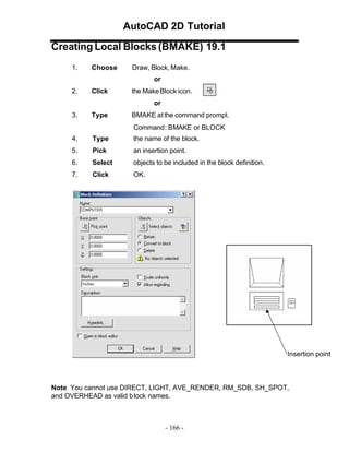
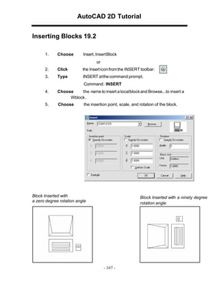
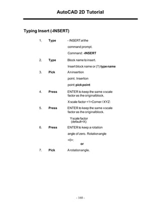
This document is a tutorial on managing blocks and attributes in AutoCAD 2D, detailing processes such as creating local blocks, inserting blocks, controlling block properties, using the wblock command, purging unused elements, and defining and editing attributes. It provides step-by-step instructions for various commands including 'bmake', 'insert', and 'attdef', as well as options for attribute management. Additionally, it covers how to extract and manage attributes using built-in tools and integrates with external software like Excel for data handling.


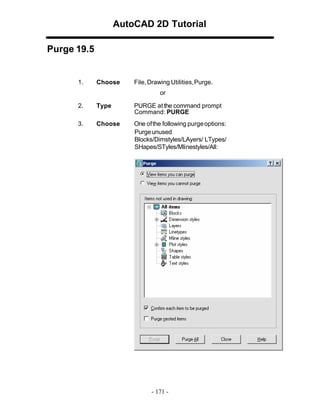
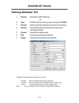
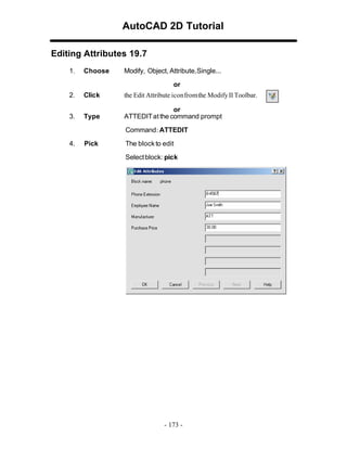
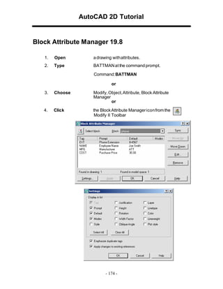
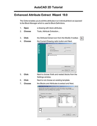


![Lect 1 Number systems and base conversions. [Autosaved].pptx](https://cdn.slidesharecdn.com/ss_thumbnails/lect1numbersystemsandbaseconversions-260111134109-67c2d865-thumbnail.jpg?width=640&height=640&fit=bounds)


