Process Control Instruments & Automation Guide
•
1 like•454 views

This document provides information on the ELGWR-40 guided wave radar level sensor. It can continuously measure liquid level and detect point level using time domain reflectometry (TDR) technology. The sensor outputs an analog signal for continuous level measurement and can output switching signals for point level detection. It has a modular probe design that allows different probe types to be used for various applications and liquid characteristics. The document describes the measurement principle, components, probe types, mounting considerations, configuration, and specifications.

Recommended
Recommended
More Related Content
What's hot
What's hot (19)
Viewers also liked
Viewers also liked (20)
Similar to Process Control Instruments & Automation Guide
Similar to Process Control Instruments & Automation Guide (20)
More from NK Instruments Pvt. Ltd.
More from NK Instruments Pvt. Ltd. (20)
Recently uploaded
Recently uploaded (20)
Process Control Instruments & Automation Guide
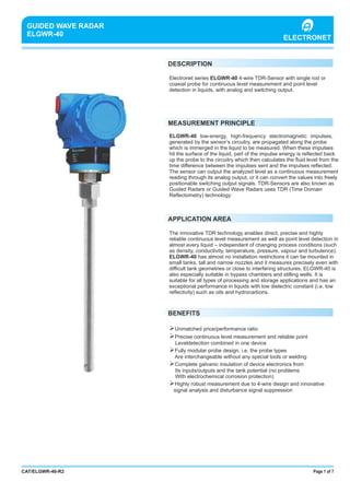
- 1. PROCESS CONTROL INSTRUMENTS & AUTOMATION Page 1 of 7CAT/ELGWR-40-R2 GUIDED WAVE RADAR ELGWR-40 Electronet series ELGWR-40 4-wire TDR-Sensor with single rod or coaxial probe for continuous level measurement and point level detection in liquids, with analog and switching output. MEASUREMENT PRINCIPLE DESCRIPTION ELGWR-40 low-energy, high-frequency electromagnetic impulses, generated by the sensor’s circuitry, are propagated along the probe which is immerged in the liquid to be measured. When these impulses hit the surface of the liquid, part of the impulse energy is reflected back up the probe to the circuitry which then calculates the fluid level from the time difference between the impulses sent and the impulses reflected. The sensor can output the analyzed level as a continuous measurement reading through its analog output, or it can convert the values into freely positionable switching output signals. TDR-Sensors are also known as Guided Radars or Guided Wave Radars uses TDR (Time Domain Reflectometry) technology: APPLICATION AREA The innovative TDR technology enables direct, precise and highly reliable continuous level measurement as well as point level detection in almost every liquid – independent of changing process conditions (such as density, conductivity, temperature, pressure, vapour and turbulence). ELGWR-40 has almost no installation restrictions it can be mounted in small tanks, tall and narrow nozzles and it measures precisely even with difficult tank geometries or close to interfering structures. ELGWR-40 is also especially suitable in bypass chambers and stilling wells. It is suitable for all types of processing and storage applications and has an exceptional performance in liquids with low dielectric constant (i.e. low reflectivity) such as oils and hydrocarbons. BENEFITS ØUnmatched price/performance ratio ØPrecise continuous level measurement and reliable point Leveldetection combined in one device ØFully modular probe design, i.e. the probe types Are interchangeable without any special tools or welding ØComplete galvanic insulation of device electronics from Its inputs/outputs and the tank potential (no problems With electrochemical corrosion protection) ØHighly robust measurement due to 4-wire design and innovative signal analysis and disturbance signal suppression ELECTRONET
- 2. Fig.1: sensor components Fig. 2: probe type considerations Housing Feedthrough Probe Page 2 of 7CAT/ELGWR-40-R2 Fig. 3: modular probe design rod counter nut ferrule o-ring lock nut spacer tube SENSOR COMPONENTS AND PROBE TYPE ELGWR-40 consists of three major components: housing,feed through, and probe. The only components that are exposed to the atmosphere inside the tank are probe and the part of the feed through below the hexagon. The housing contains the sensor’s electronics and input/output terminals and has no contact to the tank atmosphere. The so called feed through is mounted into the bottom of the housing and serves two main purposes: its outer threaded metal bushing securely connects the sensor to the tank and its inner components guide the high frequency measurement signal from the electronics through the tank wall into the tank and back. The probe is mounted onto the bottom of the feed through and gets immerged into the liquid inside the tank; the high- frequency measurement signal is propagated along the probe. ELGWR- 40 has a flexible modular concept: any probe can be used with any housing since they are joined together by one universal feed through. To meet various application requirements, ELGWR-40 has two different probe types: a single rod probe and a coaxial probe. The single rod probe is suitable for a very wide range of applications and liquids, but the signal has a wider detection radius around the rod. Thus, it is more responsive for measurement signal disturbances which can be easily overcome by observing a few mounting considerations and making simple configuration adjustments to the sensor. The single rod probe is also recommended for installation in bypass chambers and stilling wells, which basically act together with the rod as a big coaxial probe. In the coaxial probe, the high-frequency measurement signal is completely contained within the outer tube.Thus, the coaxial probe is immune against any external conditions and interfering objects outside its tube which could otherwise cause disturbances of the measurement signal. This makes the coaxial probe the ideal solution for a hasslefree ‘drop-in anywhere’ installation; ensuring reliable measurement under almost any application condition. The concentrated signal within the tube also makes the coaxial probe the ideal choice for measuring low reflectivity liquids (i.e. low dielectric constant) such as oils and hydrocarbons. The coaxial probe is recommended for the use with clean liquids only and cannot be used with viscous, crystallizing, adhesive, coating, or sticky liquids; fibrous liquids, sludge, slurry, pulp; any liquids containing solid particles. Such liquids might cause buildup, bridging or clogging inside the coaxial probe. The probe design of ELGWR-40 is fully modular, i.e. the probe types are interchangeable. The single rod probe actually forms the inner conductor of the coaxial probe: a standard Ø17,2mm or ." tube is mounted over the single rod probe and tightened with a very simple, yet safe, ferrule/locknut-style connection; similar to the ones widely used in standard tube fittings. SINGLE ROD PROBE PROBE MOUNTING + + Close To Internal Tank Structures Or Tank Wall + + + Non-stationary Interference Targets, E.g. Agitator Blades + Measurement Readings At The Very Top Or Bottom Of The Tank + Non-metallic Tanks + Bypass Chambers And Stilling Wells • LIQUID CHARACTERISTICS + Viscous, Crystallizing, Adhesive, Coating, Or Sticky Liquids - - Liquids Containing Solid Particles - Cleanability Of Probe - COAXIAL PROBE Tall And Narrow Nozzles Difficult Tank Or Nozzle Geometries Probe Might Move And Touch Internal Tank Structures Or Tank Wall Liquid Spray May Touch Probe Above The Liquid Surface Measuring Low Reflectivity Liquids (i.e. Dielectric Constant) Fibrous Liquids, Sludge, Slurry, Pulp • • • - - - • • + • + + + + + = Recommended = Possible, maybe with configuration and/ or mounting adjustments = not recommended-
- 3. Figure 5: mounting gasket socket mounting gasket gasket Page 3 of 7CAT/ELGWR-40-R2 Fig. 4: probe length and measuring range PROBE LENGTH AND MEASURING RANGE The reference point for definition of the probe length [L] is always the sealing surface of the connection thread. The probe length [L] is an important mechanical dimension which is needed to make sure the probe physically fits into the tank at the anticipated mounting location; it is not equal to the actual easuring range [M] of the sensor! TDR level sensors have small inactive areas at top [L1] and bottom [L2] of the probe. Those are due to the presence of unavoidable signal disturbances at both ends of the probe. In these inactive areas the measurements are non-linear or have reduced accuracy. Therefore, it is not recommended to actually measure level within those inactive areas. Their length depends on the probe type and the reflectivity (i.e. dielectric constant) of the liquid to be measured. The measuring range [M] of ELGWR-40 extends between the top and bottom inactive areas of the probe; this is the area in which ELGWR-40 will have the specified measurement performance. It is recommended that the maximum and minimum liquid levels to be measured in the tank are actually within the measuring range [M] of the sensor. The span between the lower range value [4mA] and the upper range value [20mA] of the analog current output is equal to 0...100% of your continuous level measurement reading. It is recommended that the span between those two range values stays within the measuring range [M]. The location of the switching point [S] of the switching output can also be freely positioned within the measuring range [M]. Fixed hysteresis or separate upper and lower thresholds can be defined for the switching output. MOUNTING ELGWR-40 is mounted vertically to the tank via its connection thread, which is screwed directly into a standard threaded tank connection, i.e. weld-in socket, or it can be screwed into a flange, which is then connected to a tank nozzle. The customer has to ensure proper temperature and pressure ratings for his application and has to select the appropriate seal to connect the sensor (ELGWR-40 comes with a Klingersil C-4400 gasket). ELGWR-40 is very well suited for external mounting into a bypass chamber. Thus, ELGWR-40 is also the ideal replacement for chamber-mounted displacers: simply remove the displacer, keep its existing chamber and fit a ELGWR-40 into it. The powerful disturbance signal suppression features of ELGWR-40 ensures easy retrofitting and reliable measurement in almost any existing displacer chamber. The probes should be installed so that they are not directly impacted by liquids flowing out of the filling inlet. They should neither touch nor sway towards other objects inside the tank or the tank/nozzle walls; e.g. by agitator swirls. In applications with very strong fluid movements, which can also cause excessive lateral force on the probe, it is recommended to fix the probe. The single rod is suitable for a very wide range of applications and liquids, but the signal has a wider detection radius around the rod. Thus, it is more responsive for measurement signal disturbances which can be easily overcome by observing a few mounting considerations and making simple configuration adjustments to the sensor; in most cases it is enough to activate and utilize the powerful disturbance signal suppression features of ELGWR-40.
- 4. Page 4 of 7CAT/ELGWR-40-R2 However, those work most efficiently on stationary interference targets like tall and narrow nozzles or close-by objects. In case that non stationary interference targets close to the single rod probe, like slowly rotating agitator blades, cause problems with the measurement, it is recommended to use the coaxial probe. In any case, the single rod probe should never get in direct contact with the tank/nozzle wall or other objects in the tank. The coaxial probe does not have restrictions regarding mounting position, tank connection, and proximity to the tank wall or other objects inside the tank. The coaxial probe is recommended for installing ELGWR-40 into a non-metallic tank or open pit. If that is not possible, a single rod probe can be used when ELGWR-40 is mounted into at least a DN50 metal flange or screwed into a metal Figure 7: electrical connection power supply computer ELECTRICAL CONNECTION ELGWR-40 is a 4-wire system: a set of 2 wires for the power supply and separate sets of 2 wires for each output. The wires are connected to the sensor electronic inside the housing via a screwless, cage clamp terminal block for stranded and solid wires 0.5…2mm² / AWG 22...14. The housing has two cable entries and can be ordered with assembled standard screw plugs and cable glands. Nevertheless, the customer has to confirm the suitability of those cable glands for his specific application requirements and cabling; and replace them when necessary. IP68- rated screw plugs and cable glands have to be properly mounted (with rubber washers underneath) and have to be properly tightened around cable of suitable type and diameter to nsure the Ip68 rating of the housing.ELGWR-40’s electronic is galvanically completely insulated from its inputs/outputs and the tank potential; thus avoiding any problems from electrochemical corrosion protection of the tank. CONFIGURATION Basic configuration of ELGWR-40 can be done directly on the device via a DIP switch, a single push button and visual feedback from an LED. All settings required to get ELGWR-40 fully operational can be performed directly on the device; or ELGWR- 40 can be ordered completely pre- configured. For greater convenience, remote configuration, and extensive diagnostics a simple EXCEL spread sheet is provided through which the configuration can be done. A standard HART modem is required for communication between computer and sensor. Communication happens via a digital HART signal that is superimposed onto the analog 4…20mA signal of the current output. Fig. 6: mounting considerations Nozzle Diameter -1 >50mm Nozzle Height - <300mm Clearance To Tank Wall Or Other Internal Objects - >100mm Clearance Between Probe End And Tank Bottom - >2mm Diameter Of Bypass Chamber / Stilling Well -2 >25mm SINGLE ROD PROBE COAXIAL PEOBE = not recommended Enough diameter to fit in the coaxial tube (F17,2mm) Enough diameter to fit in the coaxial tube (F17,2mm) and enough room around the probe for the liquid to flow in and out of the bypass chamber/ stilling well
- 5. Page 5 of 7CAT/ELGWR-40-R2 ELECTRICAL SPECIFICATIONS 4 wire system Output function Analog output (active) Total load resistance Continuos level measurement through analog output and point level detection through switching output. Current output 4...20 mA the span between the lower range value (4 mA) and the upper range value (20mA) is equal to 0...100% of the contentious level measurement reading. It is recommended that the span between those two range values stays within the measuring range (M) <500Ù: HART resistor approx. 250Ù + load resistance approx. 250Ù if the current output is connected to a device with an inner resistance of approx. 250Ù, then there is no additional, external HART resistor necessary. In that case, the HART modem is connected in parallel to the current output wires Lower range value Upper range value Response time Temperature drift Switching output DC PNP (active) Load current Signal voltage HIGH Signal voltage LOW Response time Supply voltage Current consumption Start-up time Cable terminals 4.0mA (span 0%) 20.0mA (span 100%) 0.5s (default), 2s, 5s (selectable) <0,2mm/K change in ambient temperature NC or NO (short-circuit protected) <200mA 2V 0V to 1V <100ms 12 to 30VDC (reverse-polarity protected) <70mA at 24VDC (no burden) <6s screwless, cage clamp terminal block for stranded and solid wires 0.5…2mm² / AWG 22...14 the usage of cable end sleeves with insulation collar is not recommended MEASUREMENT SPECIFICATIONS Accuracy Repeatability Resolution ±3mm <2mm <1mm Probe type Probe length [L] Inactive area top [I1] Inactive areas bottom [I2] Measuring range [M] Switching point [S] single rod Ø6mm coaxial Ø17,2mm (standard tube: NPS. ", 10S) single rod probe: 100...3.000mm longer length on request coaxial probe: 100…6.000mm can be ordered in 1mm increments the reference point is always the sealing surface of the connection thread (see dimensional drawings) single rod probe, e=80: 50mm coaxial probe, e=80: 30mmr r single rod probe, e=2: 80mm coaxial probe, e=2: 50mmr r single rod probe, e=80: 10mm coaxial probe, e=80: 10mmr r single rod probe, e=2: 50mm coaxial probe, e=2: 50mmr r Probe length [L] less both inactive areas at top and bottom [I1 and I2] in this range EEPL will have the specified measurement performance. It is recommended that the maximum and minimum liquid levels to be measured in the tank are actually within the measuring range [M] of the sensor Freely positionable within the measuring range [M] hysteresis can be set by defining separate upper and lower thresholds; if those are set at the same position, the minimum hysteresis of 3mm applies Reference condition: dielectric constant [e]=80, water surface,r tank F1m, DN200 metal flange
- 6. Page 6 of 7CAT/ELGWR-40-R2 APPLICATION SPECIFICATIONS continuous level measurement and point level detection in liquids Dielectric constant [ ]er Conductivity Density single rod probe: >1.8 coaxial probe:>1.4 no restrictions Dynamic viscosity Application temperature Ambient temperature Application pressure Velocity of level change Interface (e.g. oil on top of water) single rod probe : <5.000mPa s = 5.000cP coaxial probe : <500mPa s = 500cP -40°C to +150°C operation: -25°C to +80°C storage: -40°C to +85°C -1bar to 40bar <1.000mm/s an oil layer of <70mm thickness on top of water is not detected by the sensor; in this case the sensor will detect only the water level at a slightly lower position than actual. From an oil layer thickness >70mm onwards, the sensor detects the total level, including the oil layer, according to specifications no restrictions MECHANICAL SPECIFICATIONS Conductivity Density single rod probe : 1.4404 / 316L and PEEK coaxial probe : 1.4404 / 316L, PEEK and o-ring seal: EPDM or FKM (Viton) other o-ring materials on request gasket at connection thread : Klingersil C-4400, 2mm thick no restrictions Dynamic viscosity Application temperature Ambient temperature Application pressure Velocity of level change Interface (e.g. oil on top of water) single rod probe : <5.000mPa s = 5.000cP coaxial probe : <500mPa s = 500cP -40°C to +150°C operation: -25°C to +80°C storage: -40°C to +85°C -1bar to 40bar <1.000mm/s an oil layer of <70mm thickness on top of water is not detected by the sensor; in this case the sensor will detect only the water level at a slightly lower position than actual. From an oil layer thickness >70mm onwards, the sensor detects the total level, including the oil layer, according to specifications CMRI Certified,Flame Proof,die Cast Aluminium Lm6, Housing no restrictions Material expose to tank atmosphere Material housing Housing rating Cable entries /Cable gland Connection thread [CT] G¾A (wrench size 32mm) other connection threads on request IP-66 M20 x 1.5 Pitch (F) 1) without Display: 100 mm (H) X 102 mm (W) 2) with Display: 130 mm (H) X 220 mm (W) X 190 mm (D)
- 7. NK Instruments Pvt. Ltd.B-501/504, 5th floor, Raunak Arcade, Near THC Hospital, Gokhale Road, Naupada, Thane(W) 400602. Maharashtra INDIA Telefax Nos.: 91-22-25301330 / 31 / 32 E-Mail: sales@nkinstruments.com Web: http://www.nkinstruments.com Skype: nitinkelkarskype Gtalk: nkinstruments2006 Authorised Dealer ORDERING INFORMATION DIMENSIONS IN MM 130mm 104mm 119mm71mm DIMENSIONAL DETAILS Page 7 of 7CAT/ELGWR-40-R2 *Accuracy defined at lab conditions. *Due to our continuous product revisions, Design, Specifications and Model Number are subject to change without notice. SERIES 02 0202 0902 02 04 06 07 02 01 0101 01 01 02 01B ED G01 0201 02A C F 01 01 03 05 01 ELGWR-40 Single Rod 1 mtr. 3 mtr. 03 G ¾” A 8 mtr. Aluminium Coaxial 2 mtr. 6 mtr. 15 mtr. 20 mtr. SS316 SS316L ¾” NPT EPDM Probe Type Probe length Electronics enclosure Wetted parts Process connection ‘O’ ring material Display Hyst C 2”flange ASA 150 FKM (viton) 03 PTFE lined 8x1 LCD None