UNIT-V
I/O Interface Unit,Types of ports (I/O port, Network
Port, USB port, Serial and Parallel Port), Concept of I/O
bus, Isolated I/O versus Memory-Mapped I/O.
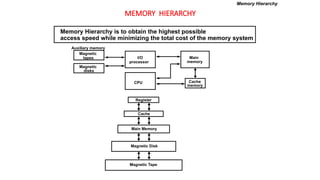
Memory Hierarchy, Main Memory (RAM and ROM
chips, Logical and Physical Addresses, Memory
Address Map, Memory Connection to
CPU),Associative Memory, Cache Memory,DMA
Transfer,modes of data transfer.
11.
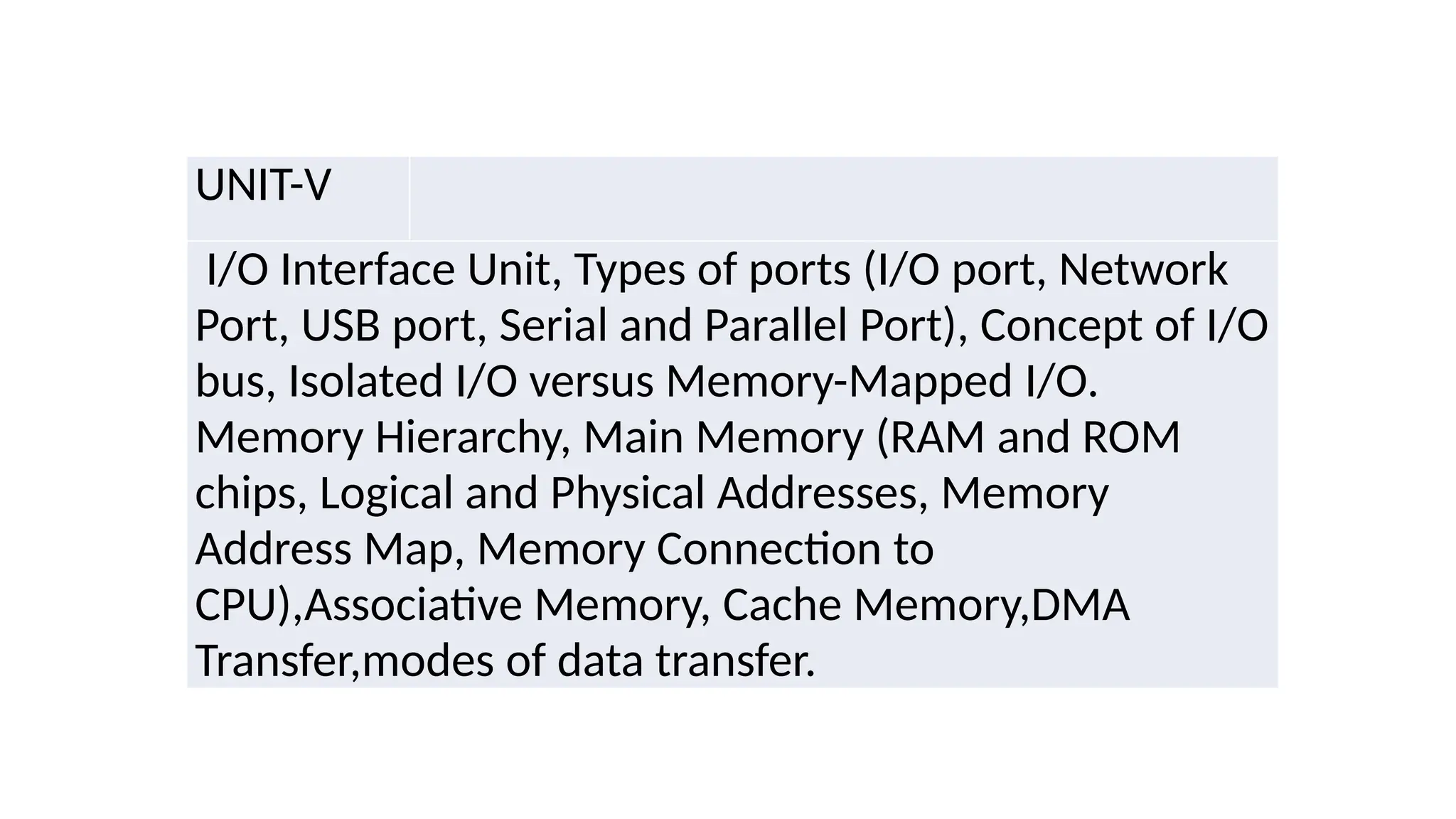
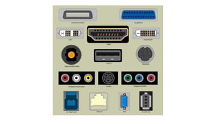
Introduction to Ports
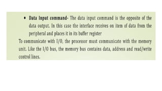
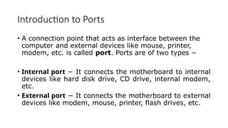
•A connection point that acts as interface between the
computer and external devices like mouse, printer,
modem, etc. is called port. Ports are of two types −
• Internal port − It connects the motherboard to internal
devices like hard disk drive, CD drive, internal modem,
etc.
• External port − It connects the motherboard to external
devices like modem, mouse, printer, flash drives, etc.
13.
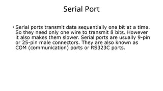
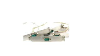
Serial Port
• Serialports transmit data sequentially one bit at a time.
So they need only one wire to transmit 8 bits. However
it also makes them slower. Serial ports are usually 9-pin
or 25-pin male connectors. They are also known as
COM (communication) ports or RS323C ports.
15.
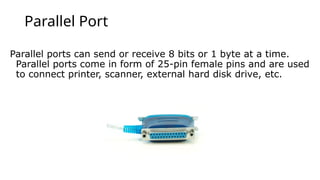
Parallel Port
Parallel portscan send or receive 8 bits or 1 byte at a time.
Parallel ports come in form of 25-pin female pins and are used
to connect printer, scanner, external hard disk drive, etc.
16.
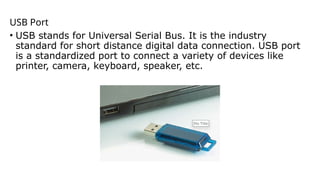
USB Port
• USBstands for Universal Serial Bus. It is the industry
standard for short distance digital data connection. USB port
is a standardized port to connect a variety of devices like
printer, camera, keyboard, speaker, etc.
17.
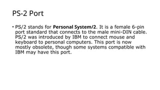
PS-2 Port
• PS/2stands for Personal System/2. It is a female 6-pin
port standard that connects to the male mini-DIN cable.
PS/2 was introduced by IBM to connect mouse and
keyboard to personal computers. This port is now
mostly obsolete, though some systems compatible with
IBM may have this port.
18.
Infrared Port
Infrared portis a port that enables wireless exchange of data
within a radius of 10m. Two devices that have infrared ports
are placed facing each other so that beams of infrared lights
can be used to share data.
19.
Bluetooth Port
Bluetooth isa telecommunication specification that
facilitates wireless connection between phones, computers
and other digital devices over short range wireless
connection. Bluetooth port enables synchronization
between Bluetooth-enabled devices. There are two types of
Bluetooth ports −
• Incoming − It is used to receive connection from Bluetooth
devices.
• Outgoing − It is used to request connection to other
Bluetooth devices.
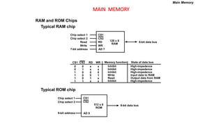
MAIN MEMORY
RAM andROM Chips
Typical RAM chip
Typical ROM chip
Chip select 1
Chip select 2
Read
Write
7-bit address
CS1
CS2
RD
WR
AD 7
128 x 8
RAM
8-bit data bus
CS1 CS2 RD WR
0 0 x x
0 1 x x
1 0 0 0
1 0 0 1
1 0 1 x
1 1 x x
Memory function
Inhibit
Inhibit
Inhibit
Write
Read
Inhibit
State of data bus
High-impedence
High-impedence
High-impedence
Input data to RAM
Output data from RAM
High-impedence
Chip select 1
Chip select 2
9-bit address
CS1
CS2
AD 9
512 x 8
ROM
8-bit data bus
Main Memory
23.
MEMORY ADDRESS MAP
MemoryConnection to CPU
- RAM and ROM chips are connected to a CPU
through the data and address buses
- The low-order lines in the address bus select
the byte within the chips and other lines in the
address bus select a particular chip through
its chip select inputs
Main Memory
24.
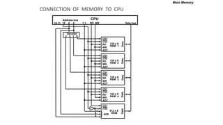
CONNECTION OF MEMORYTO CPU
Main Memory
}
CS1
CS2
RD
WR
AD7
128 x 8
RAM 1
CS1
CS2
RD
WR
AD7
128 x 8
RAM 2
CS1
CS2
RD
WR
AD7
128 x 8
RAM 3
CS1
CS2
RD
WR
AD7
128 x 8
RAM 4
Decoder
3 2 1 0
WR
RD
9 8 7-1
10
16-11
Address bus
Data bus
CPU
CS1
CS2
512 x 8
ROM
AD9
1- 7
9
8
Data
Data
Data
Data
Data
25.
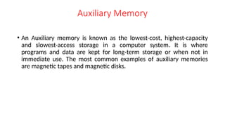
Auxiliary Memory
• AnAuxiliary memory is known as the lowest-cost, highest-capacity
and slowest-access storage in a computer system. It is where
programs and data are kept for long-term storage or when not in
immediate use. The most common examples of auxiliary memories
are magnetic tapes and magnetic disks.
26.
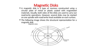
Magnetic Disks
Amagnetic disk is a type of memory constructed using a
circular plate of metal or plastic coated with magnetized
materials. Usually, both sides of the disks are used to carry out
read/write operations. However, several disks may be stacked
on one spindle with read/write head available on each surface.
The following image shows the structural representation for a
magnetic disk.
27.
Magnetic Tape
Magnetictape is a storage medium that allows data archiving,
collection, and backup for different kinds of data. The magnetic tape is
constructed using a plastic strip coated with a magnetic recording
medium.
The bits are recorded as magnetic spots on the tape along several
tracks. Usually, seven or nine bits are recorded simultaneously to form a
character together with a parity bit.
Magnetic tape units can be halted, started to move forward or in
reverse, or can be rewound. However, they cannot be started or
stopped fast enough between individual characters. For this reason,
information is recorded in blocks referred to as records.
28.
Associative Memory
inassociative memory can be considered as a memory unit
whose stored data can be identified for access by the content of
the data itself rather than by an address or memory location.
Associative memory is often referred to as Content Addressable
Memory (CAM).
When a write operation is performed on associative memory,
no address or memory location is given to the word. The
memory itself is capable of finding an empty unused location to
store the word.
On the other hand, when the word is to be read from an
associative memory, the content of the word, or part of the
word, is specified. The words which match the specified content
are located by the memory and are marked for reading.
The following diagram shows the block representation of an
Associative memory.
29.
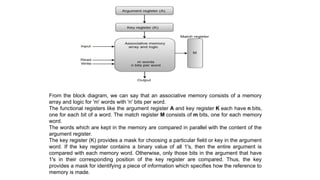
From the blockdiagram, we can say that an associative memory consists of a memory
array and logic for 'm' words with 'n' bits per word.
The functional registers like the argument register A and key register K each have n bits,
one for each bit of a word. The match register M consists of m bits, one for each memory
word.
The words which are kept in the memory are compared in parallel with the content of the
argument register.
The key register (K) provides a mask for choosing a particular field or key in the argument
word. If the key register contains a binary value of all 1's, then the entire argument is
compared with each memory word. Otherwise, only those bits in the argument that have
1's in their corresponding position of the key register are compared. Thus, the key
provides a mask for identifying a piece of information which specifies how the reference to
memory is made.
30.
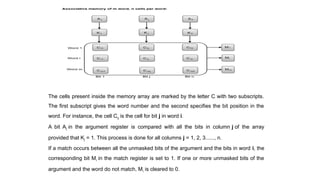
The cells presentinside the memory array are marked by the letter C with two subscripts.
The first subscript gives the word number and the second specifies the bit position in the
word. For instance, the cell Cij is the cell for bit j in word i.
A bit Aj in the argument register is compared with all the bits in column j of the array
provided that Kj = 1. This process is done for all columns j = 1, 2, 3......, n.
If a match occurs between all the unmasked bits of the argument and the bits in word i, the
corresponding bit Mi in the match register is set to 1. If one or more unmasked bits of the
argument and the word do not match, Mi is cleared to 0.
31.
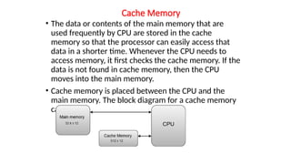
Cache Memory
• Thedata or contents of the main memory that are
used frequently by CPU are stored in the cache
memory so that the processor can easily access that
data in a shorter time. Whenever the CPU needs to
access memory, it first checks the cache memory. If the
data is not found in cache memory, then the CPU
moves into the main memory.
• Cache memory is placed between the CPU and the
main memory. The block diagram for a cache memory
can be represented as:
32.
The cache isthe fastest component in the memory hierarchy and
approaches the speed of CPU components.
The basic operation of a cache memory is as follows:
When the CPU needs to access memory, the cache is examined. If the
word is found in the cache, it is read from the fast memory.
If the word addressed by the CPU is not found in the cache, the main
memory is accessed to read the word.
A block of words one just accessed is then transferred from main
memory to cache memory. The block size may vary from one word (the
one just accessed) to about 16 words adjacent to the one just accessed.
The performance of the cache memory is frequently measured in terms
of a quantity called hit ratio.
When the CPU refers to memory and finds the word in cache, it is said
to produce a hit.
If the word is not found in the cache, it is in main memory and it counts
as a miss.
The ratio of the number of hits divided by the total CPU references to
memory (hits plus misses) is the hit ratio.
33.
Virtual Memory
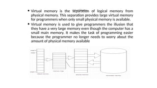
Virtualmemory is the separation of logical memory from
physical memory. This separation provides large virtual memory
for programmers when only small physical memory is available.
Virtual memory is used to give programmers the illusion that
they have a very large memory even though the computer has a
small main memory. It makes the task of programming easier
because the programmer no longer needs to worry about the
amount of physical memory available
34.
the virtualmemory model provides decoupling of addresses
used by the program (virtual) and the memory addresses
(physical). Therefore, the definition of virtual memory can be
stated as, “ The conceptual separation of user logical
memory from physical memory in order to have large virtual
memory on a small physical memory”. It gives an illusion of
infinite storage, though the memory size is limited to the size
of the virtual address.
Even though the programs generate virtual addresses, these
addresses cannot be used to access the physical memory.
Therefore, the virtual to physical address translation has to
be done. This is done by the memory management unit
(MMU). The mapping is a dynamic operation, which means
that every address is translated immediately as a word is
referenced by the CPU.


![[Deck] What's New in Spark-Iceberg Integration via DSV2.pptx](https://cdn.slidesharecdn.com/ss_thumbnails/deckwhatsnewinspark-icebergintegrationviadsv2-260210005337-25955b12-thumbnail.jpg?width=640&height=640&fit=bounds)


