Download to read offline
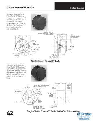
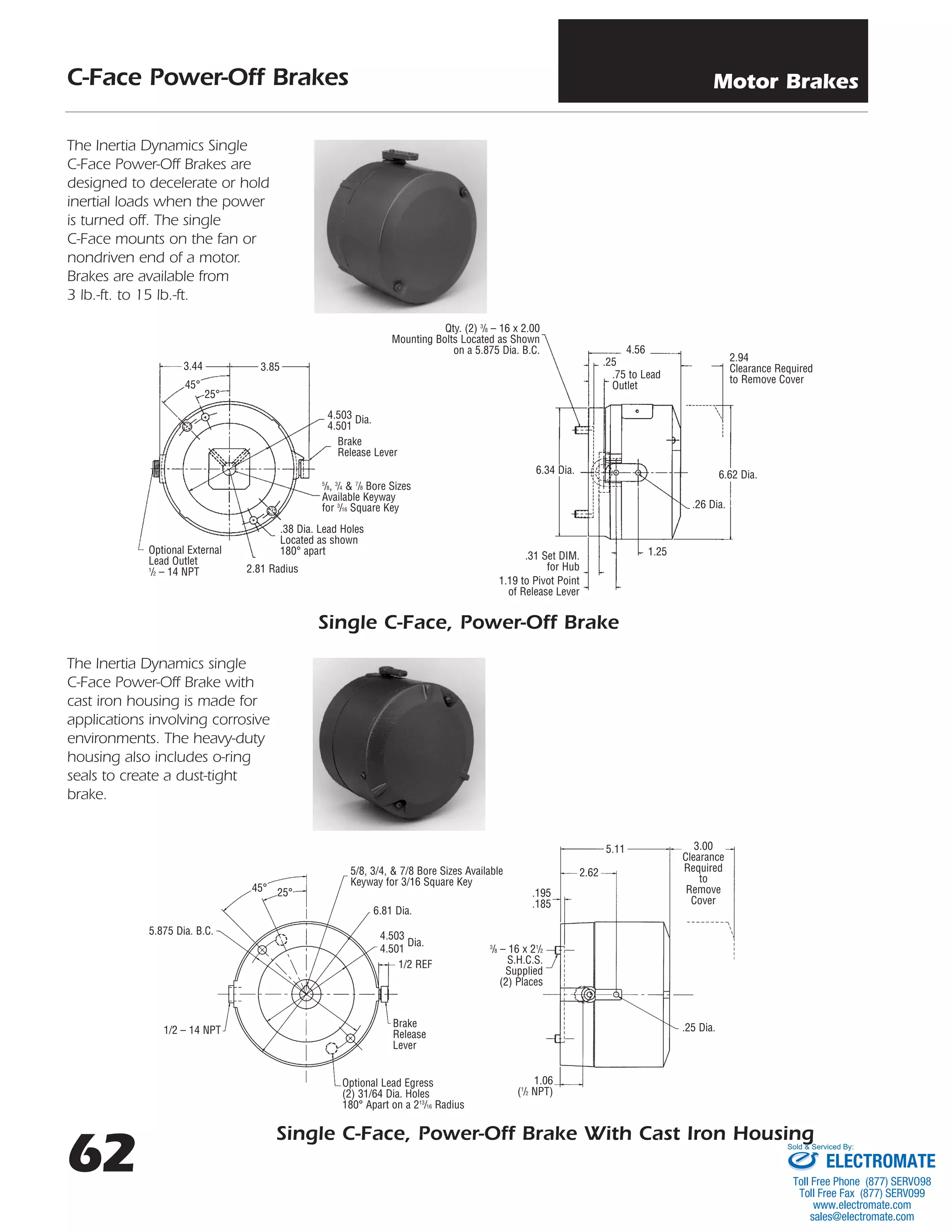
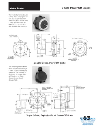

The document provides information about various C-Face power-off brakes including: - A single C-Face, power-off brake that mounts on the non-driven end of a motor and is available from 3-15 lb-ft of torque. - A single C-Face brake with a cast iron housing for corrosive environments that includes o-ring seals. - A double C-Face brake designed for use as a coupler between C-Face motors and gear reducers, with an optional foot mount kit. - An explosion-proof single C-Face brake enclosed for hazardous environments.


![Getting Started with Apache Spark: Big Data Made Simple [Free Meetup]](https://cdn.slidesharecdn.com/ss_thumbnails/apachesparkgettingstarted-260203175547-8361bcc3-thumbnail.jpg?width=640&height=640&fit=bounds)


