Inertia dynamics flangemountedbrakes_specsheet
•
0 likes•203 views

Dynacorp manufactures flange mounted brakes in various sizes from 3" to 10" for stopping applications. The document provides specifications, drawings, dimensions, parts lists, and ordering information for each brake model. It describes the Dynacorp 303, 304, 305, and 308 brake models, including their static torque ratings, recommended controls, and replacement parts.

Recommended
Recommended
More Related Content
What's hot
What's hot (14)
Similar to Inertia dynamics flangemountedbrakes_specsheet
Similar to Inertia dynamics flangemountedbrakes_specsheet (20)
More from Electromate
More from Electromate (20)
Recently uploaded
Recently uploaded (20)
Inertia dynamics flangemountedbrakes_specsheet
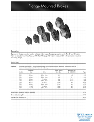
- 1. Flange Mounted Brakes H-1 Description Dynacorp® fl ange mounted brakes satisfy a wide range of stopping requirements. The 3" and 4" brakes have an outside mounting fl ange, while the 5" through 10" brakes are available with an inside or outside mounting fl ange. Section Index Products Complete information is shown for each product; including specifi cations, drawings, dimensions, parts list, recommended controls and information for ordering. Nominal Static Torque Maximum HP Model Size Style (In.-Lbs.) @ 1800 RPM Page 303 3 inch Spline Drive 60 1/2 H-2 304 4 inch Spline Drive 264 2 H-4 305 5 inch Pin Drive 684 7-1/2 H-6 305 5 inch Spline Drive 684 7-1/2 H-8 308 8 inch Pin Drive 2100 30 H-10 308 8 inch Spline Drive 2100 30 H-12 310 10 inch Pin Drive 3600 40 H-14 310 10 inch Spline Drive 3600 40 H-16 Ajusto-Gap® Armature and Hub Assembly ...................................................................................................................................H-18 Terminal Insulating Kit ...................................................................................................................................................................H-19 Zero Air Gap Accessory Kit ............................................................................................................................................................H-20 Sold & Serviced By: ELECTROMATE Toll Free Phone (877) SERVO98 Toll Free Fax (877) SERV099 www.electromate.com sales@electromate.com
- 2. H-2 "A" Bore Keyway 1/2" .125 x .062 5/8" .188 x .093 3/4" .188 x .093 Flange Mounted Brake Order Parts for Assembly No. FC303055 Armature Hub Assembly Magnet Bore Armature Plate Accessory 1/2" 5/8" 3/4" Magnet 24 Volts 303390-2 326147 303451-3 303451-5 303453-8 303353 90 Volts 303390-2 326147 303451-3 303451-5 303453-8 303354 To order, specify: 1, Armature Plate 1, Magnet Accessory 1, Armature Hub Assembly of required Bore size 1, Magnet of required Voltage For controls, see Section K. Technical Data and Torque (In. Lb.) Static Max. Coil * Rated RPM Model Wt. Torque Speed Voltage Current No. Lbs. in. lb. RPM vdc amps 0 300 600 900 1200 1500 1800 2400 3000 3600 303 .71 60 3600 90 .11 60 53 48 43 42 41 38 35 32 30 * Rated current for 90v. Customer must maintain: 1. Concentricity between mounting fl ange and shaft within .006. 2. Perpendicularity between mounting surface and shaft within .006. Refer to Section M for torque and heat dissipation curves. Flange Mounted Spline Drive Model 303 Sold Serviced By: ELECTROMATE Toll Free Phone (877) SERVO98 Toll Free Fax (877) SERV099 www.electromate.com sales@electromate.com
- 3. H- Flange Mounted Brake – Replacement Parts -A 1 4 2 Replacement Parts Item Qty. Description Part No. Item Qty. Description Part No. 1 1 Armature Plate Assy. (10 Teeth) 30390-2 2 1 Magnet Accessory 326147 3-A 1 Armature Hub Assembly 3/8 Plain Bore 303453-PB 1/2 Bore 303451-3 5/8 Bore 303451-5 3/4 Bore 303453-8 4 1 Magnet 24 Volts 30353 90 Volts 30354 Sold Serviced By: ELECTROMATE Toll Free Phone (877) SERVO98 Toll Free Fax (877) SERV099 www.electromate.com sales@electromate.com
- 4. H-4 Bore A Keyway 1/2 .125 x .062 5/8 .187 x .094 3/4 .187 x .094 7/8 .187 x .094 1 .250 x .125 Flange Mounted Brake Order Parts for Assembly No. FC304055 Armature Hub Assembly Magnet Bore Armature Plate Accessory 1/2 5/8 3/4 Magnet 24 Volts 304390-11 326146-2 303451-3 303451-5 303453-8 304353 90 Volts 304390-11 326146-2 303451-3 303451-5 303453-8 304354 To order, specify: 1, Armature Plate 1, Magnet Accessory 1, Armature Hub Assembly of required Bore size 1, Magnet of required Voltage For controls, see Section K. Technical Data and Torque (In. Lb.) Static Max. Coil * Rated RPM Model Wt. Torque Speed Voltage Current No. Lbs. in. lb. RPM vdc amps 0 300 600 900 1200 1500 1800 2400 3000 3600 304 2.5 264 3600 90 .13 264 216 192 180 168 156 156 144 132 120 * Rated current at 90v. Customer must maintain: 1. Concentricity between mounting fl ange and shaft within .006. 2. Perpendicularity between mounting surface and shaft within .006. Refer to Section M for torque and heat dissipation curves. Refer to Page H-18 for dimensions of Ajusto-gap®. Flange Mounted Spline Drive Model 304 Sold Serviced By: ELECTROMATE Toll Free Phone (877) SERVO98 Toll Free Fax (877) SERV099 www.electromate.com sales@electromate.com
- 5. H-5 Flange Mounted Brake – Replacement Parts Replacement Parts 1-C Item Qty. Description Part No. Item Qty. Description Part No. 1-A 1 Armature Plate Assembly 304390-11 10 Teeth (1/2 - 3/4 Bore) 1-C 1 Ajusto-gap® Arm. Plate Assy. 7/8 and 1 bores 304396-8 2 1 Magnet Accessory 326146-2 3-A 1 Armature Hub Assembly 1/2 Bore 303451-3 5/8 Bore 303451-5 3/4 Bore 303453-8 3-C 1 Ajusto-gap® Hub Assembly 7/8 304465-4 1 304465-5 4 1 Magnet 24 Volts 304353 90 Volts 304354 3-C 3-A 1-A 4 2 The Ajusto-gap® armature feature (1-C 3-C) can be used to give a positive release of the armature plate while maintaining a constant air gap throughout the wear life of the unit. See page H-18 for complete information. Sold Serviced By: ELECTROMATE Toll Free Phone (877) SERVO98 Toll Free Fax (877) SERV099 www.electromate.com sales@electromate.com
- 6. H-6 Inside Mount 1.19 Outside Mount 1.26 Technical Data and Torque (In. Lb.) Inside Mount 2.94 Outside Mount 3.01 Static Max. Coil * Rated RPM Model Wt. Torque Speed Voltage Current No. Lbs. in. lb. RPM vdc amps 0 300 600 900 1200 1500 1800 2400 3000 3600 305 3.5 684 3600 90 .41 684 624 564 516 468 420 384 324 288 252 * Rated current at 90v. Refer to Section M for torque and heat dissipation curves. Customer must maintain: 1. Concentricity between mounting fl ange and shaft within .006. 2. Perpendicularity between mounting surface and shaft within .006. Order Parts for Assembly No. FC305050 and FC305051 FC305050 FC305051 Armature Hub Armature Plate Magnet (1215) Taper Magnet Assembly Assembly Accessory Bushing Inside Mounted Outside Mounted 24 Volts 305450 305381 326143 326058-XX 305343 305353 90 Volts 305450 305381 326143 326058-XX 305344 305354 To order, specify: 1, Armature Hub For controls, see Section K. 1, Armature Plate Assembly 1, Magnet Accessory 1, Taper Bushing (1215) of required Bore size 1, Magnet of required Voltage for either Inside Mount or Outside Mount Flange Mounted Pin Drive Model 305 Bushing 1215 Bore ‘E’ Keyway Part No. 1/2 .500 .125 x .062 326058 - 1 9/16 .562 .125 x .062 326058 - 2 5/8 .625 .187 x .093 326058 - 3 11/16 .687 .187 x .093 326058 - 4 3/4 .750 .187 x .093 326058 - 5 13/16 .812 .187 x .093 326058 - 6 7/8 .875 .187 x .093 326058 - 7 15/16 .937 .250 x .125 326058 - 8 1 1.000 .250 x .125 326058 - 9 1-1/16 1.062 .250 x .125 326058 - 10 1-1/8 1.125 .250 x .125 326058 - 11 1-3/16 1.187 .250 x .125 326058 - 12 1-1/4 1.250 .250 x .125 326058 - 13 Flange Mounted Brake Sold Serviced By: ELECTROMATE Toll Free Phone (877) SERVO98 Toll Free Fax (877) SERV099 www.electromate.com sales@electromate.com
- 7. H-7 2 Replacement Parts 5 1 Item Qty. Description Part No. 1 1 Armature Hub Assembly 305450 2 1 Armature Plate Assembly 305381 3 1 Magnet Accessory 326143 4 1 Magnet 24 Volts, inside mounted 305343 90 Volts, inside mounted 305344 24 Volts, outside mounted 305353 90 Volts, outside mounted 305354 5 1 Taper Bushing (1215) 326058-XX Outside Mount 4 4 Inside Mount 3 Flange Mounted Brake ✽ ✽ Current design armatures are solid. Sold Serviced By: ELECTROMATE Toll Free Phone (877) SERVO98 Toll Free Fax (877) SERV099 www.electromate.com sales@electromate.com
- 8. H-8 Inside Mount 1.19 Outside Mount 1.26 Bore A Keyway 3/4 .187 x .094 7/8 .187 x .094 1 .250 x .125 1-1/8 .250 x .125 1-1/4 .250 x .125 Technical Data and Torque (In. Lb.) Flange Mounted Brake Model 305 Inside Mount 2.14 Outside Mount 2.21 Static Max. Coil * Rated RPM Flange Mounted Spline Drive Model Wt. Torque Speed Voltage Current No. Lbs. in. lb. RPM vdc amps 0 300 600 900 1200 1500 1800 2400 3000 3600 305 5.1 684 3600 90 .41 684 624 564 516 468 420 384 324 288 252 * Rated current at 90v. Customer must maintain: 1. Concentricity between mounting fl ange and shaft within .010. 2. Perpendicularity between mounting surface and shaft within .010. Refer to Section M for torque and heat dissipation curves. Order Parts for Assembly No. FC305054 and FC305055 FC305054 FC305055 Armature Armature Hub Assembly Magnet Plate Magnet Bore Inside Outside Assembly Accessory 3/4 7/8 1 1-1/8 1-1/4 Mount Mount 24 Volts 305396-1 326143 305453-1 305453-2 305453-3 305453-4 305453-5 305343 305353 90 Volts 305396-1 326143 305453-1 305453-2 305453-3 305453-4 305453-5 305344 305354 To order, specify: 1, Armature Plate Assembly 1, Magnet Accessory 1, Armature Hub Assembly of required Bore size 1, Magnet of required Voltage for either Inside Mount or Outside Mount For controls, see Section K.For adjustable gap armature plate, hubs and spring drive armatures see Section ?????. Sold Serviced By: ELECTROMATE Toll Free Phone (877) SERVO98 Toll Free Fax (877) SERV099 www.electromate.com sales@electromate.com
- 9. H-9 Flange Mounted Brake – Replacement Parts Replacement Parts Outside Mount Item Qty. Description Part No. Item Qty. Description Part No. 1 1 Armature Plate Assy. (24 Teeth) 305396-1 2 1 Magnet Accessory 326143 3 1 Armature Hub Assembly 3/4 Bore 305453-1 7/8 Bore 305453-2 1 Bore 305453-3 1-1/8 Bore 305453-4 1-1/4 Bore 305453-5 4 1 Magnet 24 Volts, Inside mounted 305343 90 Volts, Inside mounted 305344 24 Volts, Outside mounted 305353 90 Volts, Outside mounted 305354 3 1 4 4 2 Inside Mount Sold Serviced By: ELECTROMATE Toll Free Phone (877) SERVO98 Toll Free Fax (877) SERV099 www.electromate.com sales@electromate.com
- 10. H-10 Technical Data and Torque (In. Lb.) 2.75 Static Max. Coil * Rated RPM Model Wt. Torque Speed Voltage Current No. Lbs. in. lb. RPM vdc amps 0 300 600 900 1200 1500 1800 2400 3000 3600 308 16.4 2100 3600 90 .57 2100 1848 1596 1428 1344 1260 1128 888 720 588 * Rated current at 90v. Customer must maintain: 1. Concentricity between mounting fl ange and shaft within .010. 2. Perpendicularity between mounting surface and shaft within .010. Refer to Section M for torque and heat dissipation curves. Flange Mounted Pin Drive Model 308 Order Parts for Assembly No. FC308050 and FC308051 FC308050 FC308051 Armature Plate Magnet (1615) Taper Mounting Plate with Accessory Ajusto-gap® Armature Hub Assembly Accessory Bushing Inside Mounted Outside Mounted Magnet Kit 24 Volts 308450 308380 326078 326015-XX 308481 308491 308373 326075 90 Volts 308450 308380 326078 326015-XX 308481 308491 308374 326075 To order, specify: 1, Armature Hub 1, Armature Plate Assembly 1, Magnet Accessory 1, Taper Bushing (1615) of required Bore size 1, Mounting Plate with Accessories for either Inside Mount or Outside Mount 1, Magnet of required Voltage 1, Ajusto-gap® Kit For controls, see Section K. Bushing 1615 Bore ‘E’ Keyway Part No. 1/2 .500 .125 x .062 326015 - 1 9/16 .562 .125 x .062 326015 - 2 5/8 .625 .187 x .093 326015 - 3 11/16 .687 .187 x .093 326015 - 4 3/4 .750 .187 x .093 326015 - 5 13/16 .812 .187 x .093 326015 - 6 7/8 .875 .187 x .093 326015 - 7 15/16 .937 .250 x .125 326015 - 8 1 1.000 .250 x .125 326015 - 9 1-1/16 1.062 .250 x .125 326015 - 10 1-1/8 1.125 .250 x .125 326015 - 11 1-3/16 1.187 .250 x .125 326015 - 12 1-1/4 1.250 .250 x .125 326015 - 13 1-5/16 1.312 .312 x .156 326015 - 14 1-3/8 1.375 .312 x .156 326015 - 15 1-7/16 1.437 .375 x .187 326015 - 16 1-1/2 1.500 .375 x .187 326015 - 17 1-9/16 1.562 .375 x .187 326015 - 18 1-5/8 1.625 .375 x .187 326015 - 19 *1-3/8 1.375 .375 x .125 326015 - 20 *1-5/8 1.625 .375 x .125 326015 - 21 Flange Mounted Brake Sold Serviced By: ELECTROMATE Toll Free Phone (877) SERVO98 Toll Free Fax (877) SERV099 www.electromate.com sales@electromate.com
- 11. H-11 Flange Mounted Brake – Replacement Parts Replacement Parts 1 Outside Mount Item Qty. Description Part No. Item Qty. Description Part No. 4 1 Armature Plate Assembly 308380 5 1 Armature Hub 308450 6 1 Magnet 24 Volts 308373 90 Volts 308374 7 1 Taper Bushing (1615) 326015-XX 1 1 Mounting Plate w/Accessory Inside Mounting 308481 Outside Mounting 308491 2 1 Magnet Accessory 326078 3 1 Ajusto-gap® Kit 326075 3-A 3 Drive Pin 326008 3-B 3 Spring 326149 3-C 3 Retaining Ring DY-10572 6 3A 3B 4 3C 5 7 2 1 Inside Mount 3 ✽ ✽ Current design armatures are solid. Sold Serviced By: ELECTROMATE Toll Free Phone (877) SERVO98 Toll Free Fax (877) SERV099 www.electromate.com sales@electromate.com
- 12. H-12 2.75 Technical Data and Torque (In. Lb.) Static Max. Coil * Rated RPM Model Wt. Torque Speed Voltage Current No. Lbs. in. lb. RPM vdc amps 0 300 600 900 1200 1500 1800 2400 3000 3600 308 16.4 2100 3600 90 .57 2100 1848 1596 1428 1344 1260 1128 888 720 588 * Rated current at 90v. Refer to Section M for torque and heat dissipation curves. Customer must maintain: 1. Concentricity between mounting fl ange and shaft within .010. 2. Perpendicularity between mounting surface and shaft within .010. Flange Mounted Spline Drive Model 308 Bushing 1615 Bore ‘E’ Keyway Part No. 1/2 .500 .125 x .062 326015 - 1 9/16 .562 .125 x .062 326015 - 2 5/8 .625 .187 x .093 326015 - 3 11/16 .687 .187 x .093 326015 - 4 3/4 .750 .187 x .093 326015 - 5 13/16 .812 .187 x .093 326015 - 6 7/8 .875 .187 x .093 326015 - 7 15/16 .937 .250 x .125 326015 - 8 1 1.000 .250 x .125 326015 - 9 1-1/16 1.062 .250 x .125 326015 - 10 1-1/8 1.125 .250 x .125 326015 - 11 1-3/16 1.187 .250 x .125 326015 - 12 1-1/4 1.250 .250 x .125 326015 - 13 1-5/16 1.312 .312 x .156 326015 - 14 1-3/8 1.375 .312 x .156 326015 - 15 1-7/16 1.437 .375 x .187 326015 - 16 1-1/2 1.500 .375 x .187 326015 - 17 1-9/16 1.562 .375 x .187 326015 - 18 1-5/8 1.625 .375 x .187 326015 - 19 *1-3/8 1.375 .375 x .125 326015 - 20 *1-5/8 1.625 .375 x .125 326015 - 21 Flange Mounted Brake Order Parts for Assembly No. FC308054 and FC308055 FC308054 FC308055 Armature Plate Magnet (1615) Taper Mounting Plate with Accessory Armature Hub Assembly Accessory Bushing Inside Mounted Outside Mounted Magnet 24 Volts 308680 308382-4 326078 326015-XX 308481 308491 308373 90 Volts 308680 308382-4 326078 326015-XX 308481 308491 308374 To order, specify: 1, Armature Hub 1, Armature Plate Assembly 1, Magnet Accessory 1, Taper Bushing (1615) of required Bore size 1, Mounting Plate with Accessory for either Inside Mount or Outside Mount 1, Magnet of required Voltage For controls, see Section K. Sold Serviced By: ELECTROMATE Toll Free Phone (877) SERVO98 Toll Free Fax (877) SERV099 www.electromate.com sales@electromate.com
- 13. H-13 Flange Mounted Brake – Replacement Parts 1 Inside Mount Replacement Parts 1 Outside Mount 3A Item Qty. Description Part No. Item Qty. Description Part No. 4 1 Armature Hub 308680 5 1 Magnet 24 Volts 308373 90 Volts 308374 6 1 Taper Bushing (1615) 326015-XX 1 1 Mounting Plate w/Accessory Inside Mounting 308481 Outside Mounting 308491 2 1 Magnet Accessory 326078 3 1 Armature Plate Assy. (27 Teeth) 308382-4 3-A 3 Drag Spring 326276 3-B 3 Ajusto-gap® Spring 326273 5 3 Assembled 3B 4 6 2 ✽ ✽ Current design armatures are solid. Sold Serviced By: ELECTROMATE Toll Free Phone (877) SERVO98 Toll Free Fax (877) SERV099 www.electromate.com sales@electromate.com
- 14. H-14 Technical Data and Torque (In. Lb.) 2.75 Static Max. Coil * Rated RPM Model Wt. Torque Speed Voltage Current No. Lbs. in. lb. RPM vdc amps 0 300 600 900 1200 1500 1800 2400 310 26 3600 2400 90 .60 3600 3144 2616 2088 1788 1596 1416 1044 * Rated current at 90v. Customer must maintain: 1. Concentricity between mounting fl ange and shaft within .010. 2. Perpendicularity between mounting surface and shaft within .010. Refer to Section M for torque and heat dissipation curves. Flange Mounted Pin Drive Model 310 Bushing 2517 Bore ‘E’ Keyway Part No. 1/2 .500 .125 x .062 326039 - 1 9/16 .562 .125 x .062 326039 - 2 5/8 .625 .187 x .093 326039 - 3 11/16 .687 .187 x .093 326039 - 4 3/4 .750 .187 x .093 326039 - 5 13/16 .812 .187 x .093 326039 - 6 7/8 .875 .187 x .093 326039 - 7 15/16 .937 .250 x .125 326039 - 8 1 1.000 .250 x .125 326039 - 9 1-1/16 1.062 .250 x .125 326039 - 10 1-1/8 1.125 .250 x .125 326039 - 11 1-3/16 1.187 .250 x .125 326039 - 12 1-1/4 1.250 .250 x .125 326039 - 13 1-5/16 1.312 .312 x .156 326039 - 14 1-3/8 1.375 .312 x .156 326039 - 15 1-7/16 1.437 .375 x .187 326039 - 16 1-1/2 1.500 .375 x .187 326039 - 17 1-9/16 1.562 .375 x .187 326039 - 18 1-5/8 1.625 .375 x .187 326039 - 19 1-11/16 1.687 .375 x .187 326039 - 20 1-3/4 1.750 .375 x .187 326039 - 21 1-13/16 1.812 .500 x .250 326039 - 22 1-7/8 1.875 .500 x .250 326039 - 23 1-15/16 1.937 .500 x .250 326039 - 24 2 2.000 .500 x .250 326039 - 25 2-1/16 2.062 .500 x .250 326039 - 26 2-1/8 2.125 .500 x .250 326039 - 27 2-3/16 2.187 .500 x .250 326039 - 28 2-1/4 2.250 .500 x .250 326039 - 29 2-5/16 2.312 .625 x .187 326039 - 30 2-3/8 2.375 .625 x .187 326039 - 31 2-7/16 2.437 .625 x .187 326039 - 32 2-1/2 2.500 .625 x .187 326039 - 33 Flange Mounted Brake Order Parts for Assembly No. FC310050 and FC310051 FC310050 FC310051 Mounting Plate with Access. Armature Plate Magnet (2517) Taper Inside Outside Ajusto-gap® Armature Hub Assembly Accessory Bushing Mounting Mounting Magnet Accessory 24 Volts 310450 310380 326078 326039-XX 310481 310491 310373 326075 90 Volts 310450 310380 326078 326039-XX 310481 310491 310374 326075 To order, specify: 1, Armature Hub 1, Armature Plate Assembly 1, Magnet Accessory 1, Taper Bushing (2517) of required Bore size 1, Mounting Plate with Accessory for either Inside Mount or Outside Mount 1, Magnet of required Voltage 1, Ajusto-gap® Accessory For controls, see Section K. Sold Serviced By: ELECTROMATE Toll Free Phone (877) SERVO98 Toll Free Fax (877) SERV099 www.electromate.com sales@electromate.com
- 15. H-15 Flange Mounted Brake – Replacement Parts Replacement Parts 1 Outside Mount ✽ Item Qty. Description Part No. Item Qty. Description Part No. 4 1 Armature Plate Assembly 310380 5 1 Armature Hub 310450 6 1 Magnet 24 Volts 310373 90 Volts 310374 7 1 Taper Bushing (2517) 326039-XX 1 1 Mounting Plate w/Accessory Inside Mounting 310481 Outside Mounting 310491 2 1 Magnet Accessory 326078 3 1 Ajusto-gap® Accessory 326075 3-A 3 Drive Pin 326008 3-B 3 Spring 326149 3-C 3 Retaining Ring DY-10572 3A 3B 3C 4 6 5 7 2 1 Inside Mount 3 ✽ Current design armatures are solid. Sold Serviced By: ELECTROMATE Toll Free Phone (877) SERVO98 Toll Free Fax (877) SERV099 www.electromate.com sales@electromate.com
- 16. H-16 Technical Data and Torque (In. Lb.) 2.75 Static Max. Coil * Rated RPM Model Wt. Torque Speed Voltage Current No. Lbs. in. lb. RPM vdc amps 0 300 600 900 1200 1500 1800 2400 310 25.1 3600 2400 90 .60 3600 3144 2616 2088 1788 1596 1416 1044 * Rated current at 90v. Customer must maintain: 1. Concentricity between mounting fl ange and shaft within .010. 2. Perpendicularity between mounting surface and shaft within .010. Refer to Section M for torque and heat dissipation curves. Flange Mounted Spline Drive Model 310 Bushing 2517 Bore ‘E’ Keyway Part No. 1/2 .500 .125 x .062 326039 - 1 9/16 .562 .125 x .062 326039 - 2 5/8 .625 .187 x .093 326039 - 3 11/16 .687 .187 x .093 326039 - 4 3/4 .750 .187 x .093 326039 - 5 13/16 .812 .187 x .093 326039 - 6 7/8 .875 .187 x .093 326039 - 7 15/16 .937 .250 x .125 326039 - 8 1 1.000 .250 x .125 326039 - 9 1-1/16 1.062 .250 x .125 326039 - 10 1-1/8 1.125 .250 x .125 326039 - 11 1-3/16 1.187 .250 x .125 326039 - 12 1-1/4 1.250 .250 x .125 326039 - 13 1-5/16 1.312 .312 x .156 326039 - 14 1-3/8 1.375 .312 x .156 326039 - 15 1-7/16 1.437 .375 x .187 326039 - 16 1-1/2 1.500 .375 x .187 326039 - 17 1-9/16 1.562 .375 x .187 326039 - 18 1-5/8 1.625 .375 x .187 326039 - 19 1-11/16 1.687 .375 x .187 326039 - 20 1-3/4 1.750 .375 x .187 326039 - 21 1-13/16 1.812 .500 x .250 326039 - 22 1-7/8 1.875 .500 x .250 326039 - 23 1-15/16 1.937 .500 x .250 326039 - 24 2 2.000 .500 x .250 326039 - 25 2-1/16 2.062 .500 x .250 326039 - 26 2-1/8 2.125 .500 x .250 326039 - 27 2-3/16 2.187 .500 x .250 326039 - 28 2-1/4 2.250 .500 x .250 326039 - 29 2-5/16 2.312 .625 x .187 326039 - 30 2-3/8 2.375 .625 x .187 326039 - 31 2-7/16 2.437 .625 x .187 326039 - 32 2-1/2 2.500 .625 x .187 326039 - 33 Flange Mounted Brake Order Parts for Assembly No. FC310054 and FC310055 FC310054 FC310055 Armature Plate Magnet (2517) Taper Mounting Plate with Accessory Armature Hub Assembly Accessory Bushing Inside Mounted Outside Mounted Magnet 24 Volts 310680 310383-13 326078 326039-XX 310481 310491 310373 90 Volts 310680 310383-13 326078 326039-XX 310481 310491 310374 To order, specify: 1, Armature Hub 1, Armature Plate Assembly 1, Magnet Accessory 1, Taper Bushing (2517) of required Bore size 1, Mounting Plate with Accessory for either Inside Mount or Outside Mount 1, Magnet of required Voltage For controls, see Section K. Sold Serviced By: ELECTROMATE Toll Free Phone (877) SERVO98 Toll Free Fax (877) SERV099 www.electromate.com sales@electromate.com
- 17. H-17 Flange Mounted Brake – Replacement Parts 5 3 Assembled 3A 3C 3B 4 6 2 1 Inside Mount 1 Outside Mount Replacement Parts Item Qty. Description Part No. Item Qty. Description Part No. 4 1 Armature Hub 310680 5 1 Magnet 24 Volts 310373 90 Volts 310374 6 1 Taper Bushing (2517) 326039-XX 1 1 Mounting Plate w/Accessory Inside Mounting 310481 Outside Mounting 310491 2 1 Magnet Accessory 326078 3 1 Armature Plate Assy. (39 Teeth) 310383-13 3-A 1 Drag Spring 326277 3-B 1 Ajusto-gap® Spring 326970 3-C 1 Retaining Ring RY-20317 ✽ ✽ Current design armatures are solid. Sold Serviced By: ELECTROMATE Toll Free Phone (877) SERVO98 Toll Free Fax (877) SERV099 www.electromate.com sales@electromate.com
- 18. H-18 Ajusto-Gap® Armature and Hub Assembly CC AA EE DD BB A ‘A’ B The Ajusto-gap® feature is used to give a positive release of the armature plate while maintaining a constant air gap throughout the wear life of the unit. Armature Dimensions (Inches) Part No. AA BB CC DD EE 304396-8 – – – 4.00 16 Hub Dimensions (Inches) 304465 1.50 .86 .20 – – .875 and 1.000 Bores Item Description Part No. A Hub Assembly (Model 304) 7/8 Bore 304465-4 1 Bore 304465-5 B Armature Plate Assembly (Model 304) For Clutch Couplings and Brakes 304396-8 All the above armature plates can be used only with hubs as specifi ed. Used With 304 Bore A Keyway 7/8 .187 x .094 1 .250 x .125 Sold Serviced By: ELECTROMATE Toll Free Phone (877) SERVO98 Toll Free Fax (877) SERV099 www.electromate.com sales@electromate.com
- 19. H-19 The terminal insulating kit is used in environments where it is either desirable or necessary to protect terminal connectors. Model No. Accessory Group 305 - 310 326297 Lockwasher Fiber Washer Terminal Insulating Kit Used With 305 through 310 Screw Insulating Cap Lead Wire (Customer Supplied) Terminal Clip (Customer Supplied) Sold Serviced By: ELECTROMATE Toll Free Phone (877) SERVO98 Toll Free Fax (877) SERV099 www.electromate.com sales@electromate.com
- 20. H-20 The purpose of this kit is to hold the armature plate in contact with the friction face to reduce pull-in time. It is recommended where the engagement time is critical; usually high cycle rate applications with the D2950 control. Also use this kit when a slow start or stop is required with the D2750 control. Since the friction surfaces are always in contact a rubbing noise is created. The design of your machine may increase or decrease this noise. Zero Air Gap Accessory Kit Model No. Accessory Group 305 326303 308 - 310 326240 Field Magnet Assembly Armature Plate Assembly Hub Spring Drive Pin Springs Washers Removed Field Magnet Assembly Armature Plate Assembly Spring Hub Drive Pin Retaining Ring Used With 305 through 310 Sold Serviced By: ELECTROMATE Toll Free Phone (877) SERVO98 Toll Free Fax (877) SERV099 www.electromate.com sales@electromate.com