The document provides instructions for removing and installing the hood, seat, dash, and side covers on a lift truck. Key steps include removing the floor plate, side panels, fenders, steering column covers, dash, and kick panel. The gas springs and hinge screws are then removed to lift the hood off the frame. Reinstallation involves reversing these steps, making sure the hood latch striker aligns properly and the gas springs are installed in the correct holes based on the seat type.
Yale b974 glp060 lx lift truck service repair manualjsemm fvdcf
This document provides service manual contents and repair procedures for a steering column. It describes removing and installing the steering column, which mounts inside the operator compartment and connects the steering wheel to the steering control unit. The repair process involves removing covers, disconnecting batteries, and removing bolts and bushings or isolators to detach the column from the vehicle frame.
YALE F818 GLC55SVX LIFT TRUCK (EUROPE) Service Repair Manualyehnmdm jnkmem
This is the Highly Detailed factory service repair manual for theYALE F818 GLC55SVX LIFT TRUCK, this Service Manual has detailed illustrations as well as step by step instructions,It is 100 percents complete and intact. they are specifically written for the do-it-yourself-er as well as the experienced mechanic.YALE F818 GLC55SVX LIFT TRUCK Service Repair Workshop Manual provides step-by-step instructions based on the complete dis-assembly of the machine. It is this level of detail, along with hundreds of photos and illustrations, that guide the reader through each service and repair procedure. Complete download comes in pdf format which can work under all PC based windows operating system and Mac also, All pages are printable. Using this repair manual is an inexpensive way to keep your vehicle working properly.
Service Repair Manual Covers:
Frame
Gm 4.3l v-6 engines
Cooling system
Lpg fuel system gm 4.3l engine with psi
1 and 2 sp ps transmission repair
Drive axle and differential assembly repair
Steering axle
Wet brakes - nmhg
Hydraulic gear pump
Hydraulic cleanliness procedures
Main control valve
Cylinder repair (mast s/n a551, a555, a559, a661, a662, a663, a66, b507,
B508, b509, b551, b555, b559, b562, b563, b564, b661, b662, b663, c515,
C551, c555, c559, d507, d508, d509, d515, d562, d563, d564, e509, and e564)
High voltage switch (hvs) ignition
Wire harness repair
User interface
Electrical system
Mast repairs (s/n a513, a514, a613, a614, a702, a703, a704, a705, a706,
A707, a751, a752, b513, b514, b586, b587, b588, b589, b590, b591, b749, b750, b751, b752, b753, b754)
Metric and inch (sae) fasteners
Calibration procedures
Diagrams and schematics
Periodic maintenance
Capacities and specifications
Diagrams and schematics
Diagnostic troubleshooting manual
File Format: PDF
Compatible: All Versions of Windows & Mac
Language: English
Requirements: Adobe PDF Reader
NO waiting, Buy from responsible seller and get INSTANT DOWNLOAD, Without wasting your hard-owned money on uncertainty or surprise! All pages are is great to haveYALE F818 GLC55SVX LIFT TRUCK Service Repair Workshop Manual.
Looking for some other Service Repair Manual,please check:
https://www.aservicemanualpdf.com/
Thanks for visiting!
8
YALE (C910) GLC050VX LIFT TRUCK Service Repair Manualfujfdjjskfkemd
This is the Highly Detailed factory service repair manual for theYALE (C910) GLC050VX LIFT TRUCK, this Service Manual has detailed illustrations as well as step by step instructions,It is 100 percents complete and intact. they are specifically written for the do-it-yourself-er as well as the experienced mechanic.YALE (C910) GLC050VX LIFT TRUCK Service Repair Workshop Manual provides step-by-step instructions based on the complete dis-assembly of the machine. It is this level of detail, along with hundreds of photos and illustrations, that guide the reader through each service and repair procedure. Complete download comes in pdf format which can work under all PC based windows operating system and Mac also, All pages are printable. Using this repair manual is an inexpensive way to keep your vehicle working properly.
Service Repair Manual Covers:
Frame
Kubota spark ignited 2.5l lpg
Psi 2.4l engine
Cooling system
Lpg fuel system, kubota 2.5l engine
Fuel system psi 2.4l
Single speed ps chain drive pto
Drive axle repair - dry brake
Steering axle
Brake system
Hydraulic cleanliness procedures
Hydraulic gear pumps
Main control valve
Cylinder repair (mast s/n f507, f508, f562, f563)
Cylinder repair (mast s/n d515, e509, e564)
Wire harness repair
User interface
Electrical system
Engine electrical system, psi 2.4l engine
Mast repair (s/n f507, f508, f562, f563)
Mast repair (s/n d515, e509, e564)
Metric and inch (sae) fasteners
Calibration procedures
Diagrams and schematics
Periodic maintenance
Capacities and specifications
Diagnostic troubleshooting manual
File Format: PDF
Compatible: All Versions of Windows & Mac
Language: English
Requirements: Adobe PDF Reader
NO waiting, Buy from responsible seller and get INSTANT DOWNLOAD, Without wasting your hard-owned money on uncertainty or surprise! All pages are is great to haveYALE (C910) GLC050VX LIFT TRUCK Service Repair Workshop Manual.
Looking for some other Service Repair Manual,please check:
https://www.aservicemanualpdf.com/
Thanks for visiting!
Yale (f879) glc155 vx lift truck service repair manualfdhjsekdme
This document provides instructions for removing and installing the hood, seat, dash, and side covers on GC/GLC/GDC135VX and GC/GLC/GDC155VX lift trucks. The steps include removing the floor plate, side panels, fender covers, dash, kick panel, and seal plate. The gas springs and hinges are then removed to lift the hood off the frame. Reinstallation follows the reverse order, making sure to use the correct holes for attaching the gas springs based on the seat type, and adjusting the hood latch striker if needed.
Yale (f879) gdc135 vx lift truck service repair manualfhjsjkdmemm
This document provides instructions for removing and installing the hood, seat, dash, and side covers on GC/GLC/GDC135VX and GC/GLC/GDC155VX lift trucks. The steps include removing the floor plate, side panels, fender covers, dash, kick panel, and seal plate. The gas springs and hinges are then removed to lift the hood off the frame. Reinstallation follows the reverse order, with the gas springs being reattached to the correct holes in the hood based on the type of seat installed. Adjustments are provided to ensure proper latching of the hood.
Yale (f879) gc135 vx lift truck service repair manualfjsjjdkemmde
This document provides instructions for removing and installing the hood, seat, dash, and side covers on GC/GLC/GDC135VX and GC/GLC/GDC155VX lift trucks. The steps include removing the floor plate, side panels, fender covers, dash, kick panel, and seal plate. The gas springs and hinges are then removed to lift the hood off the frame. Reinstallation follows the reverse order, making sure to use the correct holes for attaching the gas springs based on the seat type, and adjusting the hood latch striker if needed.
Yale (f879) gdc155 vx lift truck service repair manualfhjskemme
This document provides instructions for removing and installing the hood, seat, dash, and side covers on GC/GLC/GDC135VX and GC/GLC/GDC155VX lift trucks. The steps include removing the floor plate, side panels, fender covers, dash, kick panel, and seal plate. The gas springs and hinges are then removed to lift the hood off the frame. Reinstallation follows the reverse order, making sure to use the correct holes for attaching the gas springs based on the seat type, and adjusting the hood latch striker if needed.
Yale (f879) gc135 vx lift truck service repair manualjksefmmsme
This document provides instructions for removing and replacing various components on a lift truck, including the hood, seat, dash, and side covers. The key steps are:
1. Remove the floor mat and plate, then slide the seat forward and tilt the steering column.
2. Raise the hood latch and lift the hood off. Remove rear side panels and fender covers.
3. Lower the steering column and remove its upper cover. Remove fasteners to take off the dash.
4. Remove front side panels. The hood, seat, dash, and side covers can then be replaced by reversing the removal steps.
Yale (f879) gc155 vx lift truck service repair manualdueikdkmem
This document provides instructions for removing and installing various components on a lift truck, including the hood, seat, dash, side covers, and floor plate. It describes the frame and connected parts. Procedures are provided for removing and installing the counterweight, hood, overhead guard, engine, transmission, and exhaust system. Checks for the operator restraint system and procedures for repairing tanks and installing safety labels are also included. Installation instructions are provided for reinstalling these components in reverse order of removal. Torque specifications and part numbers are included for correct reinstallation.
Yale (f879) glc135 vx lift truck service repair manualfjksekmdme
This document provides instructions for removing and installing the hood, seat, dash, and side covers on GC/GLC/GDC135VX and GC/GLC/GDC155VX lift trucks. The key steps include removing the floor plate, side panels, fender covers, dash, and kick panel. The gas springs and hinges are then removed to lift the hood off the frame. Reinstallation follows the reverse order, with the gas springs being reattached to the correct holes in the hood based on the type of seat installed. Adjustments may be needed to ensure proper latching of the hood.
YALE D879 GLC60VX LIFT TRUCK (EUROPE) Service Repair Manualhjdksemmme
This is the Highly Detailed factory service repair manual for theYALE D879 GLC60VX LIFT TRUCK, this Service Manual has detailed illustrations as well as step by step instructions,It is 100 percents complete and intact. they are specifically written for the do-it-yourself-er as well as the experienced mechanic.YALE D879 GLC60VX LIFT TRUCK Service Repair Workshop Manual provides step-by-step instructions based on the complete dis-assembly of the machine. It is this level of detail, along with hundreds of photos and illustrations, that guide the reader through each service and repair procedure. Complete download comes in pdf format which can work under all PC based windows operating system and Mac also, All pages are printable. Using this repair manual is an inexpensive way to keep your vehicle working properly.
Service Repair Manual Covers:
Frame
Gm 4.3l v-6 engines
Cooling system
Lpg fuel system (gm 4.3l)
Lpg fuel system gm 4.3l engine with psi
Three-speed powershift transmission repair
Transmission repair (dana spicer) 2x2
Drive axle and differential assembly repair (wet brake)
Steering axle
Brake system
Hydraulic gear pump
Hydraulic cleanliness procedures
Main control valve
Cylinder repair (mast s/n a513, a514, a613, a614, b513, b514)
High voltage switch (hvs) ignition
Wire harness repair
User interface
Electrical system
Mast repairs (s/n a513, a514, a613, a614, a702, a703, a704, a705, a706,
A707, a751, a752, b513, b514, b586, b587, b588, b589, b590, b591, b749, b750, b751, b752, b753, b754)
Metric and inch (sae) fasteners
Calibration procedures
Periodic maintenance
Capacities and specifications
Diagrams and schematics
Diagnostic troubleshooting manual
File Format: PDF
Compatible: All Versions of Windows & Mac
Language: English
Requirements: Adobe PDF Reader
NO waiting, Buy from responsible seller and get INSTANT DOWNLOAD, Without wasting your hard-owned money on uncertainty or surprise! All pages are is great to haveYALE D879 GLC60VX LIFT TRUCK Service Repair Workshop Manual.
Looking for some other Service Repair Manual,please check:
https://www.aservicemanualpdf.com/
Thanks for visiting!
8
Yale d879 gdc70 vx lift truck (europe) service repair manualfjjsekkmdmes
This document provides instructions for removing and installing the hood, seat, dash, and side covers on GLC/GDC60VX and GLC/GDC70VX lift trucks. Key steps include removing the floor mat and plate, side panels, fender covers, dash, kick panel, and seal plate. The gas springs, hinges and wire harness must then be disconnected from the hood before it can be lifted off. Reinstallation follows the reverse process, ensuring the gas springs and hood latch are properly adjusted.
Yale d879 glc70 vx lift truck (europe) service repair manualfjjskkdmnsme
This document provides instructions for removing and installing the hood, seat, dash, and side covers of a GLC/GDC60VX or GLC/GDC70VX lift truck. The key steps are:
1. Remove floor mat, floor plate, side panels, fender covers, dash, kick panel, and seal plate. Disconnect seat wire harness.
2. Remove gas springs, hinge screws and lift hood off truck.
3. Install hood on frame with hinge screws. Attach gas springs in correct holes based on seat type. Adjust hood latch striker.
4. Install seat on hood with washers and capscrews. Attach seat wire harness bracket. Re
YALE D879 GLC70VX LIFT TRUCK (EUROPE) Service Repair Manualhjdkmsmeme
This document provides instructions for removing and installing the hood, seat, dash, and side covers on GLC/GDC60VX and GLC/GDC70VX lift trucks. Key steps include removing the floor plate, side panels, fenders, dash, and kick panel. The gas springs and hinges are then removed to lift the hood off the frame. Reinstallation follows the reverse order, ensuring the hood latch striker aligns properly when closed.
Yale d879 gdc60 vx lift truck (europe) service repair manualfjseazqkkdmmem
This document provides instructions for removing and replacing various components on the frame of GLC/GDC60VX and GLC/GDC70VX lift trucks, including the hood, seat, dash, side covers, and floor plate. The steps include removing fasteners to detach the rear side panels, fender covers, front side panels, upper steering column cover, dash, and kick panel. The hood is unlatched and lifted off after tilting the steering column forward and swinging any LPG tank to the side.
YALE D879 GLC70VX LIFT TRUCK (EUROPE) Service Repair Manualjkmjskem
This is the Highly Detailed factory service repair manual for theYALE D879 GLC70VX LIFT TRUCK, this Service Manual has detailed illustrations as well as step by step instructions,It is 100 percents complete and intact. they are specifically written for the do-it-yourself-er as well as the experienced mechanic.YALE D879 GLC70VX LIFT TRUCK Service Repair Workshop Manual provides step-by-step instructions based on the complete dis-assembly of the machine. It is this level of detail, along with hundreds of photos and illustrations, that guide the reader through each service and repair procedure. Complete download comes in pdf format which can work under all PC based windows operating system and Mac also, All pages are printable. Using this repair manual is an inexpensive way to keep your vehicle working properly.
Service Repair Manual Covers:
Frame
Gm 4.3l v-6 engines
Cooling system
Lpg fuel system (gm 4.3l)
Lpg fuel system gm 4.3l engine with psi
Three-speed powershift transmission repair
Transmission repair (dana spicer) 2x2
Drive axle and differential assembly repair (wet brake)
Steering axle
Brake system
Hydraulic gear pump
Hydraulic cleanliness procedures
Main control valve
Cylinder repair (mast s/n a513, a514, a613, a614, b513, b514)
High voltage switch (hvs) ignition
Wire harness repair
User interface
Electrical system
Mast repairs (s/n a513, a514, a613, a614, a702, a703, a704, a705, a706,
A707, a751, a752, b513, b514, b586, b587, b588, b589, b590, b591, b749, b750, b751, b752, b753, b754)
Metric and inch (sae) fasteners
Calibration procedures
Periodic maintenance
Capacities and specifications
Diagrams and schematics
Diagnostic troubleshooting manual
File Format: PDF
Compatible: All Versions of Windows & Mac
Language: English
Requirements: Adobe PDF Reader
NO waiting, Buy from responsible seller and get INSTANT DOWNLOAD, Without wasting your hard-owned money on uncertainty or surprise! All pages are is great to haveYALE D879 GLC70VX LIFT TRUCK Service Repair Workshop Manual.
Looking for some other Service Repair Manual,please check:
https://www.aservicemanualpdf.com/
Thanks for visiting!
Yale c879 gdc60 vx lift truck service repair manualfhhsjdkmem
The document provides instructions for removing and installing the hood, seat, dash, and side covers of a lift truck. Key steps include removing the floor plate, side panels, fenders, steering column covers, dash, and kick panel. The gas springs and hinge screws are then removed to lift the hood off the frame. Reinstallation involves reversing these steps, making sure the hood latch striker aligns properly and the gas springs are installed in the correct holes based on the seat type.
Yale c879 glc70 vx lift truck service repair manualjkmsme ekdmm
This document provides instructions for replacing the hood, seat, dash, and side covers on a lift truck. Key steps include removing the floor plate, side panels, fender covers, steering column covers, dash, kick panel, and seal plate. The gas springs and hinge screws are then removed to lift the hood off the frame. Reinstallation involves reversing these steps, ensuring the hood latch striker aligns properly and the hood closes fully with two clicks.
Yale c879 glc70 vx lift truck service repair manualfjjskekdmmme
The document provides instructions for removing and installing the hood, seat, dash, and side covers of a lift truck. Key steps include removing the floor plate, side panels, fender covers, steering column covers, dash, kick panel, and seal plate. The hood is then removed by taking out the hinge screws and gas springs. Reinstallation follows the reverse order, making sure the hood latch striker aligns properly and the hood closes fully with two clicks.
Yale c879 gdc70 vx lift truck service repair manualjfjskekdhnejd
This document provides instructions for removing and installing the hood, seat, dash, and side covers on GLC/GDC60VX and GLC/GDC70VX lift trucks. Key steps include removing the floor plate, side panels, fenders, dash, and kick panel. The gas springs and hinge screws are then removed to lift the hood off the frame. Reinstallation follows the reverse order, ensuring the gas springs and hood latch are properly adjusted.
Yale d810 glp20 sx lift truck (europe) service repair manualfjskekdmmse
This document provides service manual contents and procedures for removing and installing components on various lift truck models, including:
1. It lists the section numbers, part numbers, and revision dates for the service manual contents.
2. The frame section describes the frame components and contains procedures for removing and installing items attached to the frame such as the counterweight, hood, overhead guard, and side covers.
3. Detailed steps are provided for removing and installing the hood, seat, side covers, floor plate, and cowl components on specific lift truck models. Safety warnings are also provided.
Yale d810 glp16 vx lift truck (europe) service repair manualfskkkdjskemd
The document provides instructions for removing and installing various components on a lift truck, including the hood, seat, side covers, and other parts attached to the frame. Key steps include tilting the steering column, removing floor plates, side covers and step plates/covers, disconnecting the battery, and removing fasteners to detach parts from the frame. Safety precautions are noted, such as using blocks to support the lift truck during maintenance.
YALE D809 GLC030VX LIFT TRUCK Service Repair Manualjkjskmmd
This is the Highly Detailed factory service repair manual for theYALE D809 GLC030VX LIFT TRUCK, this Service Manual has detailed illustrations as well as step by step instructions,It is 100 percents complete and intact. they are specifically written for the do-it-yourself-er as well as the experienced mechanic.YALE D809 GLC030VX LIFT TRUCK Service Repair Workshop Manual provides step-by-step instructions based on the complete dis-assembly of the machine. It is this level of detail, along with hundreds of photos and illustrations, that guide the reader through each service and repair procedure. Complete download comes in pdf format which can work under all PC based windows operating system and Mac also, All pages are printable. Using this repair manual is an inexpensive way to keep your vehicle working properly.
Service Repair Manual Covers:
Frame
Psi 2.0 lpg engine
Cooling system
Lpg fuel system, kubota 2.5l engine
Psi 2.0l lpg fuel system
Single speed ps chain drive pto
Drive axle
Steering axle
Brake system
Hydraulic cleanliness procedures
Hydraulic gear pumps
Main control valve
Cylinder repair (mast s/n b551, b555, b559)
Wire harness repair
User interface
Electrical system
Engine electrical system, psi 2.0l engine
Mast repair (s/n b551, b555, b559)
Metric and inch (sae) fasteners
Calibration procedures
Periodic maintenance
Capacities and specifications
Diagrams and schematics
Diagnostic troubleshooting manual
File Format: PDF
Compatible: All Versions of Windows & Mac
Language: English
Requirements: Adobe PDF Reader
NO waiting, Buy from responsible seller and get INSTANT DOWNLOAD, Without wasting your hard-owned money on uncertainty or surprise! All pages are is great to haveYALE D809 GLC030VX LIFT TRUCK Service Repair Workshop Manual.
Looking for some other Service Repair Manual,please check:
https://www.aservicemanualpdf.com/
Thanks for visiting!
YALE B875 GLP060VX LIFT TRUCK Service Repair Manualfujsjfjkekmemm
This is the Highly Detailed factory service repair manual for theYALE B875 GLP060VX LIFT TRUCK, this Service Manual has detailed illustrations as well as step by step instructions,It is 100 percents complete and intact. they are specifically written for the do-it-yourself-er as well as the experienced mechanic.YALE B875 GLP060VX LIFT TRUCK Service Repair Workshop Manual provides step-by-step instructions based on the complete dis-assembly of the machine. It is this level of detail, along with hundreds of photos and illustrations, that guide the reader through each service and repair procedure. Complete download comes in pdf format which can work under all PC based windows operating system and Mac also, All pages are printable. Using this repair manual is an inexpensive way to keep your vehicle working properly.
Service Repair Manual Covers:
Frame
Operator's cab
Gm 2.4l engine repair
Mazda fe and f2 engines
Y anmar diesel engines
Cooling system
Lpg fuel system (gm)
Gasoline fuel system gm 2.4l engine
Gasoline fuel system (mazda)
Gasoline fuel system mazda 2.0l and 2.2l 2007 emission compliant engines
Lpg fuel system mazda 2.0l and 2.2l 2007 emission compliant engines
1 and 2-speed powershift transmission repair
Single speed powershift aluminum transmission repair
Single speed powershift aluminum chain drive transmission
Powershift transmission repair
Drive axle - dry brake
Drive axle (wet brake)
Steering axle
Brake system
Hydraulic gear pump
Hydraulic cleanliness procedures
Main control valve
Cylinder repair (mast s/n a551, a555, a559, a661, a662, a663, a66, b507,
B508, b509, b551, b555, b559, b562, b563, b564, b661, b662, b663, c515,
C551, c555, c559, d507, d508, d509, d515, d562, d563, d564, e509, and e564)
Cylinder repair (mast s/n f507, f508, f562, f563)
Wire harness repair
User interface
Electrical system
Electrical system mazda 2.0l and 2.2l 2007 emission compliant engines
Mast repairs (s/n a551, a555, a559, a661, a662, a663, a664, b507, b508,
B509, b551, b555, b559, b562, b563, b564, b661, b662, b663, c515, c551,
C555, c559, d507, d508, d509, d515, d562, d563, d564, e509, and e564)
Mast repair (s/n f507, f508, f562, f563)
Metric and inch (sae) fasteners
Calibration procedures
Periodic maintenance
Capacities and specifications
Diagrams
Diagrams and schematics
Diagnostic troubleshooting manual
File Format: PDF
Compatible: All Versions of Windows & Mac
Yale d809 glc040 svx lift truck service repair manualufsikkdjskemds
This document provides instructions for removing and installing various components on a forklift, including the hood, seat, side covers, floor plate, and cowl. Safety precautions are outlined, such as ensuring the forklift is stable when raised on blocks. Detailed steps and diagrams guide the removal of each part. Reference section numbers provide additional information on repairs.
Yale d810 glp18 vx lift truck (europe) service repair manualfjskkdmmmse
This document provides instructions for removing and installing various components on the frame of lift truck models GLP16VX, GDP16VX, GLP18VX, GDP18VX, GLP20SX, GDP20SVX (D810). The components include the hood, seat, side covers, floor plate, dash, kick panel, radiator cover, and gas springs. Detailed steps are provided for removing each component, noting any unique differences between specific lift truck models. Cautions are included to avoid damage to parts during removal.
Yale d809 glc035 vx lift truck service repair manualfksepdksejdmm
This document provides a service manual for GLC030-035VX, GLC040SVX (D809) lift trucks. It contains sections on frames, engines, cooling systems, fuel systems, drivetrains, steering, brakes, hydraulics, electrical systems, maintenance, and diagnostics. The document provides part numbers, revision dates, and contents for each section. Procedures are provided for removing and installing components attached to the frame like the counterweight, hood, overhead guard, and engines. Safety warnings are included for working on components that change the vehicle's center of gravity like the mast and drive axle.
Yale d879 glc70 vx lift truck (europe) service repair manualfujjsjefkskekmm
This document provides instructions for removing and installing the hood, seat, dash, and side covers on GLC/GDC60VX and GLC/GDC70VX lift trucks. Key steps include removing the floor plate, side panels, fenders, dash, and kick panel. The gas springs and hinges are then removed to lift the hood off the frame. Reinstallation follows the reverse order, with adjustments made to properly position the hood latch striker.
Yale d879 gdc60 vx lift truck (europe) service repair manualjkskjdkm
This document provides instructions for removing and installing the hood, seat, dash, and side covers on GLC/GDC60VX and GLC/GDC70VX lift trucks. Key steps include removing the floor plate, side panels, fenders, dash, and kick panel. The gas springs and hinges are then removed to lift the hood off the frame. Reinstallation follows the reverse order, ensuring the hood latch striker aligns properly when closing the hood.
Yale d810 glp16 vx lift truck (europe) service repair manualjksemmmd
This document provides service manual contents and procedures for removing and installing components on various lift truck models, including:
- The frame, hood, operator cab, engines, cooling system, and other major components.
- Instructions for removing and installing the hood, seat, side covers, floor plate, and dash.
- Details on the counterweight, muffler, overhead guard, and fuel/hydraulic tanks mounted on the frame.
- Guidelines for proper support when components like the mast or drive axle that change the vehicle's center of gravity are removed for maintenance.
Yale d810 gdp16 vx lift truck (europe) service repair manualfjjskekdmem
This document provides instructions for removing and installing various components on a lift truck, including the hood, seat, side covers, floor plate, and cowl. The summary is:
1. The document provides step-by-step instructions for removing components such as the hood, seat, side covers, floor plate, and cowl on several models of lift trucks.
2. Key steps include removing fasteners, plates, covers, and hinges to detach components from the frame, and marking or tagging locations to aid reinstallation.
3. Safety cautions are provided such as using blocks to support the lift truck during work and not using an impact wrench to remove fasteners on the seat.
Yale d810 gdp20 svx lift truck (europe) service repair manualfjskemedcdmme
This service manual section provides procedures for removing and installing various components on the frame of lift trucks, including:
- The hood, seat, side covers, floor plate, and step covers/plates.
- The counterweight, overhead guard, engine/transmission, cooling system, and exhaust system.
- Checks for the operator restraint system and repairs to tanks and safety labels.
Proper blocking of the lift truck is emphasized when removing large assemblies that affect the center of gravity, such as the mast, drive axle, and counterweight. Diagrams show the frame components and fasteners used.
Yale d809 glc035 vx lift truck service repair manualjksjekmd
This document provides a service manual for lift truck models GLC030-035VX, GLC040SVX (D809) and GLP/GDP16-18VX, GLP/GDP20SVX (GLP/GDP030-035VX, GLP/GDP040SVX) (D810). It contains sections on removing and installing various components of the frame, including the counterweight, hood, side covers, floor plate, and seat. Safety warnings are provided for when putting the lift truck on blocks. Procedures are included for removing and installing the hood, seat, side covers, and other components attached to the frame.
Yale d809 glc040 svx lift truck service repair manualjkskjdkm
This document provides a service manual for lift truck models GLC030-035VX, GLC040SVX (D809) and GLP/GDP16-18VX, GLP/GDP20SVX (GLP/GDP030-035VX, GLP/GDP040SVX) (D810). It contains sections on removing and installing various components of the frame, including the counterweight, hood, side covers, floor plate, and seat. Safety warnings are provided for when putting the lift truck on blocks. Procedures are included for removing and installing the hood, seat, side covers, and other components attached to the frame.
Yale d809 glc030 vx lift truck service repair manualfjskekdmmmse
This document provides instructions for removing and installing various components on the frame of lift truck models GLC030-035VX, GLC040SVX (D809) and GLP/GDP16-18VX, GLP/GDP20SVX (GLP/GDP030-035VX, GLP/GDP040SVX) (D810), including the hood, seat, side covers, floor plate, and cowl. Safety precautions are outlined for putting the lift truck on blocks. Removal and installation steps are provided for each component with references to diagrams showing parts. Cautions are noted to avoid using impact tools on certain fasteners.
Similar to Yale c879 glc60 vx lift truck service repair manual (8)
John deere f935 front mower service repair manualfjjskdmnenemm
This technical manual provides service information for John Deere F911, F915, F925, F932, and F935 front mowers. The manual contains sections on engine repair, fuel and air repair, electrical repair, power train repair, steering and brake repair, hydraulic repair, and miscellaneous repair. It includes specifications, component locations, operation theory, diagnostics, testing and adjustment procedures. The manual is intended to be used by experienced technicians and contains important safety information that should be followed.
John deere f932 front mower service repair manualfjjskdmnenemm
This technical manual provides service information for John Deere F911, F915, F925, F932, and F935 front mowers. The manual contains sections on engine repair, fuel and air repair, electrical repair, power train repair, steering and brake repair, hydraulic repair, and miscellaneous repair. It includes specifications, component locations, operation theory, diagnostics, testing and adjustment procedures. The manual is intended to be used by experienced technicians and contains important safety information that should be followed.
Hyundai 25 df forklift truck service repair manualfjjskdmnenemm
The document describes the structure and operation of the power train system of an industrial vehicle, including:
1. The main components of the power train system including the engine, transmission, drive shaft, drive axle, and brakes.
2. The transmission uses a torque converter and includes a forward clutch, reverse clutch, and output gear to transfer power from the input shaft to the output shaft in forward and reverse modes.
3. Oil is pumped through the system by a gear pump and controlled by a main relief valve and solenoid valve to engage the appropriate clutch for direction of travel.
John deere f925 front mower service repair manualfjjskdmnenemm
This technical manual provides service information for John Deere F911, F915, F925, F932, and F935 front mowers. It contains sections on engine repair, fuel and air repair, electrical repair, power train repair, steering and brake repair, hydraulic repair, and miscellaneous repair. The manual begins with introductory sections on safety, specifications, fuels and lubricants, serial number locations, and standard and optional features. Repair and diagnostic information is organized by component groups.
John deere f915 front mower service repair manualfjjskdmnenemm
This technical manual provides service information for John Deere F911, F915, F925, F932, and F935 front mowers. The manual contains sections on engine repair, fuel and air repair, electrical repair, power train repair, steering and brake repair, hydraulic repair, and miscellaneous repair. It includes specifications, component locations, theory of operation, diagnosis procedures, and repair instructions. Technicians should follow all safety instructions when working on the mowers.
John deere f911 front mower service repair manualfjjskdmnenemm
This technical manual provides service information for John Deere F911, F915, F925, F932, and F935 front mowers. The manual contains sections on engine repair, fuel and air repair, electrical repair, power train repair, steering and brake repair, hydraulic repair, and miscellaneous repair. It includes specifications, component locations, theory of operation, diagnosis procedures, and repair instructions. Technicians should follow all safety instructions when working on the mowers.
John deere f735 front mower service repair manualfjjskdmnenemm
This technical manual provides specifications and safety information for servicing a John Deere F735 front mower. It includes specifications for the vehicle, fasteners, fluids, lubricants, and safety practices. Safety practices emphasize preventing injury from high pressure lines, rotating parts, batteries, and ensuring proper ventilation and protective equipment are used.
John deere 4000 series compact utility tractor attachments service repair manualfjjskdmnenemm
This technical manual provides specifications and information for attachments used with John Deere 4000 series compact utility tractors. It includes specifications for backhoes, rotary mowers, rotary tillers, a post hole digger, front blades, rotary brooms, snowblowers, and other miscellaneous attachments. The manual is intended for experienced technicians and contains sections on specifications, component location, theory of operation, troubleshooting, testing and repair for the various systems.
Hyundai 30 bha 7 forklift truck service repair manualfjjskdmnenemm
This document provides an overview and outline of the contents of a service manual for a machine. It is divided into 8 sections that cover general information, removal/installation procedures, power train, brake, steering, hydraulic, electrical, and mast systems. The foreword explains the purpose and structure of the manual to aid technicians in performing repairs correctly. Conversion tables are also included to enable simple conversions between different units of measurement.
Hyundai 30 bh 9 forklift truck service repair manualfjjskdmnenemm
This document provides instructions for disassembling and assembling a steering unit. The major steps include:
1) Disassembling the steering unit by removing components like the end cover, gearwheel set, cardan shaft, distributor plate, check valve parts, sleeve, spool, and pressure relief valve parts.
2) Assembling the spool and sleeve with neutral position springs installed in slots. Bearing races and seals are also installed.
3) Lubricating O-rings and seals before installing them using assembly tools to properly position the components.
4) Reassembling the steering unit by installing the spool set, distributor plate, and other components removed during dis
Hyundai 25 d 7e forklift truck service repair manualfjjskdmnenemm
This document provides instructions for disassembling and assembling a steering unit. The disassembly process involves removing components like the end cover, gearwheel set, cardan shaft, distributor plate, spool, sleeve and seals. The pressure relief valve is also disassembled by removing the plug, seal washers, setting screw, spring and piston. The assembly process describes fitting components like the spool, sleeve, springs, seals and O-rings back into the steering unit housing using various tools. Proper positioning and lubrication of parts is emphasized.
Hyundai 25 bha 7 forklift truck service repair manualfjjskdmnenemm
This document provides an overview and outline of the contents of a service manual for a machine. It is divided into 8 sections that cover general information, removal/installation procedures, power train, brake, steering, hydraulic, electrical, and mast systems. The foreword explains the purpose and structure of the manual to aid technicians in performing repairs correctly. Conversion tables are also included to enable simple conversions between different units of measurement.
Hyundai 25 bh 9 forklift truck service repair manualfjjskdmnenemm
This document provides instructions for disassembling and assembling a steering unit. The major steps include:
1) Disassembling the steering unit by removing components like the end cover, gearwheel set, cardan shaft, distributor plate, check valve parts, sleeve, spool, and pressure relief valve parts.
2) Assembling the spool and sleeve with neutral position springs installed in slots. Bearing races and seals are also installed.
3) Lubricating O-rings and seals before installing them using special tools to push them into place in the housing.
4) Proper alignment of parts and torque specifications are noted to ensure correct assembly.
Hyundai 22 bha 7 forklift truck service repair manualfjjskdmnenemm
This document provides an overview and outline of the sections contained in a service manual for a machine. It includes 8 main sections that cover: general information; removal and installation of components; powertrain, brake, steering, hydraulic, electrical, and mast systems. Each section includes groups that provide structure and function, operational checks, troubleshooting, and disassembly/assembly information. Conversion tables are also included to enable simple conversions between units of measurement.
Hyundai 22 bh 9 forklift truck service repair manualfjjskdmnenemm
This document provides instructions for disassembling and assembling a steering unit. The major steps include:
1) Disassembling the steering unit by removing components like the end cover, gearwheel set, cardan shaft, distributor plate, check valve parts, sleeve, spool, and pressure relief valve parts.
2) Assembling the spool and sleeve with neutral position springs installed in slots. Bearing races and seals are fitted onto the spool/sleeve assembly.
3) O-rings and seals are installed using special tools, with lubrication and proper positioning emphasized.
4) Completed subassemblies are installed back into the steering unit housing in reverse order of
❼❷⓿❺❻❷❽❷❼❽ Dpboss Matka ! Fix Satta Matka ! Matka Result ! Matka Guessing ! Final Matka ! Matka Result ! Dpboss Matka ! Matka Guessing ! Satta Matta Matka 143 ! Kalyan Matka ! Satta Matka Fast Result ! Kalyan Matka Guessing ! Dpboss Matka Guessing ! Satta 143 ! Kalyan Chart ! Kalyan final ! Satta guessing ! Matka tips ! Matka 143 ! India Matka ! Matka 420 ! matka Mumbai ! Satta chart ! Indian Satta ! Satta King ! Satta 143 ! Satta batta ! Satta मटका ! Satta chart ! Matka 143 ! Matka Satta ! India Matka ! Indian Satta Matka ! Final ank
❼❷⓿❺❻❷❽❷❼❽ Dpboss Kalyan Satta Matka Guessing Matka Result Main Bazar chart Final Matka Satta Matta Matka 143 Kalyan Chart Satta fix Jodi Kalyan Final ank Matka Boss Satta 143 Matka 420 Golden Matka Final Satta Kalyan Penal Chart Dpboss 143 Guessing Kalyan Night Chart
➒➌➎➏➑➐➋➑➐➐KALYAN MATKA | MATKA RESULT | KALYAN MATKA TIPS | SATTA MATKA | MATKA.COM | MATKA PANA JODI TODAY | BATTA SATKA | MATKA PATTI JODI NUMBER | MATKA RESULTS | MATKA CHART | MATKA JODI | SATTA COM | FULL RATE GAME | MATKA GAME | MATKA WAPKA | ALL MATKA RESULT LIVE ONLINE | MATKA RESULT | KALYAN MATKA RESULT | DPBOSS MATKA 143 | MAIN MATKA
Yale c879 glc60 vx lift truck service repair manual
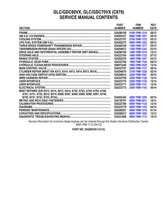
1. GLC/GDC60VX, GLC/GDC70VX (C879)
SERVICE MANUAL CONTENTS
SECTION
PART
NUMBER
YRM
NUMBER
REV
DATE
FRAME............................................................................................................................ 524288189 0100 YRM 1316 08/13
GM 4.3L V-6 ENGINES................................................................................................... 524265337 0600 YRM 1251 05/14
COOLING SYSTEM........................................................................................................ 524223757 0700 YRM 1123 03/13
LPG FUEL SYSTEM (GM 4.3L)...................................................................................... 524262275 0900 YRM 1242 08/12
THREE-SPEED POWERSHIFT TRANSMISSION REPAIR........................................... 524288194 1300 YRM 1317 03/13
TRANSMISSION REPAIR (DANA SPICER) 2X2........................................................... 524294873 1300 YRM 1343 03/14
DRIVE AXLE AND DIFFERENTIAL ASSEMBLY REPAIR (WET BRAKE)................... 524288199 1400 YRM 1318 12/13
STEERING AXLE............................................................................................................ 524223764 1600 YRM 1133 07/13
BRAKE SYSTEM............................................................................................................ 524262279 1800 YRM 1247 03/13
HYDRAULIC GEAR PUMP............................................................................................. 524223766 1900 YRM 1136 04/14
HYDRAULIC CLEANLINESS PROCEDURES............................................................... 550073240 1900 YRM 1620 12/14
MAIN CONTROL VALVE................................................................................................ 524223767 2000 YRM 1137 04/14
CYLINDER REPAIR (MAST S/N A513, A514, A613, A614, B513, B514)..................... 524294878 2100 YRM 1328 02/14
HIGH VOLTAGE SWITCH (HVS) IGNITION.................................................................. 524208014 2200 YRM 1097 05/14
WIRE HARNESS REPAIR.............................................................................................. 524223769 2200 YRM 1128 12/14
USER INTERFACE......................................................................................................... 524223770 2200 YRM 1130 12/14
USER INTERFACE......................................................................................................... 524223771 2200 YRM 1131 12/14
ELECTRICAL SYSTEM.................................................................................................. 524223772 2200 YRM 1142 04/14
MAST REPAIRS (S/N A513, A514, A613, A614, A702, A703, A704, A705, A706,
A707, A751, A752, B513, B514, B586, B587, B588, B589, B590, B591, B749,
B750, B751, B752, B753, B754)................................................................................ 524265342 4000 YRM 1250 02/14
METRIC AND INCH (SAE) FASTENERS....................................................................... 524150797 8000 YRM 0231 10/13
CALIBRATION PROCEDURES...................................................................................... 524223780 8000 YRM 1134 12/14
DIAGRAMS..................................................................................................................... 524223779 8000 YRM 1152 04/14
PERIODIC MAINTENANCE............................................................................................ 524288207 8000 YRM 1319 01/14
CAPACITIES AND SPECIFICATIONS........................................................................... 524288212 8000 YRM 1320 12/12
DIAGNOSTIC TROUBLESHOOTING MANUAL............................................................ 524221866 9000 YRM 1112 12/14
Service information for Cummins diesel engines can be ordered through the Hyster Literature Distribution Center.
9000 YRM 1112 ON CD
PART NO. 524288184 (12/14)
2. 100 YRM 1316 Description
General
WARNING
The lift truck must be put on blocks for some types
of maintenance and repairs. The removal of the
following assemblies will cause large changes in
the center of gravity: mast, drive axle, engine and
transmission, and counterweight. When the lift
truck is put on blocks, put additional blocks in the
following positions to maintain stability:
• Before removing the mast and drive axle, put
blocks under the counterweight so the lift truck
cannot fall backward.
• Before removing the counterweight, put blocks
under the mast assembly so the lift truck cannot
fall forward.
The surface must be solid, even, and level when
the lift truck is put on blocks. Make sure any blocks
used to support the lift truck are solid, one-piece
units. See the procedure How to Put Lift Truck
on Blocks in the Operating Manual or the Periodic
Maintenance section for your lift truck.
If additional engine repairs are necessary for lift trucks
covered in this manual see:
• GM Engines, 4.3 Liter V-6 600 YRM 1251
• Kubota Diesel 3.8L Engines 600 YRM 1557
If additional transmission repairs are necessary for lift
trucks covered in this manual see:
• Powershift Transmission, Repair 1300 YRM 1129
• Powershift Transmission, Repair 1300 YRM 1529
• One and Two Speed Transmissions, Repair 1300
YRM 1569
• Three-Speed Powershift Transmission Repair
1300 YRM 1317
• Two-Speed Powershift Transmission Repair 1300
YRM 1343
This section contains the description of the frame (see
Figure 1) and connected parts. Procedures for remov-
ing and installing the counterweight, hood, overhead
guard, engine and transmission, and exhaust system
are found in this section. Checks for the operator re-
straint system and procedures for the repair of tanks
and installation of safety labels are also included.
Description
The frame is one weldment and includes the hydraulic
tank and fuel tank for gasoline or diesel fuel. See Fig-
ure 1.
There is a counterweight for each capacity of lift truck.
The counterweights are similar in appearance, but are
different weights. See Table 2.
The muffler is fastened to the frame inside the counter-
weight.
The overhead guard, cowl, and hood are installed on
the frame. The hood is connected to the frame with
hinges. Two gas-controlled springs provide assistance
when raising the hood and hold the hood in the open po-
sition. The floor plate and side covers can be removed
for access to the engine, transmission, and other com-
ponents.
1
3. Description 100 YRM 1316
1. COWL PLATE
2. FENDERS
3. HOOD MOUNTS
4. COUNTERWEIGHT MOUNTS
5. HYDRAULIC TANK
6. FUEL TANK (GAS OR DIESEL)
Figure 1. Frame
2
4. 100 YRM 1316 Hood, Seat, Dash, and Side Covers Replacement
Hood, Seat, Dash, and Side Covers Replacement
REMOVE
1. Remove the floor mat and floor plate. See Figure 3.
2. Slide the seat to the closest position to the steering
column.
3. Fully tilt the steering column forward.
4. If your truck is equipped with an LPG tank, swing
the tank off to the side. Push in the bracket re-
lease pin, swing the tank and bracket out to the
side of the lift truck. If your truck is equipped with
a swing-out and drop-down LPG tank bracket (EZ
Tank Bracket), swing the tank down to the side of
the truck for ease of removal. See one of the fol-
lowing Service Manuals for procedures to swing
the LPG tank to the side.
LPG Fuel System, GM 4.3L Engine With GFI 900
YRM 1242 for lift truck models:
• GLC/GDC60VX, GLC/GDC70VX (GC/GLC/
GDC135VX, GC/GLC/GDC155VX) (C879,
D879)
LPG Fuel System, GM 4.3L Engine With PSI 900
YRM 1556 for lift truck models:
• GLC/GDC60VX, GLC/GDC70VX (GC/GLC/
GDC135VX, GC/GLC/GDC155VX) (D879, E879,
F879)
5. Raise the hood latch, unlatch and lift up the hood.
See Figure 2.
6. Remove the two capscrews holding the left and
right rear side panel to the frame. Remove the rear
side panel from the frame. See Figure 3.
3
5. Hood, Seat, Dash, and Side Covers Replacement 100 YRM 1316
NOTE: SWIVEL SEAT AND VENTED HOOD ARE OPTIONAL FEATURES.
A. SIDE VIEW OF HOOD AND SEAT
B. SIDE VIEW OF HOOD
C. BOTTOM VIEW OF HOOD
D. 3-D VIEW OF VENTED HOOD WITH SWIVEL
SEAT
1. SEAT
2. HOOD
3. FRAME
4. SEAT WIRE HARNESS
5. SEAT WIRE HARNESS CONNECTOR
6. CABLE CLIPS
7. HINGE SCREWS
8. GAS SPRING
9. ATTACHMENT HOLES ATTACHING HOOD TO
SEAT (SEMI-SUSPENSION)
10. SEAT WIRE HARNESS BRACKETS
11. SEAT LINER
12. HOOD LATCH
13. ATTACHMENT HOLES ATTACHING HOOD TO
SEAT (NON-SUSPENSION)
14. ATTACHMENT HOLES ATTACHING HOOD TO
SEAT (FULL SUSPENSION)
15. SPACER
16. FLANGE NUTS
Figure 2. Hood and Seat Arrangement
4
6. 100 YRM 1316 Hood, Seat, Dash, and Side Covers Replacement
1. DEBRIS COVER
2. COUNTERWEIGHT COVER
3. RADIATOR COVER
4. LEFT SIDE REAR PANEL (GAS AND DIESEL
SHOWN)
5. RIGHT SIDE REAR PANEL
6. UPPER STEERING
COLUMN COVER
7. LOWER STEERING
COLUMN COVER
8. SEAL
9. FLOOR MAT
10. FLOOR PLATE
11. SPLASH SHIELD
(GAS AND DIESEL)
12. CAPSCREW
13. FOLD OVER NUT
14. SEAL PLATE ASSEMBLY
15. RIGHT SIDE FRONT
FENDER COVER
16. RIGHT SIDE STEP PLATE
17. RIGHT SIDE STEP PLATE
18. DASH ASSEMBLY
19. KICK PANEL
Figure 3. Side Covers, Floor Plate, and Cowl Components
5
7. Hood, Seat, Dash, and Side Covers Replacement 100 YRM 1316
7. Remove the two capscrews holding the left and
right fender covers to the front overhead guard leg.
Remove covers. See Figure 3.
8. Remove the four capscrews holding the left and
right front side panels to the frame. Remove pan-
els.
9. Fully lower the steering column.
10. Remove upper steering column cover by pulling
up on upper steering column cover to release the
latches (one on either side), and pulling cover away
from steering column. See Figure 4.
11. Remove the five fasteners (see Figure 4) securing
the dash to the top of the cowl. Remove the four
clips, located underneath dash, that attach the dash
to the kick panel. Lift to remove the dash.
12. Lift the kick panel to remove it from the truck. See
Figure 3.
13. Remove the three capscrews holding the seal plate.
Remove seal plate. See Figure 5.
14. Disconnect the seat wire harness connector. See
Figure 2.
CAUTION
When removing the seat from the hood, do not use
an impact wrench to remove the capscrews. Dam-
age can be caused to the threads on the screws and
in the holes.
15. If the seat is to be removed, and truck is equipped
with a non-swivel seat, remove the seat wire har-
ness from the seat wire harness brackets that are
attached to the underside of the hood. Remove the
cable clips from the seat wire harness. If truck is
equipped with a swivel seat, remove seat wire har-
ness from seat wire harness bracket attached to the
underside of the hood and behind the seat. See
Figure 2.
16. Remove the four flange nuts holding the seat to the
hood. Lift the seat off the hood. Pull the seat wire
harness through the hood. See Figure 2.
17. Remove the capscrews and washers at the top of
the gas springs. Remove gas springs from the
hood. See Figure 2.
18. Remove the hinge screws, located in the rear of the
hood.
19. Lift the hood from the truck. See Figure 2.
INSTALL
1. Place the hood onto the lift truck frame.
2. Install the hinge screws, located in the rear of the
hood, and tighten to 38 N•m (28 lbf ft). See Fig-
ure 2.
3. Align the holes in the gas springs with holes in the
hood. There are two sets of holes used to install
the gas springs to the hood, based on the type of
seat the installed on the lift truck. One set is for
installing the cylinder end of the gas springs and
the other set is for attaching the rod end of the
gas springs. Install capscrews and washers to at-
tach gas springs to the hood. Refer to Figure 6
and Table 1 for correct holes used to connect the
rod end of the cylinder, depending on the type of
seat installed on the lift truck. Tighten capscrews
to 19.2 N•m (170 lbf in).
6
8. 100 YRM 1316 Hood, Seat, Dash, and Side Covers Replacement
NOTE: TOP VIEW OF DASH SHOWN.
A. INDICATES TO PULL UP TO UNLATCH
1. ALLEN SCREWS
2. COWL
3. UPPER STEERING COLUMN COVER
4. LOWER STEERING COLUMN COVER
Figure 4. Remove Dash From Cowl
7
9. Hood, Seat, Dash, and Side Covers Replacement 100 YRM 1316
1. CAPSCREWS 2. SEAL PLATE
Figure 5. Remove Seal Plate From Dash
8
10. 100 YRM 1316 Hood, Seat, Dash, and Side Covers Replacement
NOTE: SEE TABLE 1 FOR HOLES TO USE TO ATTACH ROD END OF GAS SPRING.
A. LEFT SIDE
B. RIGHT SIDE
C. FULL SUSPENSION SEAT
D. NON-SUSPENSION SEAT
1. MOUNTING LOCATION FOR CYLINDER END OF GAS SPRING FOR NON-SUSPENSION SEAT
2. MOUNTING LOCATION FOR CYLINDER END OF GAS SPRING FOR SEMI OR FULL SUSPENSION SEAT
Figure 6. Gas Spring Installation
9
11. Hood, Seat, Dash, and Side Covers Replacement 100 YRM 1316
Table 1. Gas Spring Installation, Holes for Installing Rod Ends (See Figure 6)
Full or Semi Suspension Seat Non-Suspension Seat
Counterweight
Type
Left Side Right Side Left Side Right Side
Standard
Counterweight
2 2 1 1
4. Install latch striker in highest slot position. Check
that latch striker is in center of jaws of hood latch
when hood closes. Open and close the hood to en-
sure that the center pin strikes the hood latch prop-
erly and that the stop screw contacts the frame. A
properly closed hood MUST click twice on the hood
latch. If the hood latch does not close properly,
loosen the capscrews on the back of the center pin
and adjust the center pin up or down as required for
correct alignment. See Figure 7.
5. Push down until hood just touches rubber bumper.
Make sure latch striker is still in center of hood latch.
Open hood and tighten capscrews for latch.
CAUTION
When installing the seat to the hood, do not use an
impact wrench to install the capscrews. Damage
can be caused to the threads on the screws and in
the holes.
6. Place the seat on the hood and thread the seat wire
harness through the hole in the hood. See Figure 2.
7. Align the holes in the seat with the holes in the
hood. Insert washers and capscrews. Tighten cap-
screws to 18 N•m (159 lbf in).
8. If truck is equipped with a non-swivel seat, tie cable
clips to seat wire harness and insert harness into
seat wire harness brackets under hood. If truck is
equipped with a swivel seat, secure seat harness
to bracket. See Figure 2.
9. Check operation of hood latch. Have an opera-
tor sit in the seat. Make sure hood is fully closed
(two clicks). Also check that hood touches rubber
bumper. If necessary, repeat Step 5.
10. Using three capscrews, Install seal plate. See Fig-
ure 5.
11. Install kick panel onto truck. See Figure 3.
12. Install dash and allen screws to top of cowl. See
Figure 4. Tighten capscrews to 0.5 to 0.6 N•m (5 to
6 lbf in).
13. Install four clips to attach the dash to kick panel.
See Figure 4.
10
12. 100 YRM 1316 Hood, Seat, Dash, and Side Covers Replacement
14. Install upper and lower steering column covers by
connecting the two covers together and pressing
each side until latched.
15. Using four capscrews, install the left and right front
side panels to frame. See Figure 3.
16. Using two capscrews install the left and right fender
covers to front of overhead guard legs.
17. Using two capscrews, install the left and right rear
side covers to frame. See Figure 3.
18. Install the floor mat and floor plate.
19. If truck is equipped with an LPG tank, swing
LPG tank into position on back of counterweight.
See one of the following Service Manuals for
procedures to swing the LPG tank onto the coun-
terweight.
LPG Fuel System, GM 4.3L Engine With GFI 900
YRM 1242 for lift truck models:
• GLC/GDC60VX, GLC/GDC70VX (GC/GLC/
GDC135VX, GC/GLC/GDC155VX) (C879,
D879)
LPG Fuel System, GM 4.3L Engine With PSI 900
YRM 1556 for lift truck models:
• GLC/GDC60VX, GLC/GDC70VX (GC/GLC/
GDC135VX, GC/GLC/GDC155VX) (D879, E879,
F879)
20. Adjust the steering column and seat positions. 1. HOOD
2. HOOD LATCH
3. CENTER PIN
4. CAPSCREW
Figure 7. Hood Latch Adjustment
11
13. Thank you very much for
your reading. Please Click
Here. Then Get COMPLETE
MANUAL. NO WAITING
NOTE:
If there is no response to
click on the link above,
please download the PDF
document first and then
click on it.
14. Steering Column 100 YRM 1316
Steering Column
DESCRIPTION
This section describes the repair procedures for the
steering column. The steering column assembly
mounts to the cowl inside the operator compartment
and is the mechanical connection between the steering
wheel and the steering control unit. The steering col-
umn includes the steering wheel, housing, bracket and
lower shaft. For lift trucks with gas and LPG engines,
bolts and bushings attach the steering column to the
cowl standoffs. For lift trucks with diesel engines, bolts,
bushings and isolators attach the steering column to
the cowl standoffs. See Figure 8.
STEERING COLUMN REPAIR
Remove
1. Put blocks on each side (front and back) of tires to
prevent lift truck from moving.
WARNING
Disconnect the battery before removing any covers
to avoid injury to personnel.
2. Attach a tag on battery connector or negative bat-
tery cable stating, DO NOT CONNECT BATTERY.
Move steering column to most FORWARD position.
CAUTION
If a puller tool is used to remove steering wheel
from steering column, be careful not to damage
horn wires.
NOTE: This procedure is for removal of all components
of steering column assembly. Not all components are
removed for a repair procedure. Do only those steps of
procedure necessary to remove required component.
NOTE: Tag wires prior to disconnect.
3. Remove horn button assembly and disconnect
electrical wires. Remove large hex nut and steer-
ing wheel from steering column. See Figure 9.
4. Remove steering column covers. Remove floor
mats and floor plate. See section Hood, Seat,
Dash, and Side Covers Replacement.
NOTE: Perform Step 5 for lift trucks equipped with gas
or LPG engines.
5. Remove four capscrews, four bushings and steer-
ing column from cowl standoffs. See Figure 10.
NOTE: Perform Step 6 for lift trucks equipped with
diesel engines.
6. Remove four capscrews, four bushings, four isola-
tors, steering column and four isolators from cowl
standoffs. See Figure 10.
Disassemble
NOTE: Remove and discard snap rings if installed.
1. Remove two pins and gas spring from housing.
See Figure 11, for lift trucks manufactured before
January, 2012.
See Figure 12, for lift trucks manufactured after Jan-
uary, 2012.
2. Remove two pivot bolts, two bushings, two nuts and
bracket from housing.
See Figure 11, for lift trucks manufactured before
January, 2012.
See Figure 12, for lift trucks manufactured after Jan-
uary, 2012.
3. Remove split pin and lower shaft from upper shaft.
See Figure 11, for lift trucks manufactured before
January, 2012.
See Figure 12, for lift trucks manufactured after Jan-
uary, 2012.
4. Remove connector from connector bracket. Re-
move connector bracket, fastener, four screws and
two horn contacts from housing.
See Figure 11, for lift trucks manufactured before
January, 2012.
See Figure 12, for lift trucks manufactured after Jan-
uary, 2012.
12