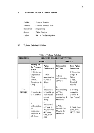
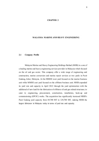
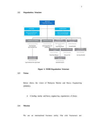
1
CHAPTER 1
INTRODUCTION
1.1 Objectives of the Training
The objectives of the industrial training are:
1. To provide exposure to students about engineering in the
respective fields and type of industries selected.
2. To expose to students a responsibility of becoming an
engineer
3. To build up communication skills in engineering which
include daily interaction with the working environment and technical
writing.
4. To develop and increase the work skills based on the guidance
from professional
5. To gain extra knowledge in various aspects such as mentality,
emotions, physical and social during three months training.
2
1.2 Location and Position of In-Plant Trainee
Position : Practical Students
Division : Offshore Business Unit
Department : Engineering
Section : Piping Section
Project : SK316 Gas Development
1.3 Training Schedule/ Syllabus
Table 1: Training Schedule
DURATION SUBJECTS COVERED/ACTIVITIES
WEEK 1 WEEK 2
1ST
MONTH
Briefing on
the Program
by HR
Piping
Fundamental
Introduction
to Valve
Basic Piping
Connection
1. Briefing on
Organization
Chart,
Section,
Department &
Group
1. Basic
understanding
of pipe &
fittings
1. Basic
understanding
of Valve
1. Connection
of Pipe &
Fittings
(Flange,
Threaded,
Socket)
2. Introduction
to oil and Gas
2.
Introduction
to Metallic &
Non Metallic
pipe &
fittings
2.
Understanding
of Valve
Selection,
Application &
Operation
2. Welding
connection
(Ferrous &
Non Ferrous)
3.
Understanding
the
Engineering
Procedure &
Job Scope
3.
Introduction
to Plastic &
Polymer Pipe
& Fittings-
GRE, FRP,
GRP
3. Valve
internal Part,
Material &
Dimension
3. Plastic joint
(GRE, PVC,
UPVC, ABS)
3
4.
Understanding
the Piping
Hand Book
WEEK 3 WEEK 4
Material
Take off
Purchase
Requisition
Template
SAP System
Material
Tracking
1. Generate
Manual MTO
from P&ID
1. PDMS
Spec &
Catalogue
Check
1. Introduction
to SAP System
1. Monthly
PDMS Global
Tracking
2. Generate
PDMS Global
MTO for
Purchase
Requisition &
Tracking
2. PR
Template for
Pipe, Fitting
& Valve
2. Create, Edit
& Change
Material
2. Updated
Material
Tracking
3. Generate
Manual MTO
from Piping
Plan
3. Document
Required for
MR
3. Raised &
Check the MR
3. Delta
Material for
the month
2nd
MONTH
WEEK 1 WEEK 2
Introduction
to Bidding
TBE &
Vendor Data
Review
Basic Welding Testing
1.
Understanding
of Bidding
Document
1. Valve, Pipe
& Fitting
1. Introduction
to welding
1. Non
Destructive
Test
2. Manual
MTO
2. Spring
Hanger
2. Type of
welding - EFW
& ERW
2. Destructive
Test
3. Technical
requirement &
Deliverable
3. Tag Item
3. Brazing &
Soldering
3. Hydro &
Pneumatic Test
4. Welding
Tools
4. Blasting &
Painting
4
WEEK 3 WEEK 4
ASME B31.3
Code &
Standard
Basic
understanding
of Piping
Drawing
Basic
understanding
of Piping
Drawing
1. Introduction
and
fundamental
of ASME
B31.3 Process
Piping.
1. ASME ,
API & ISO
1. P&ID &
Piping
Specification
1. Pipe Support
drawing
2. ASTM,
AISI
1. Isometric
DWG
2. Pipe Support
Standard
3. MSS - SP,
BS, JIS, DIN
2. Isometric
drawing mark-
up
3.Welding
Symbol
4. Project
Spec &
Requirement
3. Isometric
Drawing
Checking
4. Pipe Span
5.Client
Specification
3rd
MONTH
WEEK 1 WEEK 2
Introduction
to IDC &
VDI
1. Mechanical
IDC & VDI
2. Instrument /
Electrical IDC
& VDI
3. Structure /
Architecture
IDC & VDI
WEEK 3 WEEK 4
Weight
Control
Report
(WCR)
Assessment /
Review
5
1. Providing
piping weight
and Center of
Gravity
(COG).
1. Presentation
6
CHAPTER 2
MALAYSIA MARINE AND HEAVY ENGINEERING
2.1 Company Profile
Malaysia Marine and Heavy Engineering Holdings Berhad (MHB) is a one of
a leading marine and heavy engineering services provider in Malaysia which focused
on the oil and gas sector. This company offer a wide range of engineering and
construction, marine conversion and marine repair services at two yards in Pasir
Gudang, Johor, Malaysia. At the MMHE west yard focused on the marine business
unit while MMHE east yard focused on the offshore business unit. MHB expanded
its yard size and capacity in April 2012 through the yard optimization with the
additional of new land for the fabrication of offshore oil and gas related structures; to
cater to engineering, procurement, construction, installation, hook-up and
commissioning (EPCIC) works. The acquisition has significantly increased MHB’s
Pasir Gudang yard capacity from 69,700 MT to 129,700 MT, making MHB the
largest fabricator in Malaysia today in terms of yard size and capacity.
7
2.2 Organization Structure
2.3 Vision
Below shows the vision of Malaysia Marine and Heavy Engineering
(MMHE):
 A leading marine and heavy engineering organization of choice.
2.4 Mission
We are an international business entity. Our core businesses are:
Figure 1: MHB Organization Structure
8
 Offshore construction
 Offshore conversion
 Marine repair
1) We provide quality products at a competitive price.
2) We conduct all our activities in a manner that safeguards health,
safety and the environment.
3) Our employees are our greatest asset and we uphold our shared
values in everything we do.
2.5 Offshore Business Unit (OBU)
MHB offers a full range of construction and engineering services for the
offshore and onshore oil and gas industry, from detailed engineering design and
procurement to construction, installation, hook-up and commissioning (EPCIC). Our
completed and ongoing projects include the construction of oil and gas platforms,
jackets, topsides, process modules, turrets, semi-submersibles, floating production
systems, mooring buoy systems, mobile offshore storage units, living quarters and
substructures.
Offshore Construction services
 Deep water facilities
 Integrated platforms
 Wellhead platforms
 Compression, dehydration, water injection modules
 Jackets
 Living quarters
9
 Turret and mooring buoy
Onshore Construction services
 Process skids and modules, furnaces and fire heaters
 Manufacturer of steel tubular and piles
 Process equipment (air fin coolers, heat exchangers, process column
& towers and pressure vessels
2.6 Project SK316
PETRONAS CariGali Sdn. Bhd. has undertaken the development of the NC3
gas fields located in SK316 Block, approximately 200km North of Bintulu, Sarawak.
The water depth in NC3fields is around 104m-107m. The development of NC3 fields
is envisaged to be in complex-type configuration. NC3 will be made the hub for the
SK316 gas development which includes future NC8 Wellhead platform. NC3
Complex comprise of a Central Processing Platform (CPP) with Living Quarters and
a bridge-linked Drilling Platform. Subsea Pipeline connects NC3 Drilling Platform to
Existing Riser Platform E11R-C.
The processed gas will be evacuated to shore via the existing trunk line
through E11R-C or dedicated newly-to-be-installed trunk line to shore. The
dehydrated condensate will be spiked into the same trunk line. The processed gas
and dehydrated condensate will be separated again onshore prior to be fed into a new
LNG Plant's Train 9. The gross volume of the processed gas is 660MMSCFD
including 20% CO2.
10
Figure 2: Location of the Platform
11
Figure 3: Model of the Platform
12
CHAPTER 3
PIPING SECTION
3.1 Piping Procedure
Piping procedure provides a complete rules and practices in piping section.
3.1.1 Drawing Register
Drawing register is to control all in and out of drawings for every new
revision. After company has got the project tender, client will pass the approval for
construction (AFC) drawing and proceed to the issue for construction (IFC) drawing.
Drafters are responsible to check drawing no. and revision no. during key-in
the drawing register. If drafters found any errors, such as double issuance, wrong
revisions or sheet no. does not tally with the previous issuance, drafters have to liaise
with designers or engineers and highlight the discrepancies that have been spotted.
Inform the lead engineer if necessary.
13
3.1.2 Site Technical Query (STQ)
Site technical query is needed to be issue when the engineer found any
inconsistency exist in the drawing which against with the specifications, codes and
standards and project requirements. Other than that, if the engineer proposed some
substitutions on the projects, he also needed to issue STQ to the client. When obtain
the approval, the drawing will revise and send back to IFC.
3.1.3 Material Take Off (MTO)
Material take off is divided into three which are global MTO, details MTO
and manual MTO. Global MTO is summary of output data from Plant Design
Management System (PDMS) software, which contains all material details for every
project. The main functions of these data are for monitoring and purchasing material
based on design that had been model. Global MTO shall be generated from PDMS
software by PDMS Administrator and submit to lead Piping Engineer.
Detail MTO is output data from Plant Design Management System (PDMS).
Details MTO consist of details materials per item, and can be used as reference to
track the material location (by having pipe name for each item), meanwhile Global
only can provide the summary or overall quantity of material apply in the project.
Manual MTO can be categorize as out source material required not via
PDMS, this kind of MTO is use due to certain condition where the material required
early delivery, some of them is due to any missing or misplaced during fabrication
stage
14
3.1.4 Material Requisition
Material requisition is the requesting for the material that needed to be
purchase.
3.1.5 Technical Bid Evaluation (TBE)
Objective of the technical bid evaluation is to evaluate the vendor’s proposal
and to get the potential vendors which comply with the specifications and project
requirements.
3.1.6 Inter-Discipline Check (IDC)
Inter-discipline check is the checking between other discipline the existing
data and document to avoid conflicts and discrepancies. Other than that, to make sure
all items meeting the criteria, standards and project requirements. Any discrepancy
from that document should be highlighted to client true STQ after discussion have
been made with other section.
3.1.7 Vendor Data Incorporation (VDI)
Vendor data incorporation is the process where checking the 3D-model is
tally with the item and equipment supply by the vendor.
15
3.1.8 Vendor Data Review (VDR)
Successful bidder will provides drawings for item that needed to be
purchase. Engineer’s task is to study and check the detail of drawings and compare
with specifications. If have any comments, the drawings will send back to the vendor
for a corrections. The final approved drawings must be complying with all the
requirements needed in the project.
3.2 Code and Standard
In piping field, code and standard is important to be expert since we use it as
a guideline or to give strong justifications to the client when we faced some problem
or to proposed a substitution of material on their project. There are a lot of codes and
standard has been used but these three ASME. ASTM and MSS are the most
popular.
1.American Society for Mechanical Society (ASME)
a) ASME has developed several codes and standard to enhance
public safety and productivity of Engineering.
b) ASME standard on the sort of technical guide for the
engineer regarding the usage of product
c) It set the guideline for engineer to follow the common
manufacturing all over the workl
16
ASME B31.3
a) For the process piping, we use standard code ASME B31.3
which is typically found in the petroleum refinery, chemical
plant, pharmaceutical, textile and gas processing plant.
b) In order to do process piping design, ASME B31.3 provides
background information, their previous historical and expert
commentary on the requirements for process piping design
to us use as a guidelines.
c) ASME B31.3 does not tell us to follow exactly the
procedure, but use the standard as a guideline.
2.American Society for Testing and Materials (ASTM)
These standards are used and accepted worldwide and cover the area
such as metals, plastics, petroleum and others. It provides a
3.Manufactures Standardization Society (MSS)
To provide guidelines to develop engineering standard practices for the
use and benefit of the industry and users of its products.
3.3 Piping Components
There are a lot of piping components used such as pipe, branch connections,
flanges and gasket. All the component selection is based on the piping component
standard. Some of the piping standards are:
17
Table 2: Piping Component Standard
B16.1 – Cast Iron Pipe Flanges
B16.3 – Malleable Iron Threaded Fittings
B16.5 – Pipe Flanges and Flanged Fittings
B16.9 – Wrought Steel Butt-weld Fittings
B16.11 – Forged Fittings, Socket Welding & Threaded
B16.20 – Metallic Gaskets
B16.22 – Wrought Copper Solder Joint Fittings
B16.34 – Valves Flanged, Threaded and Welded
3.3.1 Pipe
The term pipe can be identified by its nominal pipe size (NPS) with wall
thickness defined by schedule number (SCH). The nominal pipe size is a North
American which is set of standard sizes for pipe used for high and low pressure or
temperatures.
For a given NPS, the outside diameter stays constant and the wall thickness
increases with larger schedule number. The inside diameter will depend upon the
pipe wall thickness specified by the schedule number. There are three types of end of
the pipe which are plain end (PE), threaded end (TE) and beveled end (BE).
Figure 4: Types End of the Pipe
18
The PE pipes will be used for small diameter and in the combination with slip
on flanges and socket weld fittings. While for the TE pipes, it is practically used for
small diameters and the connection will be made with threaded flanges and threaded
fittings. For the BE pipes is applied to all diameters butt-weld flanges or fittings and
directly welded to each other or to the pipe.
3.3.2 Fittings
A pipe fittings can be defined as a part of piping system which is use when
involve changing diameter of pipe, changing direction or branching. Fittings divided
into three groups which are butt-weld, socket weld and threaded.
1. Butt-weld fittings
Butt-weld fittings are defined in the ASME B16.9 standards.
2. Socket Weld Fittings
Socket Weld fittings are mainly used for small pipe diameters generally
for piping whose nominal diameter is NPS 2 or smaller. Socket-welded joints
construction is a good choice wherever the benefits of high leakage integrity and
great structural strength are important design considerations. They are available
in three pressure ratings: Class 3000, 6000 and 9000 which defined in the ASME
B16.11 standards
ASME B31.1 says that:
In assembly of the joint before welding, the pipe or tube shall be inserted into
the socket to the maximum depth and then withdrawn approximately
19
1/16" (1.6 mm) away from contact between the end of the pipe and the shoulder
of the socket.
3. Threaded Fittings
Threaded fittings are typically used for small bore piping generally
nominal diameter is NPS 2 or lower. Threaded is a screwed fitting for class 2000,
3000, and 6000 are defined in the ASME B16.11 standards.
3.3.3 Flanges
A flange is used as a method of connecting pipes with other piping system
equipment such as valves and pumps. Joints of the flanges are bolting together by
two flanges with a gasket between them to provide a sea and flanges also provide
easy access for cleaning and modification. The most type of flanges used on
chemical industry are welding neck flange, slip on flange, socket weld flange, lap
joint flange, threaded flange and blind flange.
Figure 5: Types of the Flanges
20
Different types of flange faces are used as the contact to seat the sealing
gasket material. The types are raised face (RF), flat face (FF) and ring type joints
(RTJ).
1. Raised Face (RF)
Figure 6: Raised Face Flanges
Most common use, easy to identify and known as raised face because gasket
surfaces are raised above the bolting circle face. The purpose of a RF flange is to
concentrate more pressure on a smaller gasket area and thereby increase the
pressure containment capability of the joint. It is has been use for pressure rating
150 until 600.
2. Flat Face (FF)
Figure 7: Flat Face Flange
The flat face flange is never to be bolted to a raised face flange. ASME B31.1
says that:
21
“When connecting flat face cast iron flanges to carbon steel flanges, the
raised face on the carbon steel flange must be removed, and that a full face
gasket is required”. This is to keep the thin, brittle cast iron flange from being
sprung into the gap caused by the raised face of the carbon steel flange.
3. Ring Type Joint (RTJ)
Figure 8: Ring Type Joint Flange
Ring type joint flanges usually used for high pressure or rating which is class
600 and above. This flanges seal when tightened bolts compress the gasket between
the flanges into the grooves, deforming the gasket to make contact inside the
grooves, creating a metal to metal seal. The flange that seal with gasket, the raised
faces of the connected and tightened flanges may contact each other.
3.3.4 Gasket
Gaskets are used to provide static seal between two flanges faces at various
operating conditions with varied pressure and temperature ratings. There are three
types of gasket which are metallic, semi-metallic and non-metallic. Metallic ring-
joint gasket materials are covered by ASME B16.20, ring join gasket and grooves for
steel pipe flanges. Non-metallic gasket is covered in ASME B16.21, Non-metallic
gasket for pipe flanges.
22
Figure 9: Non-Metallic Gasket
1. Non-Metallic gaskets are usually composite sheet materials are used with
flat-face and raised-face flanges in low Pressure Class applications. ASME
B16.21 covers types, sizes, materials, dimensions, dimensional tolerances,
and markings for non-metallic flat gaskets.
2. Semi-Metallic gaskets are composites of metal for strength and a non-
metallic material provides conformability. Often used semi-metallic gaskets
are spiral wound, camprofile and a variety of metal-reinforced graphite
gaskets. ASME B16.20 covers materials, dimensions, dimensional tolerances,
and markings for metallic and semi-metallic gaskets.
23
Figure 10: Spiral Wound Gasket
3. Metallic gasket is used for ring type joint flanges. It is designed to seal
pressures of up to 6,250 psi in accordance with ASME B16.20 and up to
5,000 psi in accordance with API 6A pressure ratings.
3.4 Type and Selection of Valve
3.4.1 Gate Valve
24
Figure 11: Gate Valve
Gate valve is designed to start or stop the flow of fluid. It is consist of three
main parts which are body, bonnet and trim. The body is connected to other
equipment either flanged, screwed or welded connections while the bonnet is
attached to the body by bolts which is easier to do the maintenance. The valve trim
consists of the stem, gate, disc and seat rings.
The stem of the gate valve connected to the hand wheel and disk. It is
responsible to ensure the proper position of the disk. Provide movements to the disk
for opening and closing of the valve. There are two types of stem which are rising
stem and non-rising stem. For the rising stem type, the stem will rise above the
handwheel if the valve is opened. While for the non-rising stem, there is no upward
movement if the valve is opened. The stem will thread into the disk and when the
handwheel is rotated, the stem will remain vertically stationary.
The disadvantage of this valve is the gate valve is not suitable for regulate or
throttle the flow.
25
3.4.2 Globe Valve
Globe valve is designed to stop, start and regulate the flow. There are three
body designs for the globe valve which are tee pattern, angle pattern and wye
pattern.
Figure 12: Tee Pattern Design of the Globe Valve
1. Tee pattern design is the most common type due to this design experience lowest
coefficient of flow and higher pressure drop. They are used in throttling service
such as bypass process.
Figure 13: Angle Pattern Design of the Globe Valve
2. Angle pattern design is the modification of the tee pattern design of the globe
valve. This end of this design is at angle of 90O.and fluid will be flow at 90
degrees. They also have a slightly lower coefficient of flow than tee pattern
design.
26
Figure 14: Wye Pattern of the Globe Valve
3. Wye-pattern is an alternative for the high pressure process and least flow
resistance.
3.4.3 Check Valve
Function of check valve is to prevent backflow of fluid. It is only works with flow
from one direction. There are two types of check valve which are swing check valve
and lift check valve.
Figure 15: Swing Check Valve
The disk swing away from the seat to allow flow in the forward direction and
return to the valve-seat when flow is stopped to prevent backflow. In order to prevent
the backflow, turbulence and pressure drop in the valve are very low.
27
Figure 16: Lift Check Valve
For the lift check valve, it is suitable for high pressure service where the
velocity of flow is high. As the flow enter, the ball is raised from the seat by the
pressure and when the flow is stop, the ball is forced onto the seat of the valve to
prevent backflow.
3.4.4 Butterfly Valve
Butterfly valve is designed for handling large of flow of liquids, slurry of
liquid with large amount of suspended solid. It can classify into two types which are
wafer type and lugged type.
28
Figure 17: Wafer and Lugged Style Body
A commonly used design is the wafer type that fits between two flanges
while the lugged type design is held place between two flanges by bolt that joins the
two flanges and pass through hole in the valve.
The disks will rotate on either vertical or horizontal axis. The valve will fully
open when the disk lies parallel to the piping run while when the disk approach
perpendicular position, the valve will shut.
3.4.5 Ball Valve
The ball valve is classified into two which are top entry ball valve and split
body ball valve. The top entry ball valve will allow access to valve internals for
maintenance by removal of the valve bonnet-cover. While the split body ball valve
consists of two parts where one part is smaller than another. The ball will inserted at
the larger part and the smaller part is assembled by a bolted connection. Ball valve
consists of two types which are triunion and floating ball valve. Triunion ball valve
is hold by two anchors while floating ball valve does not hold by anchor.
29
The disadvantage of this valve is slurry or suspended particle can settle and
trapped in the body causing leakage or valve failure. While the advantage of this
valve is quick quarter turn on-off operation which is mostly used and savely cost.
3.4.6 Plug Valve
Practically same as the ball valve
3.5 Fabrication drawing
Every drawing have the compulsory item needed to be shown. So mark-up
process is needed to check the drawing either tally with the given by client. The
entire mistake is needed to be correct before issue the drawing. There are four types
of fabrication drawing which are piping and instrumentation drawing (P&ID),
isometric drawing, pipe support drawing and general arrangement drawing (GA).
3.5.1 Piping & Instrumentation Drawing (P&ID)
Piping and instrumentation drawing showing the schematic diagram of the
interconnection between piping and other equipment such as mechanical and
instruments. Shown in P&ID:
1. Flow
2. Line No.
3. Valve and Instrument Tag
30
4. Equipment
5. Piping Class
6. Pipe Size
7. Piping System
8. Process Data
9. Vent and Drain
10. Legend
11. Process Note
12. Vendor Package
13. History Date
14. Reference Drawing
15. Drawing No.
3.5.2 Isometric Drawing
Isometrics drawing allow the pipe to be drawn in a manner by which the
length, width and depth are shown in a single view. In every isometric drawing
should have:
1. Flow arrow
31
2. Dimension
3. Elevation
4. Dock penetration
5. Material description
6. Item no.
7. Weld no.
8. Spool no.
9. Reference line/ P&ID/ GA
10. Design/ Temperature and Pressure Operation
11. Painting and Coating
12. Hydro Test Pressure
13. Reference Drawing
14. Drawing Revision
15. Non Destructive Test
16. Heat Treatment
17. Stress Category
18. Note
32
19. Key Plan
20. North Arrow
21. Description/ Date/ Sign/ Line No.
22. ISO No./ Drawing No.
3.5.3 Pipe Support Location Drawing
Pipe support location drawing will showing location of pipe support and pipe
support no. in plan view. The details shown in pipe support location are:
1. Pipe Routing
2. Pipe Support Location
3. No. of pipe support
4. Dimension with scale
5. Key Plan & North Reference
6. Equipment Rotation & Equipment No.
7. Structure
8. Row & Column Reference
9. Deck Name & Elevation Note
33
10. Note
11. Reference Drawing
12. Revision Drawing & Description Column
13. History Date
14. Project Title, Fabricator Logo, Client Logo, Consultant Logo, Contract
No, Sheet No.
15. Drawing Limits
16. Continue Drawing No.
17. Line No.
18. Instrument Items
3.5.4 General Arrangement Drawing (GA)
A general arrangement drawing is a drawing which showing piping plan or
piping view with complete dimension and scale. In this drawing should show:
1. Pipe Routing
2. Instrumentation Rotation & Instrument No.
3. Line No.
4. Elevation
34
5. Key Plan & North Reference
6. Equipment Rotation & Equipment No.
7. Structure
8. Dimension with Scale
9. Row & Column Reference
10. Deck Name & Elevation
11. Note
12. Reference Drawing
13. Revision Drawing & Description Column
14. History Date
15. Project Title, Fabricator Logo, Client Logo, Consultant Logo.
16. Drawing Limits
3.5.5 Mark-up Process
Process checking the drawing to ensure data, item and location as given by
client and consultant is tally. Identify the wrong item and standard used in the
isometric drawing which required correction before issue the drawing.
35
Standard Color Coding For Checking Drawing:
1. Highlight Yellow: First Checked (incorporated)
2. Highlight Orange: Second Check
3. Highlight Blue: Delete and Remove
4. Highlight Green: Drafting Work
5. Red Pen: Comments, Changes, Correction to be incorporated
6. Blue Pen: For Remarks, instruction and information
3.6 Testing
Testing is performed to ensure there are no unacceptable leaks in the piping
system.
3.6.1 Non-destructive Test
Non-destructive testing will use the application of physical principles from
the detection of flaws or discontinuities in materials. In the field of welding, there are
four non-destructive test are widely used which are ultrasonic testing, dye penetrant
testing, radiographic testing and magnetic particle testing.
1. Ultrasonic non-destructive testing is one of the methods of detecting
the thickness of a test piece through the use of high frequency sound waves.
This method of testing typically used on metals, plastics, composites and
36
ceramics but not suitable used on wood and paper products. High frequency
sound will travel through medium until they encounter a boundary with
another medium such as an air and reflect back to their sources. By doing
these reflections, thickness is measured and evidence of cracks can be found.
2. Dye Penetrant Inspection used to detect any surface-connected
discontinuities such as cracks from fatigue, quenching, and grinding, as well
as fractures, porosity, incomplete fusion, and flaws in joints. It used fluid
which penetrates into clean and dry surfaces breaking discontinuities. Dye
penetrant inspection used to defects in magnesium, aluminum, stainless steel
weld part when magnetic particle examination cannot be used.
Figure 18: Dye Penetrant Inspection
3. Radiographic testing is a non-destructive testing method which uses
invisible X-ray or gamma or short wavelength radiations. The disadvantages
of this method are slow and it is one of the expensive methods. Amount of
energy absorbed by material depend on its thickness and density. On the
other hand, energy not absorbed by the material which cause exposure of the
radiographic film. This area will be dark when film is developed.
37
3.6.2 Hydro and Pneumatic Test
1. Hydrostatic test is when filling the piping system with liquid,
pressurizing and checking for leaks. Test liquid shall be water unless there
are adverse effects or other liquid which is non-toxic. Hydrostatic test is
required except if the owner may choose a pneumatic test if they consider the
hydrostatic test is impractical. The most important reason for this is the
hydrostatic test is more safe compared to pneumatic testing.
Water is a much safer fluid test medium than air because it is nearly
incompressible. Therefore, the amount of work required to compress water to
a given pressure in a piping system is substantially less than the work
required to compress air, or any other gas, to the same pressure
Test pressure: P = 1.5 X Design Pressure
2. Pneumatic test is when pressurizing the piping system with gas and
checking for leaks. Pneumatic pressure testing of piping is at moderate to
high test pressure or at low test pressure with high volume is more hazardous
than hydrostatic pressure testing. It is because the compressed gas will
produce bigger energy. The fluid normally used for a pneumatic test is
compressed air or nitrogen. Nitrogen should not be used in a closed area if
the possibility exists that the escaping nitrogen could displace the air in the
confined space.
Test pressure: P = 1.1 X Design Pressure
38
3.7 Corrosion
In general corrosion is meant by degradation of the materials due to the
interactions with the environment and corrosion of most metals is inevitable. There
are much types of corrosion such as galvanic corrosion, atmospheric corrosion,
corrosion under insulation, crevice corrosion, and stress corrosion cracking chloride.
Table 3: Types of Corrosions
Type Material
affected
Critical factors Prevention
Galvanic
corrosion
All metals
except of noble
metals
One metal corrode when
in electrical contact with
different type of metal and
both immersed in
electrolyte
1. Prevention
through good
design
2. Coated
Atmosphere
corrosion
Carbon and
alloy are most
affected
1. Marine environment
can be very corrosive
as industrial
environment that
contain acids or
sulfur compound that
can form acids.
2. Corrosion rate
increases with the
increases of
temperature
1. Avoid design that
trap water or
moisture
2. Surface
preparation and
proper coating
39
Corrosion
under
insulation
1. Carbon and
low alloy
affected
2. Austenitic
stainless
steel are
affected
1. Poor insulations that
allow water to
become trapped.
2. Corrosion rate
increase with the
increases metal
temperature up to
point where water
evaporate quickly.
3. Insulating materials
that hold moisture are
more of a problem.
1. Maintain the
insulation sealing
to prevent
moisture.
2. Use appropriate
coatings
3. Select coating
which hold less
water.
4. Using low
chloride
insulation.
Crevice
corrosion
1. Carbon and
alloy steels
are affected
2. Austenitic
stainless
steel are
affected
1. Aggressive ions like
chlorides may be
present in the
electrolyte.
2. Corrosion rate
increase with
increasing metal
temperature
Avoid crevices
whenever possible
Chloride
Stress
corrosion
cracking
1. Stainless
steel. Are
highly
susceptible.
2. Duplex
stainless
steel is
mostly
resistant.
1. Increasing
temperature will
increase the
probability of the
cracking.
2. Increasing the levels
of chloride will
increase the live hood
of cracking.
1. When hydro test,
use low chloride
content water and
dry out.
2. Proper coating
during
insulations.
3. Avoid stagnant
design where
chloride can
concentrate.
40
Hydrogen-
Induced
Cracking
1. Carbon and
low alloy
steels are
affected.
2. High alloy
steels are
not
affected.
1. All of these damage
mechanisms are
related to the
absorption and
permeation of
hydrogen in steels.
1. Coating the
surface of the
steel which can
prevent from
damage
2. Changes the pH
of water phase or
cyanide
concentration can
help to reduce
damage.
41
CHAPTER 4
ASSIGNMENTS/ ACTIVITIES
4.1 Material Take Off (MTO)
Material take off is a manually taking the material involved in the
piping and instrumentation drawing (P&ID) which is used for purchasing process.
As a beginner, material take off is one of the procedure that needs to be expert. Since
my supervisor take part in the wellhead platform hence I am done with the material
take off from the P&ID of that platform. Wellhead platform can be described as a
drilling platform. For example in one pipe line, I am take off the material such as
valve, flange and gasket by followed their respective piping class and put all the data
related at the MTO template such as the standard used, rating for the material,
schedule, material grade, size of the component and P&ID number. Form the P&ID
number listed, we can easily identify the location of the component that needed to be
installed. Then, the MTO will be used for material purchase.
During undergo the material take off, there are several problem raised
which are:
1. Problem : Meets two different piping class in one pipeline which have
different rating
42
Solution : Choose the piping class which has the higher rating make
material selection
2. Problem : Meets two different piping class with different material in
one pipeline but both have same rating
Solution : Installed the insulation gasket at the respective location
43
4.2 Vendor Data Review
The basic purpose of Vendor Data Review (VDR) is to ensure all the
technical details in the drawing provided by the vendors are according to the
specification, requirement and data sheet before it had fabricated by the
manufacturer. As a piping engineer, the task is needed to study the drawing given by
vendor and compare with specifications. Engineer’s task is to review the drawings
and data sheet to find errors, mistakes or incompliance of the item to the one who
actually need to be purchased. If have any comments, the drawing will send back to
the vendor for corrections.
44
My supervisor, En Syafiq Jamil told me to do the vendor data review on the
product supply by the Macrospec Sdn. Bhd. I am supposed to check the detail of
drawing on the double block and bleed valve (DBB) and compare with specifications
and dimensions. Based on the checking, there are a lot of missing data such as the
design temperature, pressure test, painting and coating data and has some part of the
valve used the wrong material. Hence the drawing is not approved, needed to be
corrected and resubmit for approval.
4.3 Mark-up Drawing
Mark-up drawing is one of the process checking the given drawing to ensure
the data, item and location as per given by consultant and client. We identify the
wrong item and standard used in the isometric drawing which required correction
before issue the drawing. As a trainee, I am asked by one of the designer engineer at
my department to help him to mark-up the isometric drawing.
During the mark up, I am learnt on how to decide where and what types of FW
are needed to put in the pipe spool. The standard sizes of pipe spool are 6m or 12m.
Term FW is referred to weld with no excess length, FW1 referred to weld with the
excess of 150mm and FFW is referred to weld with the excess of 300mm. Pipe
spools are fabricated from a number of main pipe and pipe fittings such as elbow,
flanges, tees and etc. Raw pipes are cut into required sizes and move with pipe
fittings where some components are fitted together.
45
Figure 19: Pipe Spools
The making of the pipe spool has a benefit but at the same time biggest
drawback is that the spools will not fit on the site and this is the reason why the extra
length of pipe is decided to be done. This is due to several causes but often it is a
misinterpreted isometric by the person in charge or incorrect dimensions on
isometric drawing.
46
CHAPTER 5
CONCLUSION
In general, the main objective of industrial training is to expose to students
the working environment in industry. Being a part of industrial trainee will help
students to have a better understanding because instead of gain a theory concept,
they will practically do the work in industry. The duration of three months period
not enough for student to learn almost everything in the project development and
other important departments. This training gives an opportunity to the students to
experience the situation in the real work industry. Thus, student will be able to
prepare themselves when they have face some problems regarding their work in
industry. Other than that, industrial training also thought how to deal with the staff
and most important with the client. It is because clients are the most important
subject in my project. Lastly, thank you to my company because gives an
opportunity to me to undergo industrial training.
47
REFERENCES
Muhammad Syafiq Bin Jamil
Industrial Supervisor
Piping Engineer
Malaysia Marine and Heavy Engineering,
PLO 3, Jalan Pekeliling, P.O. Box 77,
81700 Pasir Gudang, Johor, Malaysia
012-7424498
48
APPENDIX A
Piping and Instrumentation Drawing (P&ID) of wellhead platform in the
SK316 development project
49
APPENDIX B
Material Take Off template of the wellhead platform in the SK316 development
project
50
APPENDIX C
Piping Standard Details of SK316 Development Project

INDUSTRIAL TRAINING REPORT

  • 1.
    1 CHAPTER 1 INTRODUCTION 1.1 Objectivesof the Training The objectives of the industrial training are: 1. To provide exposure to students about engineering in the respective fields and type of industries selected. 2. To expose to students a responsibility of becoming an engineer 3. To build up communication skills in engineering which include daily interaction with the working environment and technical writing. 4. To develop and increase the work skills based on the guidance from professional 5. To gain extra knowledge in various aspects such as mentality, emotions, physical and social during three months training.
  • 2.
    2 1.2 Location andPosition of In-Plant Trainee Position : Practical Students Division : Offshore Business Unit Department : Engineering Section : Piping Section Project : SK316 Gas Development 1.3 Training Schedule/ Syllabus Table 1: Training Schedule DURATION SUBJECTS COVERED/ACTIVITIES WEEK 1 WEEK 2 1ST MONTH Briefing on the Program by HR Piping Fundamental Introduction to Valve Basic Piping Connection 1. Briefing on Organization Chart, Section, Department & Group 1. Basic understanding of pipe & fittings 1. Basic understanding of Valve 1. Connection of Pipe & Fittings (Flange, Threaded, Socket) 2. Introduction to oil and Gas 2. Introduction to Metallic & Non Metallic pipe & fittings 2. Understanding of Valve Selection, Application & Operation 2. Welding connection (Ferrous & Non Ferrous) 3. Understanding the Engineering Procedure & Job Scope 3. Introduction to Plastic & Polymer Pipe & Fittings- GRE, FRP, GRP 3. Valve internal Part, Material & Dimension 3. Plastic joint (GRE, PVC, UPVC, ABS)
  • 3.
    3 4. Understanding the Piping Hand Book WEEK3 WEEK 4 Material Take off Purchase Requisition Template SAP System Material Tracking 1. Generate Manual MTO from P&ID 1. PDMS Spec & Catalogue Check 1. Introduction to SAP System 1. Monthly PDMS Global Tracking 2. Generate PDMS Global MTO for Purchase Requisition & Tracking 2. PR Template for Pipe, Fitting & Valve 2. Create, Edit & Change Material 2. Updated Material Tracking 3. Generate Manual MTO from Piping Plan 3. Document Required for MR 3. Raised & Check the MR 3. Delta Material for the month 2nd MONTH WEEK 1 WEEK 2 Introduction to Bidding TBE & Vendor Data Review Basic Welding Testing 1. Understanding of Bidding Document 1. Valve, Pipe & Fitting 1. Introduction to welding 1. Non Destructive Test 2. Manual MTO 2. Spring Hanger 2. Type of welding - EFW & ERW 2. Destructive Test 3. Technical requirement & Deliverable 3. Tag Item 3. Brazing & Soldering 3. Hydro & Pneumatic Test 4. Welding Tools 4. Blasting & Painting
  • 4.
    4 WEEK 3 WEEK4 ASME B31.3 Code & Standard Basic understanding of Piping Drawing Basic understanding of Piping Drawing 1. Introduction and fundamental of ASME B31.3 Process Piping. 1. ASME , API & ISO 1. P&ID & Piping Specification 1. Pipe Support drawing 2. ASTM, AISI 1. Isometric DWG 2. Pipe Support Standard 3. MSS - SP, BS, JIS, DIN 2. Isometric drawing mark- up 3.Welding Symbol 4. Project Spec & Requirement 3. Isometric Drawing Checking 4. Pipe Span 5.Client Specification 3rd MONTH WEEK 1 WEEK 2 Introduction to IDC & VDI 1. Mechanical IDC & VDI 2. Instrument / Electrical IDC & VDI 3. Structure / Architecture IDC & VDI WEEK 3 WEEK 4 Weight Control Report (WCR) Assessment / Review
  • 5.
    5 1. Providing piping weight andCenter of Gravity (COG). 1. Presentation
  • 6.
    6 CHAPTER 2 MALAYSIA MARINEAND HEAVY ENGINEERING 2.1 Company Profile Malaysia Marine and Heavy Engineering Holdings Berhad (MHB) is a one of a leading marine and heavy engineering services provider in Malaysia which focused on the oil and gas sector. This company offer a wide range of engineering and construction, marine conversion and marine repair services at two yards in Pasir Gudang, Johor, Malaysia. At the MMHE west yard focused on the marine business unit while MMHE east yard focused on the offshore business unit. MHB expanded its yard size and capacity in April 2012 through the yard optimization with the additional of new land for the fabrication of offshore oil and gas related structures; to cater to engineering, procurement, construction, installation, hook-up and commissioning (EPCIC) works. The acquisition has significantly increased MHB’s Pasir Gudang yard capacity from 69,700 MT to 129,700 MT, making MHB the largest fabricator in Malaysia today in terms of yard size and capacity.
  • 7.
    7 2.2 Organization Structure 2.3Vision Below shows the vision of Malaysia Marine and Heavy Engineering (MMHE):  A leading marine and heavy engineering organization of choice. 2.4 Mission We are an international business entity. Our core businesses are: Figure 1: MHB Organization Structure
  • 8.
    8  Offshore construction Offshore conversion  Marine repair 1) We provide quality products at a competitive price. 2) We conduct all our activities in a manner that safeguards health, safety and the environment. 3) Our employees are our greatest asset and we uphold our shared values in everything we do. 2.5 Offshore Business Unit (OBU) MHB offers a full range of construction and engineering services for the offshore and onshore oil and gas industry, from detailed engineering design and procurement to construction, installation, hook-up and commissioning (EPCIC). Our completed and ongoing projects include the construction of oil and gas platforms, jackets, topsides, process modules, turrets, semi-submersibles, floating production systems, mooring buoy systems, mobile offshore storage units, living quarters and substructures. Offshore Construction services  Deep water facilities  Integrated platforms  Wellhead platforms  Compression, dehydration, water injection modules  Jackets  Living quarters
  • 9.
    9  Turret andmooring buoy Onshore Construction services  Process skids and modules, furnaces and fire heaters  Manufacturer of steel tubular and piles  Process equipment (air fin coolers, heat exchangers, process column & towers and pressure vessels 2.6 Project SK316 PETRONAS CariGali Sdn. Bhd. has undertaken the development of the NC3 gas fields located in SK316 Block, approximately 200km North of Bintulu, Sarawak. The water depth in NC3fields is around 104m-107m. The development of NC3 fields is envisaged to be in complex-type configuration. NC3 will be made the hub for the SK316 gas development which includes future NC8 Wellhead platform. NC3 Complex comprise of a Central Processing Platform (CPP) with Living Quarters and a bridge-linked Drilling Platform. Subsea Pipeline connects NC3 Drilling Platform to Existing Riser Platform E11R-C. The processed gas will be evacuated to shore via the existing trunk line through E11R-C or dedicated newly-to-be-installed trunk line to shore. The dehydrated condensate will be spiked into the same trunk line. The processed gas and dehydrated condensate will be separated again onshore prior to be fed into a new LNG Plant's Train 9. The gross volume of the processed gas is 660MMSCFD including 20% CO2.
  • 10.
    10 Figure 2: Locationof the Platform
  • 11.
    11 Figure 3: Modelof the Platform
  • 12.
    12 CHAPTER 3 PIPING SECTION 3.1Piping Procedure Piping procedure provides a complete rules and practices in piping section. 3.1.1 Drawing Register Drawing register is to control all in and out of drawings for every new revision. After company has got the project tender, client will pass the approval for construction (AFC) drawing and proceed to the issue for construction (IFC) drawing. Drafters are responsible to check drawing no. and revision no. during key-in the drawing register. If drafters found any errors, such as double issuance, wrong revisions or sheet no. does not tally with the previous issuance, drafters have to liaise with designers or engineers and highlight the discrepancies that have been spotted. Inform the lead engineer if necessary.
  • 13.
    13 3.1.2 Site TechnicalQuery (STQ) Site technical query is needed to be issue when the engineer found any inconsistency exist in the drawing which against with the specifications, codes and standards and project requirements. Other than that, if the engineer proposed some substitutions on the projects, he also needed to issue STQ to the client. When obtain the approval, the drawing will revise and send back to IFC. 3.1.3 Material Take Off (MTO) Material take off is divided into three which are global MTO, details MTO and manual MTO. Global MTO is summary of output data from Plant Design Management System (PDMS) software, which contains all material details for every project. The main functions of these data are for monitoring and purchasing material based on design that had been model. Global MTO shall be generated from PDMS software by PDMS Administrator and submit to lead Piping Engineer. Detail MTO is output data from Plant Design Management System (PDMS). Details MTO consist of details materials per item, and can be used as reference to track the material location (by having pipe name for each item), meanwhile Global only can provide the summary or overall quantity of material apply in the project. Manual MTO can be categorize as out source material required not via PDMS, this kind of MTO is use due to certain condition where the material required early delivery, some of them is due to any missing or misplaced during fabrication stage
  • 14.
    14 3.1.4 Material Requisition Materialrequisition is the requesting for the material that needed to be purchase. 3.1.5 Technical Bid Evaluation (TBE) Objective of the technical bid evaluation is to evaluate the vendor’s proposal and to get the potential vendors which comply with the specifications and project requirements. 3.1.6 Inter-Discipline Check (IDC) Inter-discipline check is the checking between other discipline the existing data and document to avoid conflicts and discrepancies. Other than that, to make sure all items meeting the criteria, standards and project requirements. Any discrepancy from that document should be highlighted to client true STQ after discussion have been made with other section. 3.1.7 Vendor Data Incorporation (VDI) Vendor data incorporation is the process where checking the 3D-model is tally with the item and equipment supply by the vendor.
  • 15.
    15 3.1.8 Vendor DataReview (VDR) Successful bidder will provides drawings for item that needed to be purchase. Engineer’s task is to study and check the detail of drawings and compare with specifications. If have any comments, the drawings will send back to the vendor for a corrections. The final approved drawings must be complying with all the requirements needed in the project. 3.2 Code and Standard In piping field, code and standard is important to be expert since we use it as a guideline or to give strong justifications to the client when we faced some problem or to proposed a substitution of material on their project. There are a lot of codes and standard has been used but these three ASME. ASTM and MSS are the most popular. 1.American Society for Mechanical Society (ASME) a) ASME has developed several codes and standard to enhance public safety and productivity of Engineering. b) ASME standard on the sort of technical guide for the engineer regarding the usage of product c) It set the guideline for engineer to follow the common manufacturing all over the workl
  • 16.
    16 ASME B31.3 a) Forthe process piping, we use standard code ASME B31.3 which is typically found in the petroleum refinery, chemical plant, pharmaceutical, textile and gas processing plant. b) In order to do process piping design, ASME B31.3 provides background information, their previous historical and expert commentary on the requirements for process piping design to us use as a guidelines. c) ASME B31.3 does not tell us to follow exactly the procedure, but use the standard as a guideline. 2.American Society for Testing and Materials (ASTM) These standards are used and accepted worldwide and cover the area such as metals, plastics, petroleum and others. It provides a 3.Manufactures Standardization Society (MSS) To provide guidelines to develop engineering standard practices for the use and benefit of the industry and users of its products. 3.3 Piping Components There are a lot of piping components used such as pipe, branch connections, flanges and gasket. All the component selection is based on the piping component standard. Some of the piping standards are:
  • 17.
    17 Table 2: PipingComponent Standard B16.1 – Cast Iron Pipe Flanges B16.3 – Malleable Iron Threaded Fittings B16.5 – Pipe Flanges and Flanged Fittings B16.9 – Wrought Steel Butt-weld Fittings B16.11 – Forged Fittings, Socket Welding & Threaded B16.20 – Metallic Gaskets B16.22 – Wrought Copper Solder Joint Fittings B16.34 – Valves Flanged, Threaded and Welded 3.3.1 Pipe The term pipe can be identified by its nominal pipe size (NPS) with wall thickness defined by schedule number (SCH). The nominal pipe size is a North American which is set of standard sizes for pipe used for high and low pressure or temperatures. For a given NPS, the outside diameter stays constant and the wall thickness increases with larger schedule number. The inside diameter will depend upon the pipe wall thickness specified by the schedule number. There are three types of end of the pipe which are plain end (PE), threaded end (TE) and beveled end (BE). Figure 4: Types End of the Pipe
  • 18.
    18 The PE pipeswill be used for small diameter and in the combination with slip on flanges and socket weld fittings. While for the TE pipes, it is practically used for small diameters and the connection will be made with threaded flanges and threaded fittings. For the BE pipes is applied to all diameters butt-weld flanges or fittings and directly welded to each other or to the pipe. 3.3.2 Fittings A pipe fittings can be defined as a part of piping system which is use when involve changing diameter of pipe, changing direction or branching. Fittings divided into three groups which are butt-weld, socket weld and threaded. 1. Butt-weld fittings Butt-weld fittings are defined in the ASME B16.9 standards. 2. Socket Weld Fittings Socket Weld fittings are mainly used for small pipe diameters generally for piping whose nominal diameter is NPS 2 or smaller. Socket-welded joints construction is a good choice wherever the benefits of high leakage integrity and great structural strength are important design considerations. They are available in three pressure ratings: Class 3000, 6000 and 9000 which defined in the ASME B16.11 standards ASME B31.1 says that: In assembly of the joint before welding, the pipe or tube shall be inserted into the socket to the maximum depth and then withdrawn approximately
  • 19.
    19 1/16" (1.6 mm)away from contact between the end of the pipe and the shoulder of the socket. 3. Threaded Fittings Threaded fittings are typically used for small bore piping generally nominal diameter is NPS 2 or lower. Threaded is a screwed fitting for class 2000, 3000, and 6000 are defined in the ASME B16.11 standards. 3.3.3 Flanges A flange is used as a method of connecting pipes with other piping system equipment such as valves and pumps. Joints of the flanges are bolting together by two flanges with a gasket between them to provide a sea and flanges also provide easy access for cleaning and modification. The most type of flanges used on chemical industry are welding neck flange, slip on flange, socket weld flange, lap joint flange, threaded flange and blind flange. Figure 5: Types of the Flanges
  • 20.
    20 Different types offlange faces are used as the contact to seat the sealing gasket material. The types are raised face (RF), flat face (FF) and ring type joints (RTJ). 1. Raised Face (RF) Figure 6: Raised Face Flanges Most common use, easy to identify and known as raised face because gasket surfaces are raised above the bolting circle face. The purpose of a RF flange is to concentrate more pressure on a smaller gasket area and thereby increase the pressure containment capability of the joint. It is has been use for pressure rating 150 until 600. 2. Flat Face (FF) Figure 7: Flat Face Flange The flat face flange is never to be bolted to a raised face flange. ASME B31.1 says that:
  • 21.
    21 “When connecting flatface cast iron flanges to carbon steel flanges, the raised face on the carbon steel flange must be removed, and that a full face gasket is required”. This is to keep the thin, brittle cast iron flange from being sprung into the gap caused by the raised face of the carbon steel flange. 3. Ring Type Joint (RTJ) Figure 8: Ring Type Joint Flange Ring type joint flanges usually used for high pressure or rating which is class 600 and above. This flanges seal when tightened bolts compress the gasket between the flanges into the grooves, deforming the gasket to make contact inside the grooves, creating a metal to metal seal. The flange that seal with gasket, the raised faces of the connected and tightened flanges may contact each other. 3.3.4 Gasket Gaskets are used to provide static seal between two flanges faces at various operating conditions with varied pressure and temperature ratings. There are three types of gasket which are metallic, semi-metallic and non-metallic. Metallic ring- joint gasket materials are covered by ASME B16.20, ring join gasket and grooves for steel pipe flanges. Non-metallic gasket is covered in ASME B16.21, Non-metallic gasket for pipe flanges.
  • 22.
    22 Figure 9: Non-MetallicGasket 1. Non-Metallic gaskets are usually composite sheet materials are used with flat-face and raised-face flanges in low Pressure Class applications. ASME B16.21 covers types, sizes, materials, dimensions, dimensional tolerances, and markings for non-metallic flat gaskets. 2. Semi-Metallic gaskets are composites of metal for strength and a non- metallic material provides conformability. Often used semi-metallic gaskets are spiral wound, camprofile and a variety of metal-reinforced graphite gaskets. ASME B16.20 covers materials, dimensions, dimensional tolerances, and markings for metallic and semi-metallic gaskets.
  • 23.
    23 Figure 10: SpiralWound Gasket 3. Metallic gasket is used for ring type joint flanges. It is designed to seal pressures of up to 6,250 psi in accordance with ASME B16.20 and up to 5,000 psi in accordance with API 6A pressure ratings. 3.4 Type and Selection of Valve 3.4.1 Gate Valve
  • 24.
    24 Figure 11: GateValve Gate valve is designed to start or stop the flow of fluid. It is consist of three main parts which are body, bonnet and trim. The body is connected to other equipment either flanged, screwed or welded connections while the bonnet is attached to the body by bolts which is easier to do the maintenance. The valve trim consists of the stem, gate, disc and seat rings. The stem of the gate valve connected to the hand wheel and disk. It is responsible to ensure the proper position of the disk. Provide movements to the disk for opening and closing of the valve. There are two types of stem which are rising stem and non-rising stem. For the rising stem type, the stem will rise above the handwheel if the valve is opened. While for the non-rising stem, there is no upward movement if the valve is opened. The stem will thread into the disk and when the handwheel is rotated, the stem will remain vertically stationary. The disadvantage of this valve is the gate valve is not suitable for regulate or throttle the flow.
  • 25.
    25 3.4.2 Globe Valve Globevalve is designed to stop, start and regulate the flow. There are three body designs for the globe valve which are tee pattern, angle pattern and wye pattern. Figure 12: Tee Pattern Design of the Globe Valve 1. Tee pattern design is the most common type due to this design experience lowest coefficient of flow and higher pressure drop. They are used in throttling service such as bypass process. Figure 13: Angle Pattern Design of the Globe Valve 2. Angle pattern design is the modification of the tee pattern design of the globe valve. This end of this design is at angle of 90O.and fluid will be flow at 90 degrees. They also have a slightly lower coefficient of flow than tee pattern design.
  • 26.
    26 Figure 14: WyePattern of the Globe Valve 3. Wye-pattern is an alternative for the high pressure process and least flow resistance. 3.4.3 Check Valve Function of check valve is to prevent backflow of fluid. It is only works with flow from one direction. There are two types of check valve which are swing check valve and lift check valve. Figure 15: Swing Check Valve The disk swing away from the seat to allow flow in the forward direction and return to the valve-seat when flow is stopped to prevent backflow. In order to prevent the backflow, turbulence and pressure drop in the valve are very low.
  • 27.
    27 Figure 16: LiftCheck Valve For the lift check valve, it is suitable for high pressure service where the velocity of flow is high. As the flow enter, the ball is raised from the seat by the pressure and when the flow is stop, the ball is forced onto the seat of the valve to prevent backflow. 3.4.4 Butterfly Valve Butterfly valve is designed for handling large of flow of liquids, slurry of liquid with large amount of suspended solid. It can classify into two types which are wafer type and lugged type.
  • 28.
    28 Figure 17: Waferand Lugged Style Body A commonly used design is the wafer type that fits between two flanges while the lugged type design is held place between two flanges by bolt that joins the two flanges and pass through hole in the valve. The disks will rotate on either vertical or horizontal axis. The valve will fully open when the disk lies parallel to the piping run while when the disk approach perpendicular position, the valve will shut. 3.4.5 Ball Valve The ball valve is classified into two which are top entry ball valve and split body ball valve. The top entry ball valve will allow access to valve internals for maintenance by removal of the valve bonnet-cover. While the split body ball valve consists of two parts where one part is smaller than another. The ball will inserted at the larger part and the smaller part is assembled by a bolted connection. Ball valve consists of two types which are triunion and floating ball valve. Triunion ball valve is hold by two anchors while floating ball valve does not hold by anchor.
  • 29.
    29 The disadvantage ofthis valve is slurry or suspended particle can settle and trapped in the body causing leakage or valve failure. While the advantage of this valve is quick quarter turn on-off operation which is mostly used and savely cost. 3.4.6 Plug Valve Practically same as the ball valve 3.5 Fabrication drawing Every drawing have the compulsory item needed to be shown. So mark-up process is needed to check the drawing either tally with the given by client. The entire mistake is needed to be correct before issue the drawing. There are four types of fabrication drawing which are piping and instrumentation drawing (P&ID), isometric drawing, pipe support drawing and general arrangement drawing (GA). 3.5.1 Piping & Instrumentation Drawing (P&ID) Piping and instrumentation drawing showing the schematic diagram of the interconnection between piping and other equipment such as mechanical and instruments. Shown in P&ID: 1. Flow 2. Line No. 3. Valve and Instrument Tag
  • 30.
    30 4. Equipment 5. PipingClass 6. Pipe Size 7. Piping System 8. Process Data 9. Vent and Drain 10. Legend 11. Process Note 12. Vendor Package 13. History Date 14. Reference Drawing 15. Drawing No. 3.5.2 Isometric Drawing Isometrics drawing allow the pipe to be drawn in a manner by which the length, width and depth are shown in a single view. In every isometric drawing should have: 1. Flow arrow
  • 31.
    31 2. Dimension 3. Elevation 4.Dock penetration 5. Material description 6. Item no. 7. Weld no. 8. Spool no. 9. Reference line/ P&ID/ GA 10. Design/ Temperature and Pressure Operation 11. Painting and Coating 12. Hydro Test Pressure 13. Reference Drawing 14. Drawing Revision 15. Non Destructive Test 16. Heat Treatment 17. Stress Category 18. Note
  • 32.
    32 19. Key Plan 20.North Arrow 21. Description/ Date/ Sign/ Line No. 22. ISO No./ Drawing No. 3.5.3 Pipe Support Location Drawing Pipe support location drawing will showing location of pipe support and pipe support no. in plan view. The details shown in pipe support location are: 1. Pipe Routing 2. Pipe Support Location 3. No. of pipe support 4. Dimension with scale 5. Key Plan & North Reference 6. Equipment Rotation & Equipment No. 7. Structure 8. Row & Column Reference 9. Deck Name & Elevation Note
  • 33.
    33 10. Note 11. ReferenceDrawing 12. Revision Drawing & Description Column 13. History Date 14. Project Title, Fabricator Logo, Client Logo, Consultant Logo, Contract No, Sheet No. 15. Drawing Limits 16. Continue Drawing No. 17. Line No. 18. Instrument Items 3.5.4 General Arrangement Drawing (GA) A general arrangement drawing is a drawing which showing piping plan or piping view with complete dimension and scale. In this drawing should show: 1. Pipe Routing 2. Instrumentation Rotation & Instrument No. 3. Line No. 4. Elevation
  • 34.
    34 5. Key Plan& North Reference 6. Equipment Rotation & Equipment No. 7. Structure 8. Dimension with Scale 9. Row & Column Reference 10. Deck Name & Elevation 11. Note 12. Reference Drawing 13. Revision Drawing & Description Column 14. History Date 15. Project Title, Fabricator Logo, Client Logo, Consultant Logo. 16. Drawing Limits 3.5.5 Mark-up Process Process checking the drawing to ensure data, item and location as given by client and consultant is tally. Identify the wrong item and standard used in the isometric drawing which required correction before issue the drawing.
  • 35.
    35 Standard Color CodingFor Checking Drawing: 1. Highlight Yellow: First Checked (incorporated) 2. Highlight Orange: Second Check 3. Highlight Blue: Delete and Remove 4. Highlight Green: Drafting Work 5. Red Pen: Comments, Changes, Correction to be incorporated 6. Blue Pen: For Remarks, instruction and information 3.6 Testing Testing is performed to ensure there are no unacceptable leaks in the piping system. 3.6.1 Non-destructive Test Non-destructive testing will use the application of physical principles from the detection of flaws or discontinuities in materials. In the field of welding, there are four non-destructive test are widely used which are ultrasonic testing, dye penetrant testing, radiographic testing and magnetic particle testing. 1. Ultrasonic non-destructive testing is one of the methods of detecting the thickness of a test piece through the use of high frequency sound waves. This method of testing typically used on metals, plastics, composites and
  • 36.
    36 ceramics but notsuitable used on wood and paper products. High frequency sound will travel through medium until they encounter a boundary with another medium such as an air and reflect back to their sources. By doing these reflections, thickness is measured and evidence of cracks can be found. 2. Dye Penetrant Inspection used to detect any surface-connected discontinuities such as cracks from fatigue, quenching, and grinding, as well as fractures, porosity, incomplete fusion, and flaws in joints. It used fluid which penetrates into clean and dry surfaces breaking discontinuities. Dye penetrant inspection used to defects in magnesium, aluminum, stainless steel weld part when magnetic particle examination cannot be used. Figure 18: Dye Penetrant Inspection 3. Radiographic testing is a non-destructive testing method which uses invisible X-ray or gamma or short wavelength radiations. The disadvantages of this method are slow and it is one of the expensive methods. Amount of energy absorbed by material depend on its thickness and density. On the other hand, energy not absorbed by the material which cause exposure of the radiographic film. This area will be dark when film is developed.
  • 37.
    37 3.6.2 Hydro andPneumatic Test 1. Hydrostatic test is when filling the piping system with liquid, pressurizing and checking for leaks. Test liquid shall be water unless there are adverse effects or other liquid which is non-toxic. Hydrostatic test is required except if the owner may choose a pneumatic test if they consider the hydrostatic test is impractical. The most important reason for this is the hydrostatic test is more safe compared to pneumatic testing. Water is a much safer fluid test medium than air because it is nearly incompressible. Therefore, the amount of work required to compress water to a given pressure in a piping system is substantially less than the work required to compress air, or any other gas, to the same pressure Test pressure: P = 1.5 X Design Pressure 2. Pneumatic test is when pressurizing the piping system with gas and checking for leaks. Pneumatic pressure testing of piping is at moderate to high test pressure or at low test pressure with high volume is more hazardous than hydrostatic pressure testing. It is because the compressed gas will produce bigger energy. The fluid normally used for a pneumatic test is compressed air or nitrogen. Nitrogen should not be used in a closed area if the possibility exists that the escaping nitrogen could displace the air in the confined space. Test pressure: P = 1.1 X Design Pressure
  • 38.
    38 3.7 Corrosion In generalcorrosion is meant by degradation of the materials due to the interactions with the environment and corrosion of most metals is inevitable. There are much types of corrosion such as galvanic corrosion, atmospheric corrosion, corrosion under insulation, crevice corrosion, and stress corrosion cracking chloride. Table 3: Types of Corrosions Type Material affected Critical factors Prevention Galvanic corrosion All metals except of noble metals One metal corrode when in electrical contact with different type of metal and both immersed in electrolyte 1. Prevention through good design 2. Coated Atmosphere corrosion Carbon and alloy are most affected 1. Marine environment can be very corrosive as industrial environment that contain acids or sulfur compound that can form acids. 2. Corrosion rate increases with the increases of temperature 1. Avoid design that trap water or moisture 2. Surface preparation and proper coating
  • 39.
    39 Corrosion under insulation 1. Carbon and lowalloy affected 2. Austenitic stainless steel are affected 1. Poor insulations that allow water to become trapped. 2. Corrosion rate increase with the increases metal temperature up to point where water evaporate quickly. 3. Insulating materials that hold moisture are more of a problem. 1. Maintain the insulation sealing to prevent moisture. 2. Use appropriate coatings 3. Select coating which hold less water. 4. Using low chloride insulation. Crevice corrosion 1. Carbon and alloy steels are affected 2. Austenitic stainless steel are affected 1. Aggressive ions like chlorides may be present in the electrolyte. 2. Corrosion rate increase with increasing metal temperature Avoid crevices whenever possible Chloride Stress corrosion cracking 1. Stainless steel. Are highly susceptible. 2. Duplex stainless steel is mostly resistant. 1. Increasing temperature will increase the probability of the cracking. 2. Increasing the levels of chloride will increase the live hood of cracking. 1. When hydro test, use low chloride content water and dry out. 2. Proper coating during insulations. 3. Avoid stagnant design where chloride can concentrate.
  • 40.
    40 Hydrogen- Induced Cracking 1. Carbon and lowalloy steels are affected. 2. High alloy steels are not affected. 1. All of these damage mechanisms are related to the absorption and permeation of hydrogen in steels. 1. Coating the surface of the steel which can prevent from damage 2. Changes the pH of water phase or cyanide concentration can help to reduce damage.
  • 41.
    41 CHAPTER 4 ASSIGNMENTS/ ACTIVITIES 4.1Material Take Off (MTO) Material take off is a manually taking the material involved in the piping and instrumentation drawing (P&ID) which is used for purchasing process. As a beginner, material take off is one of the procedure that needs to be expert. Since my supervisor take part in the wellhead platform hence I am done with the material take off from the P&ID of that platform. Wellhead platform can be described as a drilling platform. For example in one pipe line, I am take off the material such as valve, flange and gasket by followed their respective piping class and put all the data related at the MTO template such as the standard used, rating for the material, schedule, material grade, size of the component and P&ID number. Form the P&ID number listed, we can easily identify the location of the component that needed to be installed. Then, the MTO will be used for material purchase. During undergo the material take off, there are several problem raised which are: 1. Problem : Meets two different piping class in one pipeline which have different rating
  • 42.
    42 Solution : Choosethe piping class which has the higher rating make material selection 2. Problem : Meets two different piping class with different material in one pipeline but both have same rating Solution : Installed the insulation gasket at the respective location
  • 43.
    43 4.2 Vendor DataReview The basic purpose of Vendor Data Review (VDR) is to ensure all the technical details in the drawing provided by the vendors are according to the specification, requirement and data sheet before it had fabricated by the manufacturer. As a piping engineer, the task is needed to study the drawing given by vendor and compare with specifications. Engineer’s task is to review the drawings and data sheet to find errors, mistakes or incompliance of the item to the one who actually need to be purchased. If have any comments, the drawing will send back to the vendor for corrections.
  • 44.
    44 My supervisor, EnSyafiq Jamil told me to do the vendor data review on the product supply by the Macrospec Sdn. Bhd. I am supposed to check the detail of drawing on the double block and bleed valve (DBB) and compare with specifications and dimensions. Based on the checking, there are a lot of missing data such as the design temperature, pressure test, painting and coating data and has some part of the valve used the wrong material. Hence the drawing is not approved, needed to be corrected and resubmit for approval. 4.3 Mark-up Drawing Mark-up drawing is one of the process checking the given drawing to ensure the data, item and location as per given by consultant and client. We identify the wrong item and standard used in the isometric drawing which required correction before issue the drawing. As a trainee, I am asked by one of the designer engineer at my department to help him to mark-up the isometric drawing. During the mark up, I am learnt on how to decide where and what types of FW are needed to put in the pipe spool. The standard sizes of pipe spool are 6m or 12m. Term FW is referred to weld with no excess length, FW1 referred to weld with the excess of 150mm and FFW is referred to weld with the excess of 300mm. Pipe spools are fabricated from a number of main pipe and pipe fittings such as elbow, flanges, tees and etc. Raw pipes are cut into required sizes and move with pipe fittings where some components are fitted together.
  • 45.
    45 Figure 19: PipeSpools The making of the pipe spool has a benefit but at the same time biggest drawback is that the spools will not fit on the site and this is the reason why the extra length of pipe is decided to be done. This is due to several causes but often it is a misinterpreted isometric by the person in charge or incorrect dimensions on isometric drawing.
  • 46.
    46 CHAPTER 5 CONCLUSION In general,the main objective of industrial training is to expose to students the working environment in industry. Being a part of industrial trainee will help students to have a better understanding because instead of gain a theory concept, they will practically do the work in industry. The duration of three months period not enough for student to learn almost everything in the project development and other important departments. This training gives an opportunity to the students to experience the situation in the real work industry. Thus, student will be able to prepare themselves when they have face some problems regarding their work in industry. Other than that, industrial training also thought how to deal with the staff and most important with the client. It is because clients are the most important subject in my project. Lastly, thank you to my company because gives an opportunity to me to undergo industrial training.
  • 47.
    47 REFERENCES Muhammad Syafiq BinJamil Industrial Supervisor Piping Engineer Malaysia Marine and Heavy Engineering, PLO 3, Jalan Pekeliling, P.O. Box 77, 81700 Pasir Gudang, Johor, Malaysia 012-7424498
  • 48.
    48 APPENDIX A Piping andInstrumentation Drawing (P&ID) of wellhead platform in the SK316 development project
  • 49.
    49 APPENDIX B Material TakeOff template of the wellhead platform in the SK316 development project
  • 50.
    50 APPENDIX C Piping StandardDetails of SK316 Development Project