Types of Fuels:
Theimportant fuels are as follows
1) Solid fuels
2) Liquid fuels
3) Gaseous fuel
Solid fuels:
➢ Coal is the major fuel used for thermal power plants to generate steam.
➢ Coal occurs in nature, which was formed by the decay of vegetable matters buried under the earth millions of years ago under pressure and heat.
➢ This phenomenon of transformation of vegetable matter into coal under earth’s crust is known as Metamorphism.
➢ The type of coal available under the earth’s surface depends upon the period of metamorphism and the type of vegetable matter buried, also the
pressure and temperature conditions.
➢ The major constituents in coal moisture (5-40%), volatile matter (combustible & or incombustible substances about 50%) and ash (20-50%).
➢ The chemical substances in the coal are carbon, hydrogen, nitrogen, oxygen and sulphur.
➢ In the metamorphism phenomenon, the vegetable matters undergo the transformation from peat to anthracite coal, with intermediate forms of lignite
and bituminous coal
3.
Liquid Fuels :
➢All types of liquid fuels used are derived from crude petroleum and its by-products.
➢ The petroleum or crude oil consists of 80-85% C, 10-15% hydrogen, and varying percentages of Sulphur,
nitrogen, oxygen and compounds of vanadium.
➢ The crude oil is refined by fractional distillation process to obtain fuel oils, for industrial as well as for
domestic purposes.
➢ The fractions from light oil to heavy oil are naphtha, gasoline, kerosene, diesel and finally heavy fuel oil.
➢ The heavy fuel oil is used for generation of steam.
➢ The use of liquid fuels in thermal power plants has many advantages over the use of solid fuel
4.
Some important advantagesare as follows:
1. The storage and handling of liquid fuels is much easier than solid and gaseous fuels.
2. Excess air required for the complete combustion of liquid fuels is less, as compared to the solid fuels.
3. Fire control is easy and hence changes in load can be met easily and quickly.
4. There are no requirements of ash handling and disposal
5. The system is very clean, and hence the labour required is relatively less compared to the operation
with solid fuels.
5.
Gaseous Fuels:
➢ Forthe generation of steam in gas fired thermal plants, either natural gas or manufactured gaseous fuels
are used.
➢ However, manufactured gases are costlier than the natural gas.
➢ Generally, natural gas is used for power plants as it is available in abundance.
➢ The natural gas is generally obtained from gas wells and petroleum wells.
➢ The major constituent in natural gas is methane, about 60-65%, and also contains small amounts of other
hydrocarbons such as ethane, naphthalene and aromatics, carbon dioxide and nitrogen.
➢ The natural gas is transported from the source to the place of use through pipes, for distances to several
hundred kilometers.
➢ The natural gas is colourless, odourless and non-toxic.
6.
Its calorific valueranges from 25,000 to 50,000 kJ/m3, in accordance with the percentage of methane in
the gas.
The artificial gases are producer gas, water gas coke-oven gas; and the Blast furnace gas.
Generally, power plants fired with artificial gases are not found.
The gaseous fuels have advantages similar to those of liquid fuels, except for the storage problems.
The major disadvantage of power plant using natural gas is that it should be setup near the source;
otherwise the transportation losses are too high.
7.
Solar Power Plant:
Solarradiation is radiant energy emitted by the sun from a nuclear fusion reaction that creates electromagnetic energy.
The spectrum of solar radiation is close to that of a black body with a temperature of about 5800 K.
About half of the radiation is in the visible short-wave part of the electromagnetic spectrum.
Solar Constant:
This is the amount of energy received in unit time on a unit perpendicular to the suns direction at the mean distance of the
earth from the sun. The surface of the earth receives about 10e14 kW of solar energy from the sun. One square meter of
the land exposed to direct sun-light receives an energy equivalent of about 1 kW of power. The radiant solar energy falling
on the earth surface is directly converted into thermal energy. The surfaces on which the solar rays fall are called
collectors.
There are two types of collectors:
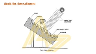
(a) Flat plate collectors
(b) Focusing collectors
It has thefollowing components:
(a) Absorbing plate:
• Made of Copper, Aluminium or steel.
• It is coated with material to enhance the absorption of solar radiation.
• From the absorbing plates heat is transferred to tubes which carry either water or air.
(b) Transparent covers :
• Sheets of solar radiation transmitting materials placed above the absorbing plate.
• They allow solar energy to reach the absorbing plate while reducing convection, conduction and re-radiation heat losses.
(c) Insulation :
• It minimizes and protects the absorbing plate from heat losses.
10.
Working :
• Sun’srays falling on the transparent covers are transmitted to the absorbing plate.
• The absorbing plate usually of Cu, Al or galvanized iron is painted dead black for maximum absorption.
• The collector (plate) will absorb the sun energy and transfer it to the fluid in the pipe beneath the collector plate.
• Use of flat mirrors on the sides improves the output.
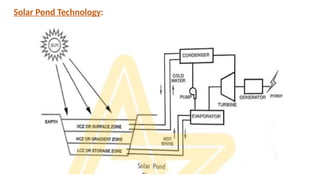
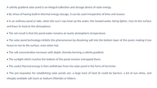
A salinity gradientsolar pond is an integral collection and storage device of solar energy.
• By virtue of having built-in thermal energy storage, it can be used irrespective of time and season.
• In an ordinary pond or lake, when the sun's rays heat up the water, this heated water, being lighter, rises to the surface
and loses its heat to the atmosphere.
• The net result is that the pond water remains at nearly atmospheric temperature.
• The solar pond technology inhibits this phenomenon by dissolving salt into the bottom layer of this pond, making it too
heavy to rise to the surface, even when hot.
• The salt concentration increases with depth, thereby forming a salinity gradient.
• The sunlight which reaches the bottom of the pond remains entrapped there.
• The useful thermal energy is then withdrawn from the solar pond in the form of hot brine
• The pre-requisites for establishing solar ponds are: a large tract of land (it could be barren), a lot of sun shine, and
cheaply available salt (such as Sodium Chloride) or bittern.
13.
• Generally, thereare three main layers. The top layer is cold and has relatively little salt content.
• The bottom layer is hot -- up to 100°C (212°F) -- and is very salty.
• Separating these two layers is the important gradient zone.
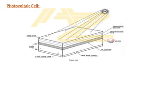
Solar energy canbe directly converted to electrical energy by means of photovoltaic effect. Photovoltaic
effect is defined as the generation of an electromotive force (EMF) as a result of the absorption of ionizing
radiation. Devices which convert sunlight to electricity are known as solar cells or photovoltaic cells. Solar
cells are semiconductors, commonly used are barrier type iron-selenium cells.
• Iron-selenium cells consist of a metal electrode on which a layer of selenium is deposited.
• On the top of this a barrier layer is formed which is coated with a very thin layer of gold.
• The layer of gold serves as a translucent electrode through which light can impinge on the layer below.
• Under the influence of sunlight, a negative charge will build up on the gold electrode and a positive
charge on the bottom electrode
• This difference in charge will produce voltage in proportion to the suns radiant energy incident on it.
16.
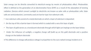
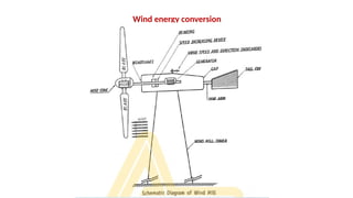
Wind energy
Wind energyis the energy contained in the force of the winds blowing across the earth surface. Wind energy
is defined as the kinetic energy associated with the movement of large masses of air over the earth’s surface.
The circulation of the air in the atmosphere is caused by the non-uniform heating of the earth’s surface by
the sun. The air immediately above warm area expands and becomes less dense. It is then forced upwards
by a cool denser air which flows in from the surrounding areas causing wind.
Power in the wind:
Wind possesses kinetic energy by virtue of its motion. Any device capable of slowing down the mass of
moving air, like a sail or propeller, can extract part of this energy and convert into useful work. The kinetic
energy of one cubic meter of air blowing at a velocity V is given by,
17.
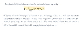
• The rateat which the wind energy is transferred, i.e., wind power is given by,
No device, however well designed can extract all the wind energy because the wind would have to be
brought to halt and this would block the passage of incoming air through the rotor. It has been found that for
maximum power output the exit velocity is equal to one-third of the entrance velocity. Thus a maximum of
60% of the available energy in the wind is converted into mechanical energy.
• A windmillis the oldest device built to convert the wind energy into mechanical energy used for grinding,
milling and pumping applications.
• It consists of a rotor fitted with large sized blades(avg 80 m) and a tower (avg 200m). Now improvement in
performance is achieved by applying sound engineering and aerodynamic principles.
• Now a days the wind energy is used to produce electrical energy. Wind energy is converted into
mechanical energy in wind turbines.
• These wind turbines are coupled to generators and the mechanical energy is converted into electrical
energy.
• The preferred wind speed for optimum generation of power is around 44 km/h.
20.
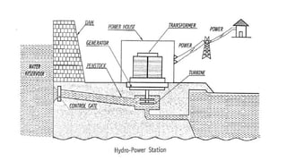
Hydro Power Plants
•In hydroelectric power plants the potential energy of water due to its high location is
converted into electrical energy. The total power generation capacity of the hydroelectric
power plants depends on the head of water and volume of water flowing towards the
water turbine.
• The hydroelectric power plant, also called as dam or hydro power plant, is used for
generation of electricity from water on large scale basis. The dam is built across the large
river that has sufficient quantity of water throughout the river. In certain cases where the
river is very large, more than one dam can built across the river at different locations.
22.
Working Principle ofHydroelectric Power plant
The water flowing in the river possesses two type of energy:
• The kinetic energy due to flow of water and
• Potential energy due to the height of water.
• The kinetic energy and potential energy of water is utilized to generate electricity.
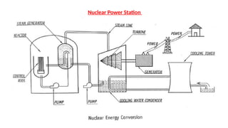
The schematic diagramof nuclear power station is shown in figure. A generating station in which nuclear
energy is converted into electrical energy is known as nuclear power station. The main components of this
station are nuclear reactor, heat exchanger or steam generator, steam or gas turbine, AC generator and
exciter, and condenser.
The reactor of a nuclear power plant is similar to the furnace in a steam power plant. The heat liberated in
the reactor due to the nuclear fission of the fuel is taken up by the coolant circulating in the reactor. A hot
coolant leaves the reactor at top and then flows through the tubes of heat exchanger and transfers its heat
to the feed water on its way. The steam produced in the heat exchanger is passed through the turbine and
after the work has done by the expansion of steam in the turbine, steam leaves the turbine and flows to the
condenser. The mechanical or rotating energy developed by the turbine is transferred to the generator which
in turn generates the electrical energy and supplies to the bus through a step-up transformer, a circuit
breaker, and an isolator. Pumps are provided to maintain the flow of coolant, condensate, and feed water.
25.
Introduction to Bio-fuels
BioFuels are liquid fuels which are derived from biomass or bio waste. Bio fuels are produced from sugar crops, starch crops,
oilseed crops and animal fats.
The most common first-generation biofuels are:
• Biodiesel: extraction with or without esterification of vegetable oils from seeds of plants like soybean, oil palm, oilseed rape and
sunflower or residues including animal fats derived from rendering applied as fuel in diesel engines.
• Bioethanol: fermentation of simple sugars from sugar crops like sugarcane or from starch crops like maize and wheat applied as
fuel in petrol engines
• Bio-oil: thermo-chemical conversion of biomass. A process still in the development phase
• Biogas: anaerobic fermentation or organic waste, animal manures, crop residues an energy crops applied as fuel in engines
suitable for compressed natural gas.
• Biochemical: modification of the bio-ethanol fermentation process including a pretreatment procedure
• Thermo chemical: modification of the bio-oil process to produce syngas and methanol, Fisher-Tropsch diesel or dimethyl ether
(DME).
26.
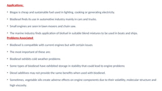
Applications:
• Biogas ischeap and sustainable fuel used in lighting, cooking or generating electricity.
• Biodiesel finds its use in automotive industry mainly in cars and trucks.
• Small engines are seen in lawn movers and chain saw.
• The marine industry finds application of biofuel in suitable blend mixtures to be used in boats and ships.
Problems Associated
• Biodiesel is compatible with current engines but with certain issues
• The most important of these are:
• Biodiesel exhibits cold weather problems
• Some types of biodiesel have exhibited storage in stability that could lead to engine problems
• Diesel additives may not provide the same benefits when used with biodiesel.
• Sometimes, vegetable oils create adverse effects on engine components due to their volatility, molecular structure and
high viscosity.
28.
Global Warming
Global warmingis a gradual increase in the overall temperature of the earth's atmosphere generally
attributed to the greenhouse effect caused by increased levels of carbon dioxide, CFCs, and other pollutants.
Causes for Global Warming:
One of the biggest issues facing us right now is global warming. Its effects on animals and on agriculture are
indeed frightening, and the effects on the human population are even scarier. The facts about global
warming are often debated in politics and the media, but, unfortunately, even if we disagree about the
causes, global warming effects are real, global, and measurable. The causes are mainly from us, the human
race, and the effects on us will be severe.
• Carbon dioxide emissions from fossil fuel burning power plants: Our ever increasing addiction to
electricity from coal burning power plants releases enormous amounts of carbon dioxide into the
atmosphere.
29.
Carbon dioxide emissionsfrom burning gasoline for transportation: With our population growing
at an alarming rate, the demand for more cars and consumer goods means that we are increasing
the use of fossil fuels for transportation and manufacturing.
Methane emissions from animals, agriculture such as rice paddies, and from Arctic seabed's:
Methane is another extremely potent greenhouse gas, ranking right behind CO2. When organic
matter is broken down by bacteria under oxygen-starved conditions (anaerobic decomposition) as
in rice paddies, methane is produced. The process also takes place in the intestines of herbivorous
animals, and with the increase in the amount of concentrated livestock production, the levels of
methane released into the atmosphere is increasing. Another source of methane is methane
clathrate, a compound containing large amounts of methane trapped in the crystal structure of ice.
As methane escapes from the Arctic seabed, the rate of global warming will increase significantly.
30.
Deforestation, especially tropicalforests for wood, pulp, and farmland: The use of forests for fuel
(both wood and for charcoal) is one cause of deforestation, but in the first world, our appetite for wood
and paper products, our consumption of livestock grazed on former forest land, and the use of tropical
forest lands for commodities like palm oil plantations contributes to the mass deforestation of our
world. Forests remove and store carbon dioxide from the atmosphere, and this deforestation releases
large amounts of carbon, as well as reducing the amount of carbon capture on the planet.
Increase in usage of chemical fertilizers on croplands: In the last half of the 20th century, the use of
chemical fertilizers (as opposed to the historical use of animal manure) has risen dramatically. The high
rate of application of nitrogen-rich fertilizers has effects on the heat storage of cropland (nitrogen
oxides have 300 times more heat-trapping capacity per unit of volume than carbon dioxide) and the
run-off of excess fertilizers creates ‘dead-zones’ in our oceans. In addition to these effects, high nitrate
levels in groundwater due to over-fertilization are cause for concern for human health.
31.
Effects for GlobalWarming
• Higher temperatures: Every continent has warmed substantially since the 1950s. There are more hot days
and fewer cold days, on average, and the hot days are hotter.
• Heavier storms: The world's atmosphere can hold more moisture as it warms. As a result, the overall
number of heavier storms has likely increased since midcentury, particularly in North America and Europe
(though there's plenty of regional variation).
• Heat waves: Heat waves have likely become longer and more frequent around the world over the past 50
years, particularly in Europe, Asia, and Australia.
• Shrinking sea ice: The extent of sea ice in the Arctic has shrunk since 1979, by between 3.5 percent and
4.1 percent per decade, on average. Summer sea ice has dwindled even more rapidly.
• Shrinking glaciers: Glaciers around the world have, on average, been losing ice since the 1970s. In some
areas, that is reducing the amount of available freshwater.
32.
• Sea-level rise:Global sea levels rose 25 centimeters (9.8 inches) in the 19th and 20th centuries, after
2,000 years of relatively little change. The pace of sea-level rise has continued to increase in recent
decades. Sea-level rise is caused by both the thermal expansion of the oceans — as water warms up,
it expands — and the melting of glaciers and ice sheets.
• Food supply: A hotter climate can be both good for crops (it lengthens the growing season, and more
carbon dioxide can increase photosynthesis) and bad for crops (excess heat can damage plants). The
IPCC found that global warming was currently benefiting crops in some high-latitude areas, but that
negative effects were becoming increasingly common worldwide.
• Shifting species: Many land and marine species have had to shift their geographic ranges in response
to warmer temperatures. So far, only a few extinctions have been linked to global warming, such as
certain frog species in Central America.
33.
Greenhouse Effect
The greenhouseeffect is the process by which radiation from a planet's atmosphere warms the
planet's surface to a temperature above what it would be without its atmosphere. If a planet's
atmosphere contains radiative active gases (i.e., greenhouse gases) they will radiate energy in all
directions. Part of this radiation is directed towards the surface, warming it. The intensity of the
downward radiation – that is, the strength of the greenhouse effect – will depend on the
atmosphere's temperature and on the amount of greenhouse gases that the atmosphere contains.
Earth’s natural greenhouse effect is critical to supporting life. Human activities, mainly the burning
of fossil fuels and clearing of forests, have strengthened the greenhouse effect and caused global
warming.
34.
Ozone Layer
A layerin the earth's stratosphere at an altitude of about 10 km (6.2 miles) containing a high concentration
of ozone, which absorbs most of the ultraviolet radiation reaching the earth from the sun.
Causes for Ozone Layer Depletion:
The decrease in ozone concentration in the middle layers of the atmosphere – mainly in the stratosphere – is
extremely damaging to life on earth, and is largely caused by emissions of halogenated hydrocarbons
produced by man, CFCs, HCFCs, halons, carbon tetrachloride and methyl bromide. For this reason, such
substances are commonly referred to as Substances that Deplete the Ozone Layer (ODS).
• Chlorofluorocarbons (CFCs) : They are compounds formed by chlorine, fluorine and carbon. They are often
used as refrigerants, solvents, and for the manufacture of spongy plastics. When the chemicals reached
the earth’s stratosphere, they reacted with Ultraviolet radiation, which caused them to break down and
release Chlorine and Bromine into the earth’s ozone layer.
35.
• Hydrochlorofluorocarbons (HCFCs): Compounds formed by H, Cl, F and C. They are being used as
substitutes for CFCs because many of their properties are similar and are less harmful to ozone by
having a shorter half-life and releasing fewer Cl atoms
• Halons : They are compounds formed by Br, F and C. Because of their ability to put out fires are
used in fire extinguishers, although their manufacture and use is prohibited in many countries
because of their ozone-depleting action. Their ability to harm the ozone layer is very high
because they contain Br which is a much more effective atom destroying ozone than the Cl.
• Methyl bromide (CH3Br) :It is a very effective pesticide that is used to fumigate soils and in many
crops.
• Carbon tetra-chloride (CCl4): It is a compound that has been widely used as a raw material in
many industries, for example, to manufacture CFCs and as a solvent.
36.
Effects of OzoneLayer Depletion
• Skin Cancer: Today, it is estimated that skin cancer rates increased due to the decrease in stratospheric
ozone (ozone layer). The most common type of skin cancer, called non-melanoma, is the cause of
exposures to UV-B radiation for several years.
• Effects on aquatic ecosystems: The loss of phytoplankton, the basis of the marine food chain, has been
observed as the cause of the increase in ultraviolet radiation.
• Effects on terrestrial ecosystems:
• Animals: For some species, an increase in UV-B radiation implies the formation of skin cancer. This has
been studied in goats, cows, cats, dogs, sheep and laboratory animals and is probably pointing out that
this is a common feature of several species. Infections in cattle can be aggravated by an increase in UV-B
radiation.
37.
• Plants: Inmany plants UV-B radiation can have the following adverse effects: alter its shape and damage
plant growth; Reduce tree growth; Change flowering times; Make plants more vulnerable to disease and
produce toxic substances. There could even be losses of biodiversity and species.
38.
MODULE-2
Machine Tool Operations
Aproduct or part can be manufactured by various processes like casting, forging, machining
etc. Machining is an operation that can be carried out manually or by machine, which involves
removal of excess material from the raw material so as to get the required shape and size. So
any machine involved in metal cutting is known as a ‘Machine tools’ and the process is called
‘Machining’.
“A machine tool may be defined as a power driven machine to produce a product by removing
the excess material using a cutting tool”. The excess material removed is called as chips. Some
of the important machine tools are lathe, drilling machine, milling machine, grinding machine,
shaper etc.
39.
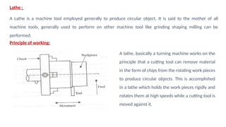
Lathe :
A Latheis a machine tool employed generally to produce circular object. It is said to the mother of all
machine tools, generally used to perform on other machine tool like grinding shaping milling can be
performed.
Principle of working:
A lathe, basically a turning machine works on the
principle that a cutting tool can remove material
in the form of chips from the rotating work pieces
to produce circular objects. This is accomplished
in a lathe which holds the work pieces rigidly and
rotates them at high speeds while a cutting tool is
moved against it.
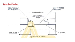
The size ofa lathe is specified by the following as shown in Fig
1. Maximum diameter of the work piece that can be revolved over the lathe bed. Instead of
this sometimes, the height of the centres above the lathe bed is also specified. One of these
specifications is given by the manufacturers; however both of them are loosely called as
"Swing of the lathe".
2. The Maximum diameter and the width of the workpiece that can swing when the lathe has a
gap bed.
3. The maximum length of the workpiece that can be mounted between the centres.
4. Overall length of the bed. It is the total length of the lathe itself.
42.
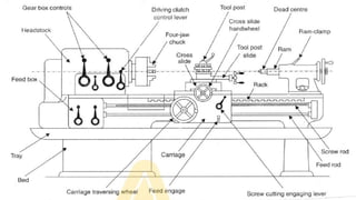
Major parts ofa Lathe:
1. Bed
2. Head stock
3. Tail stock
4. Carriage assembly
5. Feed rod
6. Lead screw
44.
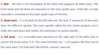
1. Bed –the bed is the foundation of the lathe and supports all other parts. The
head stock and tail stock are mounted on the inner guide ways, while the carriage
assembly is mounted on the outer guide ways of the bed.
2. Head stock – it is located on the left side over the bed. It comprises of the main
drive for different speeds. The main spindle called the live center projects out it
holds the work piece and rotates the work piece at various speeds.
3. Tail stock – it is a movable part mounted on the right side of the lathe bed. It
carries the dead center in it. The main functions are –1.To support the free end of
the work piece 2.To hold tools like drill bit, reamers, taps etc.
45.
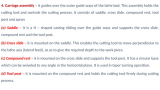
4. Carriage assembly– it guides over the outer guide ways of the lathe bed. This assembly holds the
cutting tool and controls the cutting process. It consists of saddle, cross slide, compound rest, tool
post and apron
(a) Saddle – It is a H – shaped casting sliding over the guide ways and supports the cross slide,
compound rest and the tool post.
(b) Cross slide – it is mounted on the saddle. This enables the cutting tool to move perpendicular to
the lathe axis (lateral feed), so as to give the required depth to the work piece.
(c) Compound rest – it is mounted on the cross slide and supports the tool post. It has a circular base
which can be swiveled to any angle in the horizontal plane. It is used in taper turning operation.
(d) Tool post – it is mounted on the compound rest and holds the cutting tool firmly during cutting
process.
46.
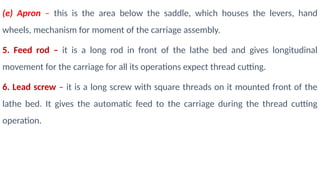
(e) Apron –this is the area below the saddle, which houses the levers, hand
wheels, mechanism for moment of the carriage assembly.
5. Feed rod – it is a long rod in front of the lathe bed and gives longitudinal
movement for the carriage for all its operations expect thread cutting.
6. Lead screw – it is a long screw with square threads on it mounted front of the
lathe bed. It gives the automatic feed to the carriage during the thread cutting
operation.
47.
Operations on Lathe
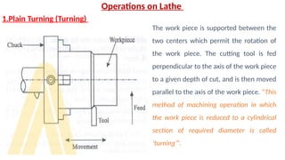
1.PlainTurning (Turning)
The work piece is supported between the
two centers which permit the rotation of
the work piece. The cutting tool is fed
perpendicular to the axis of the work piece
to a given depth of cut, and is then moved
parallel to the axis of the work piece. “This
method of machining operation in which
the work piece is reduced to a cylindrical
section of required diameter is called
‘turning’”.
48.
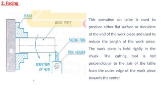
2. Facing
This operationon lathe is used to
produce either flat surface or shoulders
at the end of the work piece and used to
reduce the Length of the work piece.
The work piece is held rigidly in the
chuck. The cutting tool is fed
perpendicular to the axis of the lathe
from the outer edge of the work piece
towards the center.
49.
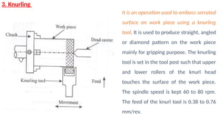
3. Knurling
It isan operation used to emboss serrated
surface on work piece using a knurling
tool. It is used to produce straight, angled
or diamond pattern on the work piece
mainly for gripping purpose. The knurling
tool is set in the tool post such that upper
and lower rollers of the knurl head
touches the surface of the work piece.
The spindle speed is kept 60 to 80 rpm.
The feed of the knurl tool is 0.38 to 0.76
mm/rev.
50.
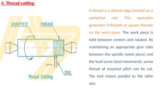
4. Thread cutting
Athread is a helical ridge formed on a
cylindrical rod. This operation
generates V-threads or square threads
on the work piece. The work piece is
held between centers and rotated. By
maintaining an appropriate gear ratio
between the spindle (work piece) and
the lead screw (tool movement), screw
thread of required pitch can be cut.
The tool moves parallel to the lathe
axis.
51.
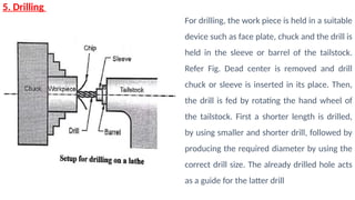
5. Drilling
For drilling,the work piece is held in a suitable
device such as face plate, chuck and the drill is
held in the sleeve or barrel of the tailstock.
Refer Fig. Dead center is removed and drill
chuck or sleeve is inserted in its place. Then,
the drill is fed by rotating the hand wheel of
the tailstock. First a shorter length is drilled,
by using smaller and shorter drill, followed by
producing the required diameter by using the
correct drill size. The already drilled hole acts
as a guide for the latter drill
52.
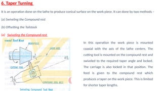
6. Taper Turning
Itis an operation done on the lathe to produce conical surface on the work piece. It can done by two methods –
(a) Swiveling the Compound rest
(b) Offsetting the Tailstock
(a) Swiveling the Compound rest
In this operation the work piece is mounted
coaxial with the axis of the lathe centers. The
cutting tool is mounted on the compound rest and
swiveled to the required taper angle and locked.
The carriage is also locked in that position. The
feed is given to the compound rest which
produces a taper on the work piece. This is limited
for shorter taper lengths.
53.
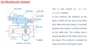
(b) Offsetting theTailstock
This is also known as “set over
tailstock” method.
In this method, the tailstock of the
lathe is offset to the axis of the lathe
bed. When the work piece is mounted
between the centers, it will be inclined
to the lathe bed. The cutting tool is
moved parallel to the lathe bed to cut
the taper. This method is suitable for
long work pieces having less taper.
54.
Drilling Machine
Drilling machineis one of the most important machine tools in a workshop. It was designed to
produce a cylindrical hole of required diameter and depth on metal workpieces. Though holes
can be made by different machine tools in a shop, drilling machine is designed specifically to
perform the operation of drilling and similar operations. Drilling can be done easily at a low cost
in a shorter period of time in a drilling machine.
Drilling can be called as the operation of producing a cylindrical hole of required diameter and
depth by removing metal by the rotating edges of a drill. The cutting tool known as drill is fitted
into the spindle of the drilling machine. A mark of indentation is made at the required location
with a centre punch. The rotating drill is pressed at the location and is fed into the work. The
hole can be made up to a required depth.
55.
Types of drillingmachines:
Drilling machines are manufactured in different types and sizes according to the type of operation,
amount of feed, depth of cut, spindle speeds, method of spindle movement and the required accuracy.
The different types of drilling machines are:
1. Portable drilling machine (or) Hand drilling machine:
2. Sensitive drilling machine (or) Bench drilling machine
3. Upright drilling machine
4. Radial drilling machine
5. Gang drilling machine
6. Multiple spindle drilling machine
7. Deep hole drilling machine
56.
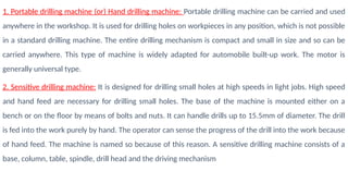
1. Portable drillingmachine (or) Hand drilling machine: Portable drilling machine can be carried and used
anywhere in the workshop. It is used for drilling holes on workpieces in any position, which is not possible
in a standard drilling machine. The entire drilling mechanism is compact and small in size and so can be
carried anywhere. This type of machine is widely adapted for automobile built-up work. The motor is
generally universal type.
2. Sensitive drilling machine: It is designed for drilling small holes at high speeds in light jobs. High speed
and hand feed are necessary for drilling small holes. The base of the machine is mounted either on a
bench or on the floor by means of bolts and nuts. It can handle drills up to 15.5mm of diameter. The drill
is fed into the work purely by hand. The operator can sense the progress of the drill into the work because
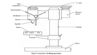
of hand feed. The machine is named so because of this reason. A sensitive drilling machine consists of a
base, column, table, spindle, drill head and the driving mechanism
58.
1. Base: Thebase is made of cast iron and so can withstand vibrations. It may be mounted on a bench or on
the floor. It supports all the other parts of the machine on it.
2. Column: The column stands vertically on the base at one end. It supports the work table and the drill head.
The drill head has drill spindle and the driving motor on either side of the column.
3. Table: The table is mounted on the vertical column and can be adjusted up and down on it. The table has ‘T’-
slots on it for holding the workpieces or to hold any other work holding device. The table can be adjusted
vertically to accommodate workpieces of different heights and can be clamped at the required position.
4. Drill head: Drill head is mounted on the top side of the column. The drill spindle and the driving motor are
connected by means of a V-belt and cone pulleys. The motion is transmitted to the spindle from the motor
by the belt. The pinion attached to the handle meshes with the rack on the sleeve of the spindle for
providing the drill the required down feed. There is no power feed arrangement in this machine. The spindle
rotates at a speed ranging from 50 to 2000 r.p.m.
59.
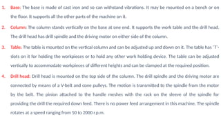
3. Upright drillingmachine
The upright drilling machine is
designed for handling medium sized
workpieces. Though it looks like a
sensitive drilling machine, it is larger
and heavier than a sensitive drilling
machine. Holes of diameter up to
50mm can be made with this type of
machine. Besides, it is supplied with
power feed arrangement. For drilling
different types of work, the machine
is provided with a number of spindle
60.
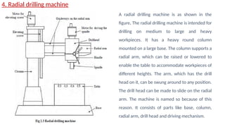
4. Radial drillingmachine
A radial drilling machine is as shown in the
figure. The radial drilling machine is intended for
drilling on medium to large and heavy
workpieces. It has a heavy round column
mounted on a large base. The column supports a
radial arm, which can be raised or lowered to
enable the table to accommodate workpieces of
different heights. The arm, which has the drill
head on it, can be swung around to any position.
The drill head can be made to slide on the radial
arm. The machine is named so because of this
reason. It consists of parts like base, column,
radial arm, drill head and driving mechanism.
61.
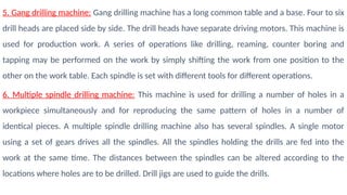
5. Gang drillingmachine: Gang drilling machine has a long common table and a base. Four to six
drill heads are placed side by side. The drill heads have separate driving motors. This machine is
used for production work. A series of operations like drilling, reaming, counter boring and
tapping may be performed on the work by simply shifting the work from one position to the
other on the work table. Each spindle is set with different tools for different operations.
6. Multiple spindle drilling machine: This machine is used for drilling a number of holes in a
workpiece simultaneously and for reproducing the same pattern of holes in a number of
identical pieces. A multiple spindle drilling machine also has several spindles. A single motor
using a set of gears drives all the spindles. All the spindles holding the drills are fed into the
work at the same time. The distances between the spindles can be altered according to the
locations where holes are to be drilled. Drill jigs are used to guide the drills.
62.
7. Deep holedrilling machine: A special machine and drills are required to drill
deeper holes in barrels of gun, spindles and connecting rods. The machine
designed for this purpose is known as deep hole drilling machine. High cutting
speeds and less feed are necessary to drill deep holes. A non rotating drill is fed
slowly into the rotating work at high speeds. Coolant should be used while drilling
in this machine.
63.
Drilling machine operations:
Thoughdrilling is the primary operation performed in a drilling machine, a number of similar operations are also
performed on holes using different tools. The different operations that can be performed in a drilling machine are:
1. Drilling
2. Reaming
3. Boring
4. Counter boring
5. Countersinking
6. Spot facing
7. Tapping
8. Trepanning
64.
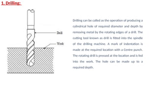
1. Drilling:
Drilling canbe called as the operation of producing a
cylindrical hole of required diameter and depth by
removing metal by the rotating edges of a drill. The
cutting tool known as drill is fitted into the spindle
of the drilling machine. A mark of indentation is
made at the required location with a Centre punch.
The rotating drill is pressed at the location and is fed
into the work. The hole can be made up to a
required depth.
65.
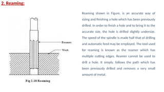
2. Reaming:
Reaming shownin Figure, is an accurate way of
sizing and finishing a hole which has been previously
drilled. In order to finish a hole and to bring it to the
accurate size, the hole is drilled slightly undersize.
The speed of the spindle is made half that of drilling
and automatic feed may be employed. The tool used
for reaming is known as the reamer which has
multiple cutting edges. Reamer cannot be used to
drill a hole. It simply. follows the path which has
been previously drilled and removes a very small
amount of metal.
66.
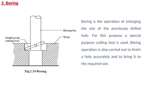
3. Boring
Boring isthe operation of enlarging
the size of the previously drilled
hole. For this purpose a special
purpose cutting tool is used. Boring
operation is also carried out to finish
a hole accurately and to bring it to
the required size.
67.
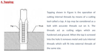
4. Tapping:
Tapping shownin Figure is the operation of
cutting internal threads by means of a cutting
tool called a tap. A tap may be considered as a
bolt with accurate threads cut on it. The
threads act as cutting edges which are
hardened and ground. When the tap is screwed
into the hole it removes metal and cuts internal
threads which will fit into external threads of
the same size.
69.
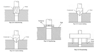
5. Counter Boring:It is an operation for enlarging a pre-drilled hole at one end to the required
depth using a counter bore tool to form a shoulder as shown in the figure.
6.Countersinking: It is an operation to produce conical surface(seating) at one end of the pre-
drilled hole using a counter sunk tool as shown in the figure.
7. Spot facing: It is an operation to produce a smooth flat circular surface on a raised pad of a
machine part or around the drilled hole in tubular components using a spot facing tool as shown
in the figure.
8. Trepanning: It is a technique used for drilling larger hole diameters where machine power is
limited as it is not as power consuming as conventional drilling where the entire hole is
converted into chips. The trepanning tool does not machine the whole diameter, only a ring at
the periphery.
70.
MILLING
Milling is ametal removal process in which the work piece is fed into a revolving cutting tool, thereby
removing excess material. The cutting tool is known as milling cutter which is a multipoint cutting tool.
Milling Machine – It is a power operated machine tool in which the work piece mounted on the table
is fed against the milling cutter to get the required shape.
Principle of Milling:
In milling, the work piece is rigidly held on table and is slowly fed into the uniformly rotating cutter to
get the required shape.
The work piece can be fed in either direction of the rotating cutter.
(a) Up milling (conventional)
(b) Down milling (climb)
71.
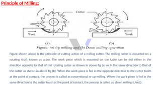
Principle of Milling:
Figureshown above is the principle of cutting action of a milling cutter. The milling cutter is mounted on a
rotating shaft known as arbor. The work piece which is mounted on the table can be fed either in the
direction opposite to that of the rotating cutter as shown in above fig (a) or in the same direction to that of
the cutter as shown in above fig (b). When the work piece is fed in the opposite direction to the cutter tooth
at the point of contact, the process is called as conventional or up-milling. When the work piece is fed in the
same direction to the cutter tooth at the point of contact, the process is called as down milling (climb).
72.
Classification of MillingMachine:
The milling machines are broadly classified into:
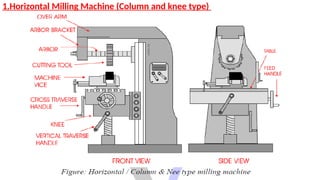
1. Plain or Horizontal Type of Milling Machine
2. Vertical Milling Machine
3. Universal Milling Machine
4. Planer Type Milling Machine
5. Profile Cutting Milling Machine
Milling machine hassome principal parts. Their understanding would help us in
understanding how the machine operates. The various parts are
1. Base
2. Column
3. Arbor
4. Knee
5. Saddle
6. Table
7. Overhanging arm
8. Driving and feeding Mechanism
75.
• Base: Baseforms the foundation of the machine tool. It’s a rectangular casting
made up of Cast Iron. The one end of the base houses the Column and other end
of the base contains a space for table elevating screw or knee supporting screw.
• Column: The column is another rectangular casting mounted on one end of the
base. The column is ribbed heavily in order to support the knee. The front vertical
face of the column is provided with a vertical slide, which may be of square or
dovetail type. The knee moves up and down on this slide. At the top of the
column, an internal dovetail slide accommodates a cast overarm. The overarm
supports the arbor. It also houses the driving mechanism to drive the spindle and
feeding mechanism to feed the table.
76.
• Arbor: Thearbor is a horizontal shaft provided with a straight body and tapered shank. On the
straight portion of arbor, rotary cutters are mounted. The tapered end of the arbor fits into the
tapered hole of the spindle. The other end of the arbor is mounted in a bearing housed in the
projecting overarm. The knee of the casting mounted on the front vertical slide of the column and
is moved up or down by an elevating screw. The upper face of the knee is provided with guide
ways so as to mount the saddle.
• Knee: The Knee is a casting mounted on the front vertical slide of the column and is moved up or
down by an elevating screw. The upper face of the knee is provided with guide ways so as to
mount the saddle.
• Saddle: The saddle is casting provided with two slides one at the top and the other at the bottom,
which are exactly right angles to each other. The lower slide fits within the guideways on the top of
the knee and the upper slide receives the dovetail guides provided on the bottom of the table.
77.
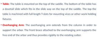
• Table: Thetable is mounted on the top of the saddle. The bottom of the table has
a dovetail slide which fits in the slide way on the top of the saddle. The top the
table is machined with full length T-slots for mounting vices or other work holding
fixtures.
• Overhanging Arm: The overhanging arm extends from the column in order to
support the arbor. The front brace attached to the overhanging arm supports the
free end of the arbor and thus provides rigidity to the rotating cutter.
78.
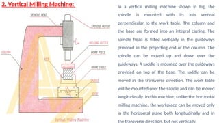
2. Vertical MillingMachine: In a vertical milling machine shown in Fig, the
spindle is mounted with its axis vertical
perpendicular to the work table. The column and
the base are formed into an integral casting. The
spindle head is fitted vertically in the guideways
provided in the projecting end of the column. The
spindle can be moved up and down over the
guideways. A saddle is mounted over the guideways
provided on top of the base. The saddle can be
moved in the transverse direction. The work table
will be mounted over the saddle and can be moved
longitudinally. In-this machine, unlike the horizontal
milling machine, the workpiece can be moved only
in the horizontal plane both longitudinally and in
the transverse direction, but not vertically.
79.
Milling Operations:
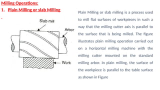
1. PlainMilling or slab Milling Plain Milling or slab milling is a process used
to mill flat surfaces of workpieces in such a
way that the milling cutter axis is parallel to
the surface that is being milled. The figure
illustrates plain milling operation carried out
on a horizontal milling machine with the
milling cutter mounted on the standard
milling arbor. In plain milling, the surface of
the workpiece is parallel to the table surface
as shown in Figure
80.
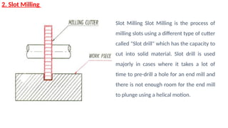
2. Slot Milling
SlotMilling Slot Milling is the process of
milling slots using a different type of cutter
called "Slot drill" which has the capacity to
cut into solid material. Slot drill is used
majorly in cases where it takes a lot of
time to pre-drill a hole for an end mill and
there is not enough room for the end mill
to plunge using a helical motion.
81.
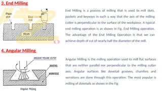
3. End Milling
4.Angular Milling
End Milling is a process of milling that is used to mill slots,
pockets and keyways in such a way that the axis of the milling
cutter is perpendicular to the surface of the workpiece. A typical
end milling operation is as shown in Fig. End Milling operation.
The advantage of the End Milling Operation is that we can
achieve depth of cut of nearly half the diameter of the mill.
Angular Milling is the milling operation used to mill flat surfaces
that are neither parallel nor perpendicular to the milling cutter
axis. Angular surfaces like dovetail grooves, chamfers and
serrations are done through this operation. The most popular is
milling of dovetails as shown in the Fig
82.
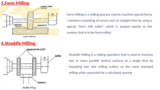
5.Form Milling
6.Straddle Milling
FormMilling is a milling process used to machine special forms
/ contours consisting of curves and /or straight lines by using a
special "form mill cutter" which is shaped exactly to the
contour that is to be form-milled.
Straddle Milling is a milling operation that is used to machine
two or more parallel vertical surfaces at a single time by
mounting two side milling cutters on the same standard
milling arbor separated by a calculated spacing