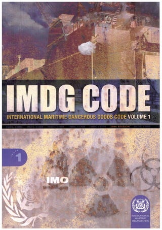
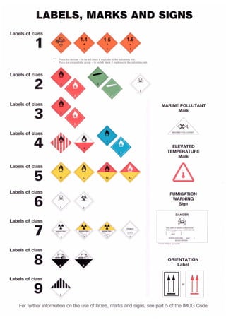
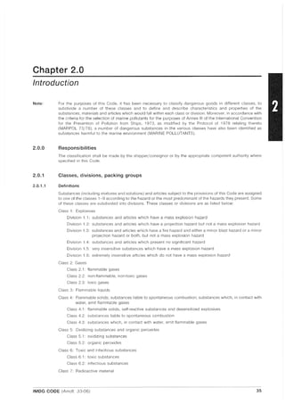
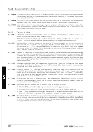
The document establishes legally binding regulations concerning the transportation of dangerous goods under the International Maritime Dangerous Goods (IMDG) Code, adhering to international safety standards. It outlines various classes of dangerous goods, safety protocols, packaging specifications, and required documentation for compliance. Penalties for noncompliance may apply, and the IMDG Code is mandatory for ocean transport of hazardous materials as of January 2004.


![Contents
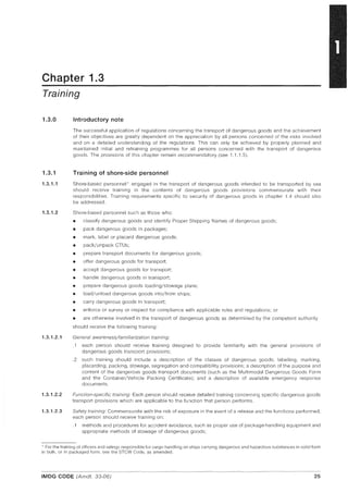
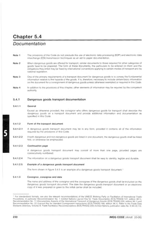
Chapter 5.2 Marking and labelling of packages including IBCs
5.2.1
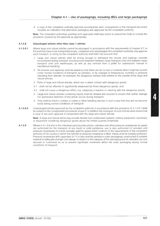
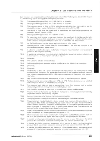
5.2.2
Marking of packages including IBCs .
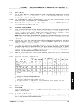
Labelling of packages including IBCs.
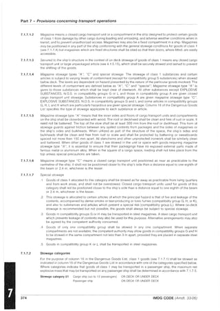
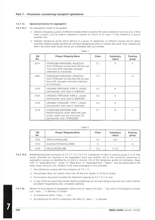
Chapter 5.3 Placarding and marking of cargo transport units
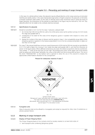
5.3.1 Placarding.
5.3.2 Marking of cargo transport units
Chapter 5.4 Documentation
5.4.1 Dangerous goods transport documentation
5.4.2 Container/vehicle packing certificate.
5.4.3 Documentation required aboard the ship ..
5.4.4 Other required information and documentation
5.4.5 Multimodal Dangerous Goods Form.
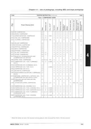
PART 6 - CONSTRUCTION AND TESTING OF PACKAGINGS, INTERMEDIATE BULK
CONTAINERS (IBCs), LARGE PACKAGINGS, PORTABLE TANKS,
MULTIPLE-ELEMENT GAS CONTAINERS (MEGCs) AND
ROAD TANK VEHICLES
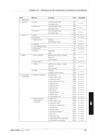
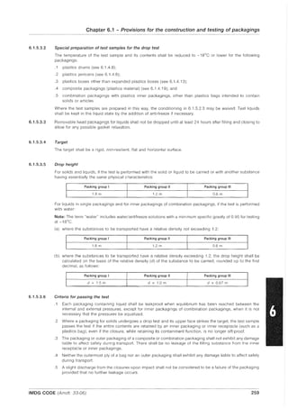
Chapter 6.1 Provisions for the construction and testing of packagings
(other than for class 6.2 substances)
6.1.1 Applicability and general provisions ...... . . . . . . .
6.1.2 Code for designating types of packagings ..
6.1.3 Marking.
6.1.4 Provisions for packagings
6.1.5 Test provisions for packagings.
Chapter 6.2 Provisions for the construction and testing of pressure
receptacles, aerosol dispensers and small receptacles
containing gas (gas cartridges)
6.2.1
6.2.2
6.2.3
General provisions ...................... .
Provisions for UN pressure receptacles ...... .
Provisions for non-UN pressure receptacles ....... .
6.2.4 Provisions for aerosol dispensers and small receptacles
containing gas (gas cartridges) ........................ .
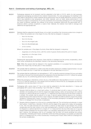
Chapter 6.3 Provisions for the construction and testing
of packagings for class 6.2 substances
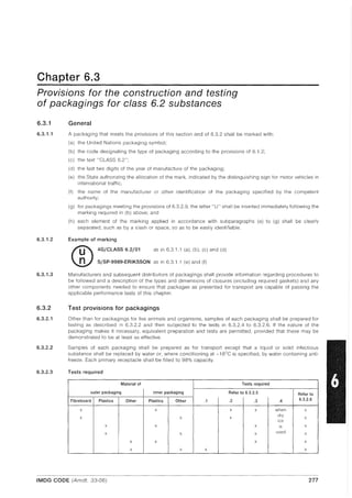
6.3.1
6.3.2
6.3.3
General ............................................... .
Test provisions for packagings........... .
Test report.
Chapter 6.4 Provisions for the construction, testing and approval
of packages and material of class 7
6.4.1 [reserved]
6.4.2 General provisions .............. .
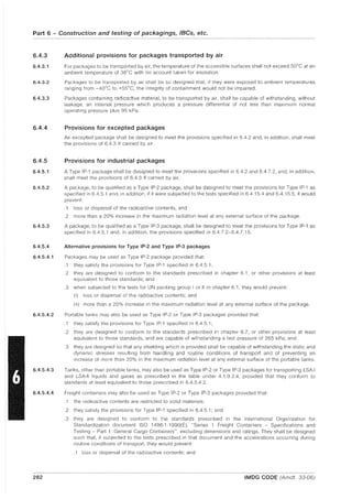
6.4.3 Additional provisions for packages transported by air.
6.4.4 Provisions for excepted packages .
6.4.5 Provisions for industrial packages ...... .
6.4.6 Provisions for packages containing uranium hexafluoride.
6.4.7 Provisions for Type A packages.
6.4.8 Provisions for Type B(U) packages.
Page
217
219
226
227
230
234
235
235
236
243
244
246
248
256
262
265
275
275
277
277
279
281
281
282
282
282
283
283
284
viii IMDG CODE (Amdt. 33-06)](https://image.slidesharecdn.com/imo-161102013454/85/Imo-imdg-1-2006-12-320.jpg)


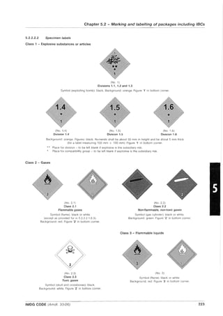
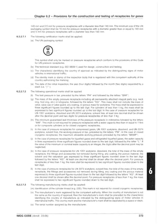
![1.1.2.2
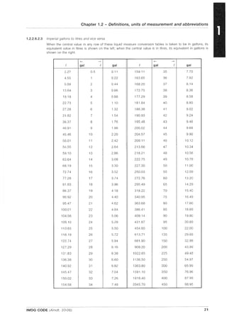
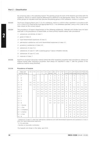
1.1.2.2.1
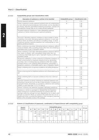
Chapter 1.1 - General provisions
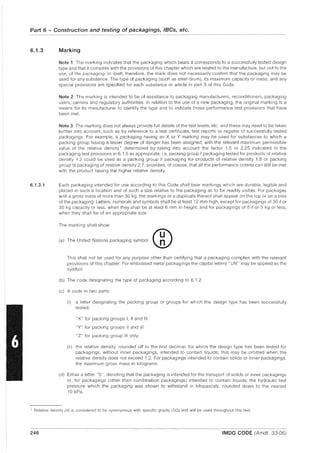
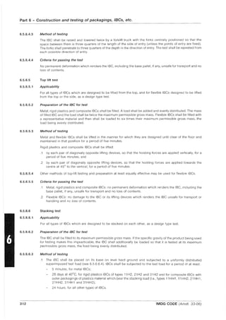
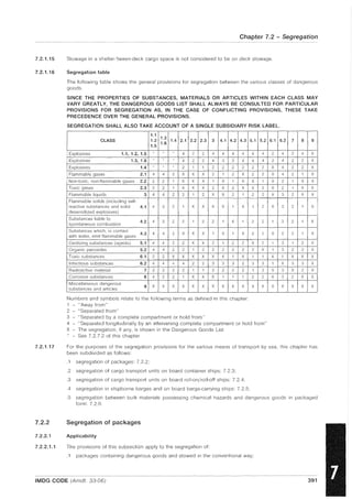
2 The transport doculllents prepared by the shipper shall include, or be accompanied by, a signed
certificate or a declaration that the consignment, as offered for carriage, is properly packaged, ll1arked,
labelled or placarded, as appropriate, and in proper condition for carriage.
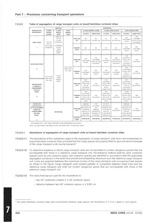
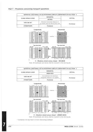
3 The person(s) responsible for the packing/loading of dangerous goods in a cargo tLl1lSport unit*
shall provide a signed container/vehicle packing certificate stating that the cargo in the unit has been
properly packed and secured and that all applic:lble transport requirements have been met. Such a
certificate may be combined with the document referred to in paragraph 2.
4 Where there is due C:luse to suspect that a cargo transport unit in which dangerous goods are
packed is not in compliance with the requirements of paragraph 2 or 3, or where a container/vehicle
packing certificate is not available, the cargo transport unit shall not be accepted for carriage.
5 Each ship carrying dangerous goods in packaged form shall have a speci::d list or manifest setting
forth, in accordance with the cbssificatioll set out in the IMDG Code, the dangerous goods on board
and the location thereof. A detailed stowage plan, which identifies by class and sets out the location of
all dangerous goods on board, may be used in pbce of such a special list or manifest. A copy of one of
these documents shall be made available before departure to the person or organizJtion designated by
the port State authority.
Regulation 5
Ca~~o Securin,~ Manual
Cargo, cargo units'" and cargo transport units, shall be loaded, stowed and secured throughout the
voyage in accordance with the Cargo Securing Manual approved by the Administration. The Cargo
Securing Man~JJl shall be drawn up to a standard at least equivalent to the guidelines developed by the
Organization. +
Regulation 6
Reporting of incidents i1l1/Olvin,<? danJ.;erous goods
When an incident takes place involving the loss or likely loss overboard of dangerous goods in
packaged form into the sea, the master, or other person having charge of the ship, shall report the
particulars of such an incident without delay and to the fullest extent possible to the nearest coastal
State. The report shall be drawn up based on general principles and guidelines developed by the
OrganizationS
2 In the event of the ship referred to in paragraph 1 being abandoned, or in the event of a report
frol11 sllch ;] ship being incomplete or unobtainable, the cOl11p:my, as defined in regulation IX/1.2,
shall, to the fullest extent possible, aSSllme the obligations placed upon the I11Jster by this regulation.
International Convention for the Prevention of Pollution from Ships, 1973/78
Annex III of the International Convention for the Prevention of Pollution from Ships, 1973, as modified by the
Protocol of 1978 relating thereto (MAR POL 73/78), deals with the prevention of pollution by harmful
substances carried by sea in packaged form and is reproduced in full, as revised by the Marine Environment
Protection Committee.'
, Refer to the lnterJutiollal Maritil11e J)angerous Coods (IMJ)C) Code, adopted by the Organizatioll by resolution MSC.122(7S) ']S
amended.
, As defined in the Code of Safe Practice for Cargo Stowage and Securing (CSS Code), 'Idopted by the Orgallization by resolution
A.715(17), "s "lllcndcd.
; Refer to Cuidelines for the prepaLltioll of the Cargo Securing M'1I111,]1 (MSCjCire.745).
*R.cfcr to the C;cllcr~d principles f(n ship reporting systems ;Illd ship reporting rcquin.'lllcllts, illcludillg guidelines f()J- reporting incidellts
involving d'1I1gerous goods, harmful substances and/or Imrine pollutants, adopted by the Org'H1ization by resolution A.S:; 1(20) .
• The original text of Annex III entered into force on 1 July 1992. Since the original text prepared in 1973 was based on the corresponding
regulations of the International Convention for the Safety of Life at Sea (SOlAS), 1960, the MEPC agreed to revise and formally adopt a new
text, taking into account the SOlAS 1974 provisions and explicitly referring to the IMDG Code. The revised text of Annex III was adopted by
resolution MEPC.58(33) and entered into force on 28 February 1994.
IMDG CODE (Amdt. 33-06) 5](https://image.slidesharecdn.com/imo-161102013454/85/Imo-imdg-1-2006-25-320.jpg)
![Part 1 - General provisions, definitions and training
Annex III
Regulations for the Prevention of Pollution by Harmful Substances
Carried by Sea in Packaged Form
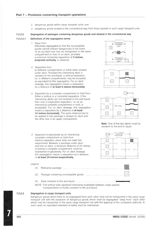
Regulation 1
Application
Unless expressly provided otherwise, the regulations of this Annex apply to all ships carrying
harmful substances in packaged form.
1.1 For the purpose of this Annex, //(//"111/141 slfbstancfs are those substances which are identified as
marine pollutants ill the International Maritime Dangerous Goods (IMDG) Code. A
1.2 Guidelines for the identification of harmful substances in packaged form are given in the
appendix to this Annex.
1.3 For the purposes of this Annex, packagcd.fimn is defined as the forms ofcontainment specified for
harmful substances in the IMDG Code.
2 The transport of h;mnful substances is prohibited except in accordance with the provisions of
this Annex.
3 To supplernent the provisions of this Annex, the Govermnent of each Party to the Convention
shall issue, or cause to be issued, detailed requirements on packing, rnarking, labelling,
documentation, stowage, quantity limitations and exceptions for preventing or minimizing
pollution of the marine environment by harmful substances. *
4 For the purposes of this Annex, empty packagings which have been used previously for the
transport of harmful substances shall themselves be treated as harmful substances unless adequate
precautions have been taken to ensure that they contain no residue that is harmful to the marine
environl11ent.
5 The requirements of this Annex do not apply to ships' stores :l11d equipment.
Regulation 2
Packing
Packages shall be adequate to rninirnize the hazard to the lTlarine environmcnt, having regard to their
specific contents.
Regulation 3
Marking and labelling
Packages containing a harmful substance shall be durably m;lrked with the correct technical
narne (trade names alone shall not be used) and, further, shall be durably marked or labelled to
indicate that the substance is a marine pollutant. Such identification shall be supplemented where
possible by any other means, for example by the use of the relevant United Nations number.
2 The method of marking the correct technical name and affixing labels on packages containing a
harmful substance shall be such that this information will still be identifiable on packages
surviving at least three months' immersion in the sea. In considering suitable marking and
labelling, account shall be taken of the durability of the materials used and of the surtlce of the
package.
3 Packages conttlining small quantities of harmful substances may be excmpted from the marking
requIrements.
, I(efer to the InterIl:ltion:d M:lritillle i):lngerolls Coods (IMDC) Code, as :ldopted by resolution MSC.122(75), as alllClldcd.
I' I(eferellee is Illade to the specific exelllptions provided f(H in the International M:lririllle Dangerolls Coods (IM])C) Code.
6 IMDG CODE (Amdt. 33·06)](https://image.slidesharecdn.com/imo-161102013454/85/Imo-imdg-1-2006-26-320.jpg)
![Regulation 4
Documentation*
Chapter 1.1 - General provisions
In all documents relating to the transport ofh3r111ful substances by sea where such substances are
named, the correct technical narne of each such substance shall be used (trade names alone shall
not be used) and the substance further identified by the addition of the words "MARINE
POLLUTANT".
2 The shipping documents supplied by the shipper shall include, or be accompanied by, a signed
certificate or declaration tint the shipment offered for transport is properly packaged and
marked, labelled or placarded as appropriate ;md in proper condition for transport to Illinimize
the hazard to the marine environment.
3 Each ship carrying harmful substances shall have a special list or rnanifest setting f()rth the
harmful substances on board and the location thereof. A detailed stowage plan which sets out the
location of the harmful substances on board may be used in place of such special list or manifest.
Copies of such documents shall also be retained on shore by the owner of the ship or his
representative until the harmful substances arc unloaded. A copy ofone of these docllments shall
be rnade available before departure to the person or organization designated by the Port State
authority.
4 When the ship c:1rries a special list or manifest or a detailed stowage plan, required for the
transport ofdangerous goods by the International Convention for the Safety of Life at Sea, 1<)74,
as amended, the documents required by this regulation may be combined with those for
dangerous goods. Where documents arc combined, a clear distinetion shall be made between
dangerous goods and harmful substances covered by this Annex.
Regulation 5
Stowage
Harmful substances shall be properly stowed and secured so as to minimize the hazards to the marine
environment without impairing the safety of the ship and persons on board.
Regulation 6
Quantity limitations
Certain harlllful substances n13Y, for sound scientific and technical reasons, need to be prohibited f()r
transport or be limited as to the quantity which may be carried aboard anyone ship. In limiting the
quantity, due consideration sh:11l be given to size, construction and equipment of the ship, as well as
the packaging and the inherent nature of the substances.
Regulation 7
Exceptions
Jettisoning of hannful substances carried in packaged form shall be prohibited except where
necessary for the purpose of securing the safety of the ship or saving life at sea.
2 Subject to the provisions of the present Convention, appropriate measures based on the physical,
chemical, and biological properties of harmful substances shall be taken to regulate the washing
ofleakages overboard, provided that compliance with such measures would not il11p:Jir the safety
of the ship and persons on board.
Regulation 8
Port State c(mtrol on operational requirementst
A ship when in a port of another Party is subject to inspection by officers duly authorized by
snch Party concerning operational reqnirements under this Annex, where there arc clear
grounds for believing that the master or crew arc not (1I11iliar with essential shipboard procedures
relating to the prevention of pollution by harmful substances.
, ReferellCC to docllilleli!s in this rcgulation docs not preclude the usc 01- electronic data proccssing (EI)I') :lllCl electronic dat;] interch:lngc
(EDI) tr:lllsmission techniqucs CIS an aid to p"per documentation.
,. Refer to the Procedures for port Statc control adopted by the Org3nizatioll by resolution A.787(1 ()), as ;ullendcci by resolution A)':-:2(21).
IMDG CODE (Amdt. 33-06) 7](https://image.slidesharecdn.com/imo-161102013454/85/Imo-imdg-1-2006-27-320.jpg)


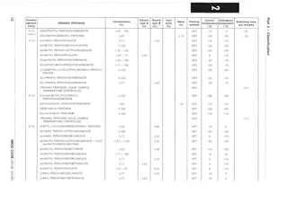
![:s:o
G>
o
o
o
m
i:
:3
~
CD
CD
6
~
01'0
(]I
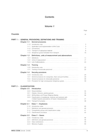
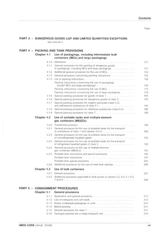
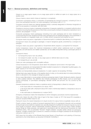
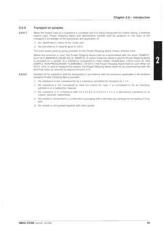
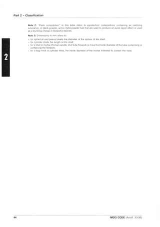
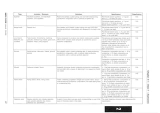
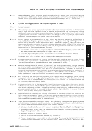
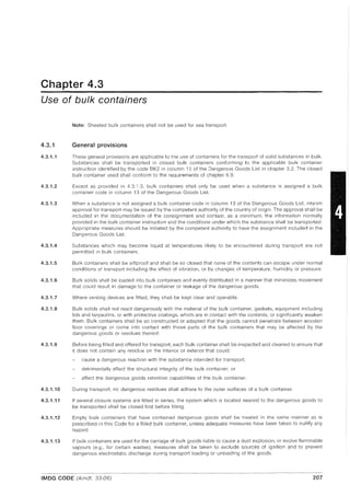
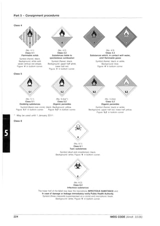
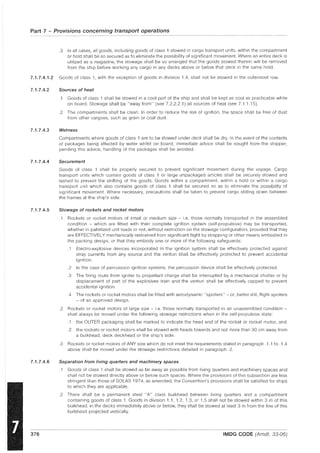
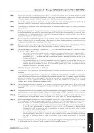
Type
Shell, spherical
or cylindrical
Includes: / Synonym:
Spherical display shell: aerial shell, colour
shell, dye shell, multi-break shell, multi-
effect shell, nautical shell, parachute shell,
smoke shell, star shell; report shell:
maroon, salute, sound shell, thunderclap,
aerial shell kit
Peanut shell
Preloaded mortar, shell in mortar
Shell of shells (spherical)
(Reference to percentages for shell of
shells are to the gross mass of the
fireworks article)
Definition
Device with or without propellant charge, with delay fuse and
bursting charge, pyrotechnic unit(s) or loose pyrotechnic
composition and designed to be projected from a mortar
Device with two or more spherical aerial shells in a common
wrapper propelled by the same propellant charge with separate
external delay fuses
Assembly comprising a spherical or cylindrical shell inside a
mortar from which the shell is designed to be projected
Device without propellant charge, with delay fuse and bursting
charge, containing report shells and inert materials and designed
to be projected from a mortar
Device without propellant charge, with delay fuse and bursting
charge, containing report shells ~ 25 g flash composition per
report unit, with ~ 33% flash composition and;:, 60% inert
materials and designed to be projected from a mortar
Device without propellant charge, with delay fuse and bursting
charge, containing colour shells and/or pyrotechnic units and
designed to be projected from a mortar
Device without propellant charge, with delay fuse and bursting
charge, containing colour shells ~ 70 mm and/or pyrotechnic
units, with ~ 25% flash composition and ~ 60% pyrotechnic
composition and designed to be projected from a mortar
Device with propellant charge, with delay fuse and bursting
charge, containing colour shells ~ 70 mm and/or pyrotechnic
units, with ~ 25% flash composition and ~ 60% pyrotechnic
composition and designed to be projected from a mortar
Specification Classification
All report shells 1.1G
Colour shell: ;:, 180 mm 1.1G
Colour shell: < 180 mm with> 25% flash 1.1G
composition, as loose powder and/or
report effects
Colour shell: < 180 mm with ~ 25% flash 1.3G
composition, as loose powder and/or
report effects
Colour shell: ~ 50 mm, or ~ 60 g 1.4G
pyrotechnic composition, with ~ 2% flash
composition as loose powder and/or
report effects
The most hazardous spherical aerial shell determines the
classification
All report shells 1.1G
Colour shell: ;:, 180 mm 1.1G
Colour shell: > 50 mm and < 180 mm 1.28
Colour shell: ~ 50 mm, or < 60 g 1.3G
pyrotechnic composition, with ~ 25%
flash composition as loose powder
and/or report effects
> 120 mm 1.1G
~ 120 mm 1.3G
> 300 mm 1.1G
> 200 mm and ~ 300 mm 1.3G
~ 200 mm 1.3G
(')
:r
OJ
-C
-CD
.....
IJ
......
(')
til
en
en
.....
I
~"'0
0-en
~.
en](https://image.slidesharecdn.com/imo-161102013454/85/Imo-imdg-1-2006-65-320.jpg)
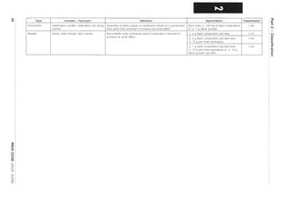

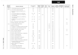
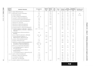
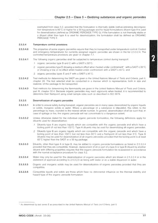

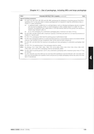
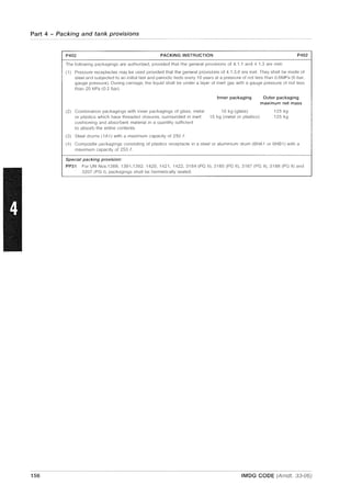
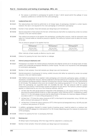
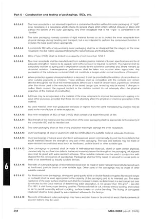
![Chapter 2.6 - Class 6 - Toxic and infectious substances
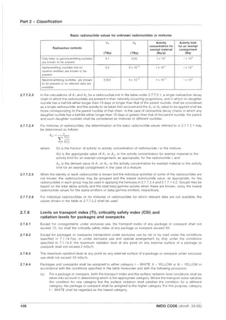
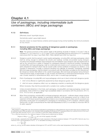
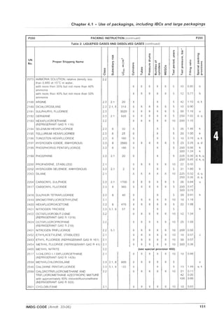
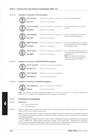
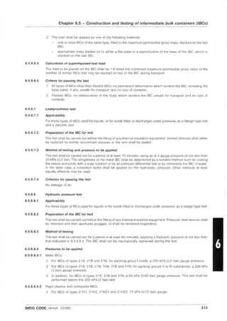
2.6.2.2.4.8 In the absence of LC50 data on the toxic constituent substances, the mixture may be assigned a packing
group based on the following simplified threshold toxicity tests. When these threshold tests are used, the most
restrictive packing group shall be determined and used for transporting the mixture.
2.6.2.3
2.6.2.3.1
2.6.2.3.2
2.6.2.3.3
.1 A mixture is assigned to packing group I only if it meets both of the following criteria:
- A sample of the liquid mixture is vaporized and diluted with air to create a test atmosphere of
1000 mUm
3
vaporized mixture in air. Ten albino rats (five male and five female) are exposed to the test
atmosphere for one hour and observed for 14 days. If five or more of the animals die within the 14-day
observation period, the mixture is presumed to have an LC50 equal to or less than 1000 mf/m3
- A sample of the vapour in equilibrium with the liquid mixture at 20"C is diluted with 9 equal volumes of
air to form a test atmosphere. Ten albino rats (five male and five female) are exposed to the test
atmosphere for one hour and observed for 14 days. If five or more of the animals die within the 14-day
observation period, the mixture is presumed to have a volatility equal to or greater than 10 times the
mixture LCso.
.2 A mixture is assigned to packing group II only if it meets both of the following criteria, and the mixture
does not meet the criteria for packing group I:
- A sample of the liquid mixture is vaporized and diluted with air to create a test atmosphere of
3000 mf/m3 vaporized mixture in air. Ten albino rats (five male and five female) are exposed to the test
atmosphere for one hour and observed for 14 days. If five or more of the animals die within the 14-day
observation period, the mixture is presumed to have an LCso equal to or less than 3000 mf/m3
- A sample of the vapour in equilibrium with the liquid mixture at 20"C is used to form a test atmosphere.
Ten albino rats (five male and five female) are exposed to the test atmosphere for one hour and
observed for 14 days. If five or more of the animals die within the 14 day observation period, the mixture
is presumed to have a volatility equal to or greater than the mixture LCso.
.3 A mixture is assigned to packing group III only if it meets both of the following criteria, and the mixture
does not meet the criteria for packing groups I or II:
A sample of the liquid mixture is vaporized and diluted with air to create a test atmosphere of
5000 mf/m3 vaporized mixture in air. Ten albino rats (five male and five female) are exposed to the test
atmosphere for one hour and observed for 14 days. If five or more of the animals die within the 14-day
observation period, the mixture is presumed to have an LCso equal to or less than 5000 mf/m]
- The vapour pressure of the liquid mixture is measured and if the vapour concentration is equal to or
greater than 1000 mf/m3, the mixture is presumed to have a volatility equal to or greater than ~ the
mixture LC50. .)
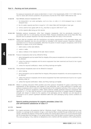
Methods for determining oral and dermal toxicity of mixtures
When classifying and assigning the appropriate packing group to mixtures in class 6.1, in accordance with the
oral and dermal toxicity criteria in 2.6.2.2, it is necessary to determine the acute LDso of the mixture.
If a mixture contains only one active substance, and the LDso of that constituent is known, in the absence of
reliable acute oral and dermal toxicity data on the actual mixture to be transported, the oral or dermal LD50
may be obtained by the following method:
LD'iO value of active substance x 100
LD50 value of preparation = ---'.-"-----:-----------,-----
percentage of active substance by mass
If a mixture contains more than one active constituent, there are three possible approaches that may be used
to determine the oral or dermal LD50 of the mixture. The preferred method is to obtain reliable acute oral and
dermal toxicity data on the actual mixture to be transported. If reliable, accurate data are not available, then
either of the following methods may be performed:
.1 Classify the formulation according to the most hazardous constituent of the mixture as if that constituent
were present in the same concentration as the total concentration of all active constituents; or
.2 Apply the formula:
where: C = the % concentration of constituent A, B ... Z in the mixture;
T = the oral LDso value of constituent A, B ... Z;
TM = the oral LD50 value of the mixture.
IMDG CODE (Amdt. 33-06) 81](https://image.slidesharecdn.com/imo-161102013454/85/Imo-imdg-1-2006-101-320.jpg)


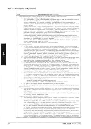
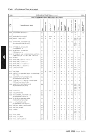
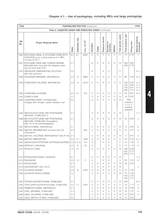

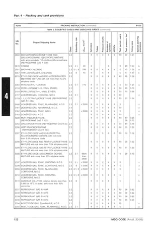
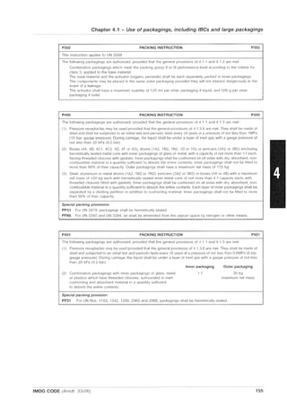

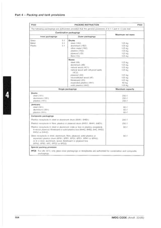


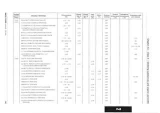
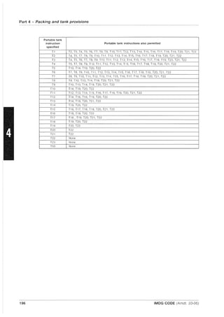
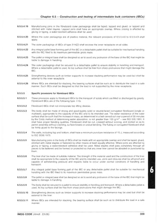
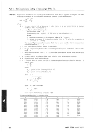
![Part 4 - Packing and tank provisions
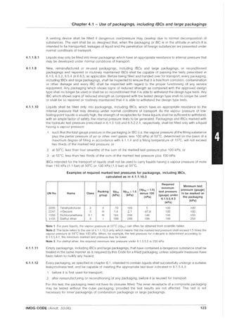
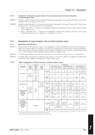
4.2.1.14
4.2.1.15
Additional provisions applicable to the transport of class 6.1 substances in portable tanks
[Reserved]
Additional provisions applicable to the transport of class 6.2 substances in portable tanks
[Reserved]
4.2.1.16 Additional provisions applicable to the transport of class 7 substances in portable tanks
4.2.1.16.1 Portable tanks used for the transport of radioactive material shall not be used for the transport of other goods.
4.2.1.16.2 The degree of filling for portable tanks shall not exceed 90% or, alternatively, any other value approved by the
competent authority.
4.2.1.17 Additional provisions applicable to the transport of class 8 substances in portable tanks
4.2.1.17.1 Pressure-relief devices of portable tanks used for the transport of class 8 substances shall be inspected at
intervals not exceeding one year.
4.2.1.18 Additional provisions applicable to the transport of class 9 substances in portable tanks
[Reserved]
4.2.1.19 Additional provisions applicable to the transport of solid substances
transported above their melting point
4.2.1.19.1 Solid substances transported or offered for transport above their melting point which are not assigned a
portable tank instruction in column (13) of the Dangerous Goods List of chapter 3.2 or when the assigned
portable tank instruction does not apply to transport at temperatures above their melting point may be
transported in portable tanks provided that the solid substances are classified in classes 4.1,4.2,4.3, 5.1,6.1,
8 or 9 and have no subsidiary risk other than that of class 6.1 or class 8 and are in packing group II or III.
4.2.1.19.2 Unless otherwise indicated in the Dangerous Goods List, portable tanks used for the transport of these solid
substances above their melting point shall conform to the provisions of portable tank instruction T4 for solid
substances of packing group III or T7 for solid substances of packing group II. A portable tank that affords an
equivalent or greater level of safety may be selected in accordance with 4.2.5.2.5. The maximum degree of
filling (in %) shall be determined according to 4.2.1.9.5 (TP3).
4.2.2 General provisions for the use of portable tanks for the transport
of non-refrigerated liquefied gases
4.2.2.1 This section provides general provisions applicable to the use of portable tanks for the transport of non-
refrigerated liquefied gases of class 2.
4.2.2.2 Portable tanks shall conform to the deSign, construction, inspection and testing provisions detailed in 6.7.3.
Non-refrigerated liquefied gases shall be transported in portable tanks conforming to portable tank instruction
T50 as described in 4.2.5.2.6 and any portable tank special provisions assigned to specific non-refrigerated
liquefied gases in the Dangerous Goods List and described in 4.2.5.3.
4.2.2.3 During transport, portable tanks shall be adequately protected against damage to the shell and service
equipment resulting from lateral and longitudinal impact and overturning. If the shell and service equipment
are so constructed as to withstand impact or overturning, it need not be protected in this way. Examples of
such protection are given in 6.7.3.13.5.
4.2.2.4 Certain non-refrigerated liquefied gases are chemically unstable. They are accepted for transport only when
the necessary steps have been taken to prevent their dangerous decomposition, transformation or
polymerization during transport. To this end, care shall be taken to ensure that portable tanks do not
contain any non-refrigerated liquefied gases liable to promote these reactions.
4.2.2.5 Unless the name of the gas(es) being transported appears on the metal plate described in 6.7.3.16.2, a copy
of the certificate specified in 6.7.3.14.1 shall be made available upon a competent authority request and
readily provided by the consignor, consignee or agent, as appropriate.
4.2.2.6 Empty portable tanks not cleaned and not gas-free shall comply with the same provisions as portable tanks
filled with the previous non-refrigerated liquefied gas.
192 IMDG CODE (Amdt. 33-06)](https://image.slidesharecdn.com/imo-161102013454/85/Imo-imdg-1-2006-208-320.jpg)


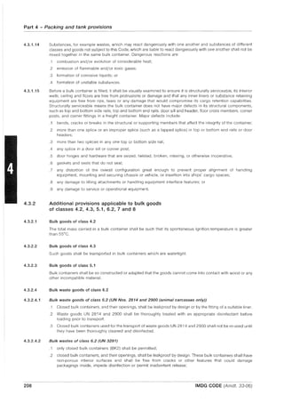


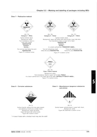
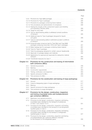
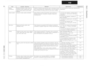
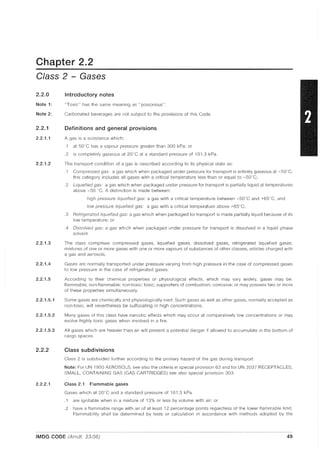
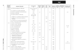
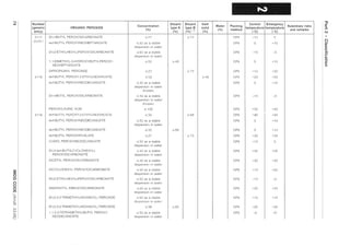
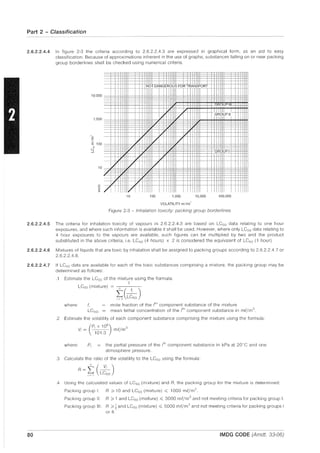
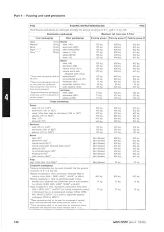
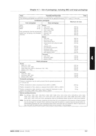
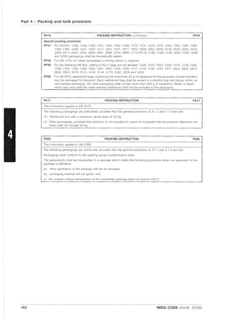
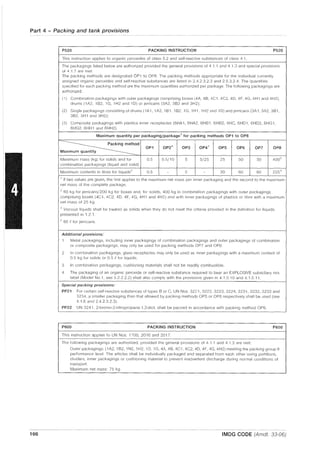
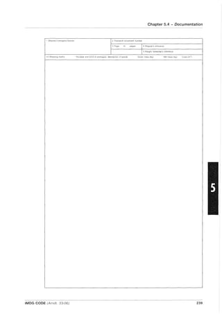
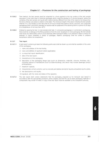
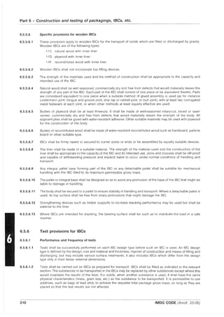
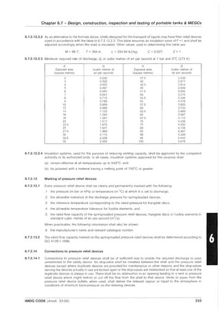
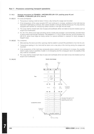
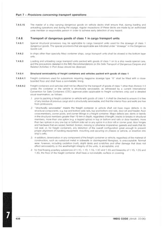
![Chapter 5.4 - Documentation
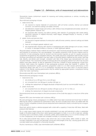
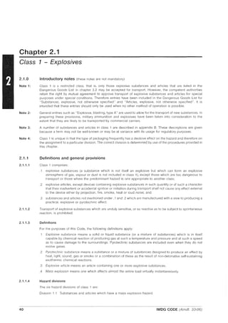
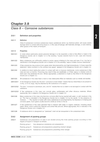
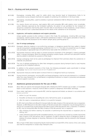
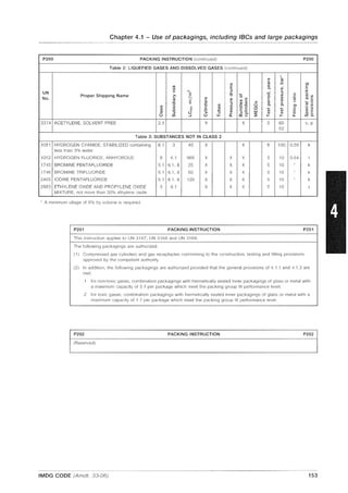
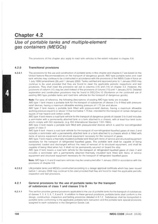
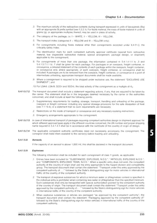
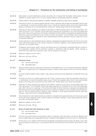
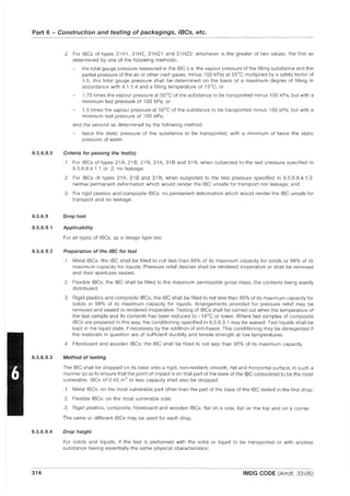
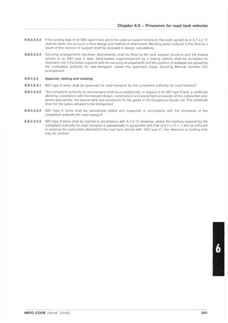
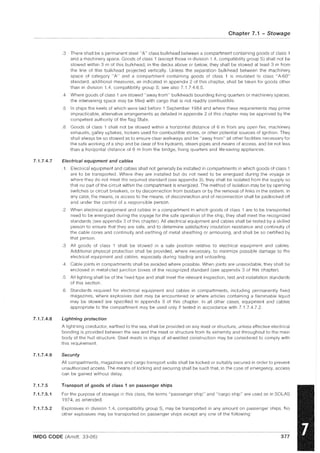
MULTIMODAL DANGEROUS GOODS FORM
This form may be used as a dangerous goods declaration as it meets the requirements of SOlAS 74, chapter
VII, regulation 4; MARPOl 73/78, Annex III, regulation 4.
1 Shipper/Consignor/Sender 2 Transport document number
3 Page 1 of pages 4 Shipper's reference
5 Freight forwarder's reference
6 Consignee 7 Carrier Ito be completed by the cmrier)
SHIPPER'S DECLARATION
hereby declare that ttle contents of this consignment are fully and
below by the Proper Shipping Name, and are classified, packaged,
placarded and in all respects in proper condition for transport according . applicable
international national governmental regulations
8 This shipment the limitations prescnbed for 9 Additional handling Information
(Delete
PASSENGER AND CARGO CARGO AIRCRAFT
AIRCRAFT ONLY
10 Vessel/flight No. and date 11 POIt/place of loading
12 Port/place of discharge 13 Destination
14 Shipping marks ' Number and kind of packages; description of goods Gross mass (kg) Net mass (k,]) Cube (m:l)
15 Container No./ 16 Seal number(s)
vehicle registratiOi No.
CONTAINER/VEHICLE PACKING CERTIFICATE
I hereby declare Ihat the goods described above have been
packed/loaded into the container/vehicle identified above In
accordance with the applicable provislons.·I
·
MUST BE COMPLETED AND SIGNED FOR ALL CONTAINER/
VEHICLE LOADS BY PERSON RESPONSIBLE FOR PACKING/
LOADING
20 Name of company
Name/status of declarant
Place and date
Signature of declarant
DANGEROUS GOODS:
You must specify: UN No.,
under applicable national
For the purposes of the IMDG Code, see 5.4.2
IMDG CODE (Amdt. 33-06)
17 Container/vehicle size & 18 Tare mass 19 Total gross mass (inclL.-ding tare)
type (kg) (kg)
21 RECEIVING ORGANISATION RECEIPT
the above number of packages/containers/trailers in apr~arent good order and
unless stated hereon: RECEIVING ORGANIS"TION REMARKS:
Haulier's name 22 Name of company (OF SHIPPER
PREPARING THIS NOTE)
Vehicle reg. no.
Signature and dale
Name/status of declarant
Place and dale
DRIVER·S SIGNATUI'iE Signature of declarant
observe the mandatory requlremenls
237](https://image.slidesharecdn.com/imo-161102013454/85/Imo-imdg-1-2006-251-320.jpg)


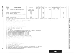
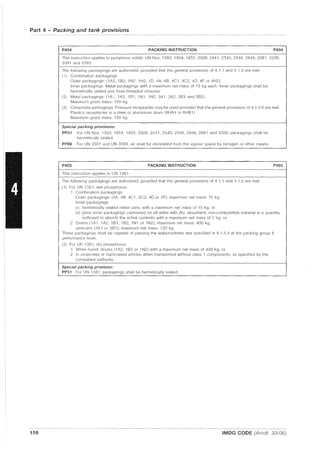
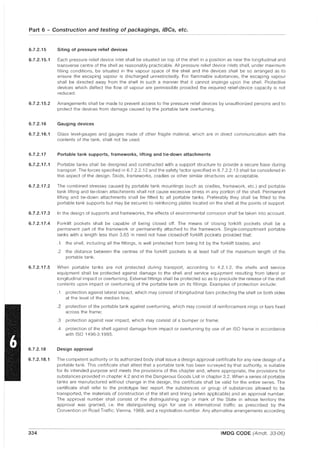
![Chapter 6.4
Provisions for the construction, testing and approval
of packages and material of class 7
Note:
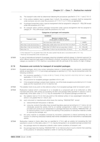
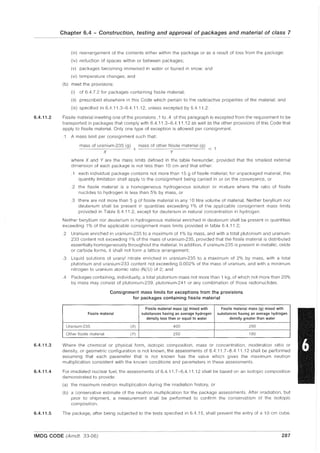
6.4.1
6.4.2
6.4.2.1
6.4.2.2
6.4.2.3
6.4.2.4
6.4.2.5
6.4.2.6
6.4.2.7
6.4.2.8
6.4.2.9
6.4.2.10
6.4.2.11
6.4.2.12
This chapter includes provisions which apply to the construction, testing and approval of certain packages
and material only when transported by air. Whilst these provisions do not apply to packages/material
transported by sea, the provisions are reproduced for information/identification purposes, since such
packages/material, designed, tested and approved for air transport, may also be transported by sea.
[reserved]
General provisions
The package shall be so designed in relation to its mass, volume and shape that it can be easily and safely
transported In addition, the package shall be so designed that it can be properly secured in or on the
conveyance during transport.
The design shall be such that any lifting attachments on the package will not fail when used in the intended
manner and that, if failure of the attachments shall occur, the ability of the package to meet other provisions of
this Code would not be impaired. The design shall take account of appropriate safety factors to cover snatch
lifting.
Attachments and any other features on the outer surface of the package which could be used to lift it shall be
designed either to support its mass in accordance with the provisions of 6.4.2.2 or shall be removable or
otherwise rendered incapable of being used during transport.
As far as practicable, the packaging shall be so designed and finished that the external surfaces are free from
protruding features and can be easily decontaminated.
As far as practicable, the outer layer of the package shall be so designed as to prevent the collection and the
retention of water.
Any features added to the package at the time of transport which are not part of the package shall not reduce
its safety.
The package shall be capable of withstanding the effects of any acceleration, vibration or vibration resonance
which may arise under routine conditions of transport without any deterioration in the effectiveness of the
closing devices on the various receptacles or in the integrity of the package as a whole. In particular, nuts,
bolts and other securing devices shall be so designed as to prevent them from becoming loose or being
released unintentionally, even after repeated use.
The materials of the packaging and any components or structures shall be physically and chemically
compatible with each other and with the radioactive contents. Account shall be taken of their behaviour under
irradiation.
All valves through which the radioactive contents could otherwise escape shall be protected against
unauthorized operation.
The design of the package shall take into account ambient temperatures and pressures that are likely to be
encountered in routine conditions of transport.
For radioactive material having other dangerous properties, the package design shall take into account those
properties; see 4.1.9.1.5, 2.0.3.1 and 2.03.2.
Manufacturers and subsequent distributors of packagings shall provide information regarding procedures to
be followed and a description of the types and dimensions of closures (including required gaskets) and any
other components needed to ensure that packages as presented for transport are capable of passing the
applicable performance tests of this chapter.
IMDG CODE (Amdt. 33-06) 281](https://image.slidesharecdn.com/imo-161102013454/85/Imo-imdg-1-2006-295-320.jpg)


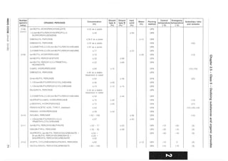
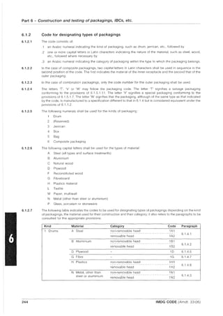
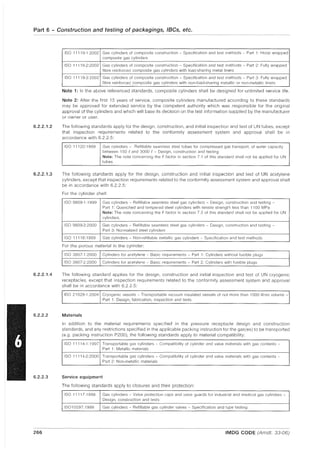
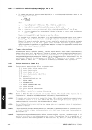
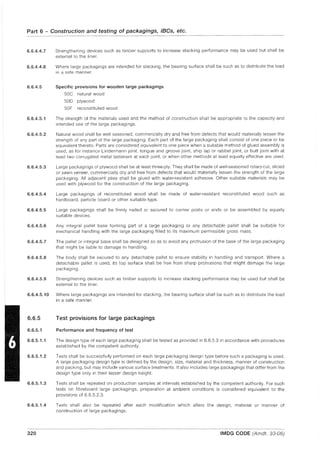
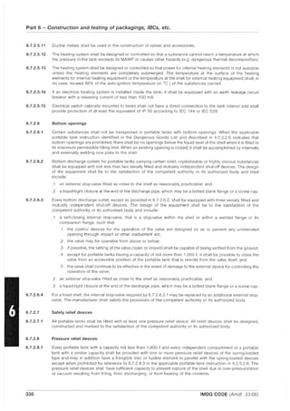
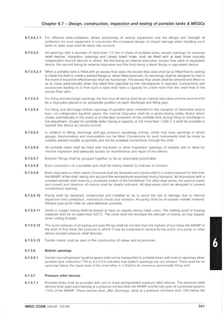
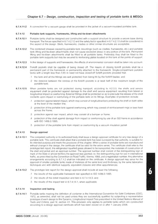
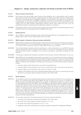
![Part 6 - Construction and testing of packagings, IBCs, etc.
6.4.20.2
6.4.20.3
6.4.20.4
6.4.21
6.4.22
6.4.22.1
6.4.22.2
6.4.22.3
6.4.22.4
6.4.22.5
6.4.23
6.4.23.1
6.4.23.2
292
Puncture/tearing test: The specimen shall be subjected to the damaging effects of a solid probe made of mild
steel. The orientation of the probe to the surface of the specimen shall be as to cause maximum damage at the
conclusion of the test sequence specified in 6.4.20.1 (a).
(a) The specimen. representing a package having a mass less than 250 kg, shall be placed on a target and
subjected to a probe having a mass of 250 kg falling from a height of 3 m above the intended impact
point. For this test. the probe shall be a 20 cm diameter cylindrical bar with the striking end forming a
frustum of a right circular cone with the following dimensions: 30 cm height and 2.5 em in diameter at the
top with its edge rounded off to a radius of not more than 6 mm. The target on which the specimen is
placed shall be as specified in 6.4.14.
(b) For packages having a mass of 250 kg or more. the base of the probe shall be placed on a target and the
specimen dropped onto the probe. The height of the drop. measured from the point of impact with the
specimen to the upper surface of the probe, shall be 3 m. For this test, the probe shall have the same
properties and dimensions as specified in (a) above, except that the length and mass of the probe shall be
such as to incur maximum damage to the specimen. The target on which the base of the probe is placed
shall be as specified in 6.4.14.
Enhanced thermal test: The conditions for this test shall be as specified in 6.4.17.3, except that the exposure
to the thermal environment shall be for a period of 60 minutes.
Impact test: The specimen shall be subject to an impact on a target at a velocity of not less than 90 mis, at
such an orientation as to suffer maximum damage. The target shall be as defined in 6.4.14, except that the
target surface may be at any orientation provided that the surface is normal to the specimen path.
Tests for packagings designed to contain uranium hexafluoride
Specimens that comprise or simulate packagings designed to contain 0.1 kg or more of uranium hexafluoride
shall be tested hydraulically at an internal pressure of at least 1.38 MPa but, when the test pressure is less than
2.76 MPa, the design will require multilateral approval. For retesting packagings, any other equivalent non-
destructive testing may be applied, subject to multilateral approval.
Approvals of package designs and materials
The approval of designs for packages containing 0.1 kg or more of uranium hexafluoride requires that:
(a) Each design that meets the provisions of 6.4.6.4 shall require multilateral approval;
(b) Each design that meets the provisions of 6.4.6.1 to 6.4.6.3 shall require unilateral approval by the
competent authority of the country of origin of the design, unless multilateral approval is otherwise
required by th is Code.
Each Type 8(U) and Type C package design will require unilateral approval, except that:
(a) a package design for fissile material which is also subject to 6.4.22.4, 6.4.23.7 and 5.1.5.3.1 will require
multilateral approval; and
(b) a Type 8(U) package design for low dispersible radioactive material will require multilateral approval.
Each Type 8(M) package design, including those for fissile material which are also subject to 6.4.22.4,
6.4.23.7 and 5.1.5.3.1 and those for low dispersible radioactive material, will require multilateral approval.
Each package design for fissile material which is not excepted according to 6.4.11.2 from the provisions that
apply specifically to packages containing fissile material will require multilateral approval.
The design for special form radioactive material will require unilateral approval. The design for low dispersible
radioactive material will require multilateral approval (see also 6.4.23.8).
Applications for approval and approvals for radioactive material transport
[reserved]
An application for shipment approval shall include:
(a) the period of time, related to the shipment, for which the approval is sought;
(b) the actual radioactive contents, the expected modes of transport, the type of conveyance, and the
probable or proposed route; and
(c) the details of how the precautions and administrative or operational controls referred to in the package
design approval certificates issued under 5.1.5.3.1 are to be put into effect.
IMDG CODE (Amdt. 33-06)](https://image.slidesharecdn.com/imo-161102013454/85/Imo-imdg-1-2006-306-320.jpg)


![Handling of dangerous goods [compatibility mode]](https://cdn.slidesharecdn.com/ss_thumbnails/handlingofdangerousgoodscompatibilitymode-180629075613-thumbnail.jpg?width=640&height=640&fit=bounds)


![Sæter day 2 8_foredrag[1]](https://cdn.slidesharecdn.com/ss_thumbnails/sterday28foredrag1-120502022810-phpapp02-thumbnail.jpg?width=640&height=640&fit=bounds)
![Sæter day 2 8_foredrag[1]](https://cdn.slidesharecdn.com/ss_thumbnails/sterday28foredrag1-120502025329-phpapp02-thumbnail.jpg?width=640&height=640&fit=bounds)


