This document provides an overview of safety and security topics related to basic industrial wiring. It discusses the physiological effects of electricity on the human body, including how electric current can cause heating, damage nerves and tissues. Threshold values for electric sensation, the ability for a person to let go, and ventricular fibrillation are defined. The main causes of electric shocks are also examined, such as inappropriate operating modes, lack of awareness of risks, and inadequate training. Formulas are provided to calculate body impedance and the current that will flow through the body depending on voltage exposure. The various effects of electric current on the body are also summarized.
![[Didactic Equipment]
[Industrial
Automation
– Part 1
Installation]
[Safety and Security –
Basic Industrial wiring]
Eric Dupont](https://image.slidesharecdn.com/iaindustrialautomation-part1-210930233627/75/Ia-industrial-automation-part-1-1-2048.jpg)
![V1.1 – Confidential Property of CoE EARE
2 [Industrial Automation – Part 1 Installation] [Safety and Security – Basic Industrial wiring]](https://image.slidesharecdn.com/iaindustrialautomation-part1-210930233627/75/Ia-industrial-automation-part-1-2-2048.jpg)
![V1.1 – Confidential Property of CoE EARE
2 [Industrial Automation – Part 1 Installation] [Safety and Security – Basic Industrial wiring]](https://image.slidesharecdn.com/iaindustrialautomation-part1-210930233627/75/Ia-industrial-automation-part-1-4-2048.jpg)

![V1.1 – Confidential Property of CoE EARE
4 [Industrial Automation – Part 1 Installation] [Safety and Security – Basic Industrial wiring]
Safety & Security
In this section the topics will be the effect of the electricity on the human Body, the way to
prevent electric shock, the equipment used to protect people.](https://image.slidesharecdn.com/iaindustrialautomation-part1-210930233627/75/Ia-industrial-automation-part-1-6-2048.jpg)
![V1.1 – Confidential Property of CoE EARE
6 [Industrial Automation – Part 1 Installation] [Safety and Security – Basic Industrial wiring]
1- PREAMBLE:
As electric current is conducted through a material, any opposition to that flow of electrons
(resistance) results in a dissipation of energy, usually in the form of heat. This is the most
basic and easy-to-understand effect of electricity on living tissue: current makes it heat up. If
the amount of heat generated is sufficient, the tissue may be burnt. The effect is
physiologically the same as damage caused by an open flame or other high-temperature
source of heat, except that electricity has the ability to burn tissue well beneath the skin of a
victim, even burning internal organs.
Another effect of electric current on the body, perhaps the most significant in terms of
hazard, regards the nervous system. By "nervous system" I mean the network of special cells
in the body called "nerve cells" or "neurons" which process and conduct the multitude of
signals responsible for regulation of many body functions. The brain, spinal cord, and
sensory/motor organs in the body function together to allow it to sense, move, respond, think,
and remember.
2- DEFINITIONS
Internal impedance of the human body (Z1): Impedance between two electrodes in
contact with two parts of the human body, after removing the skin from under the
electrodes.
Impedance of the skin (Zp): Impedance between an electrode on the skin and the
conductive tissues underneath.
Total impedance of the human body (ZT): Vectorial sum of the internal impedance
and the impedances of the skin.
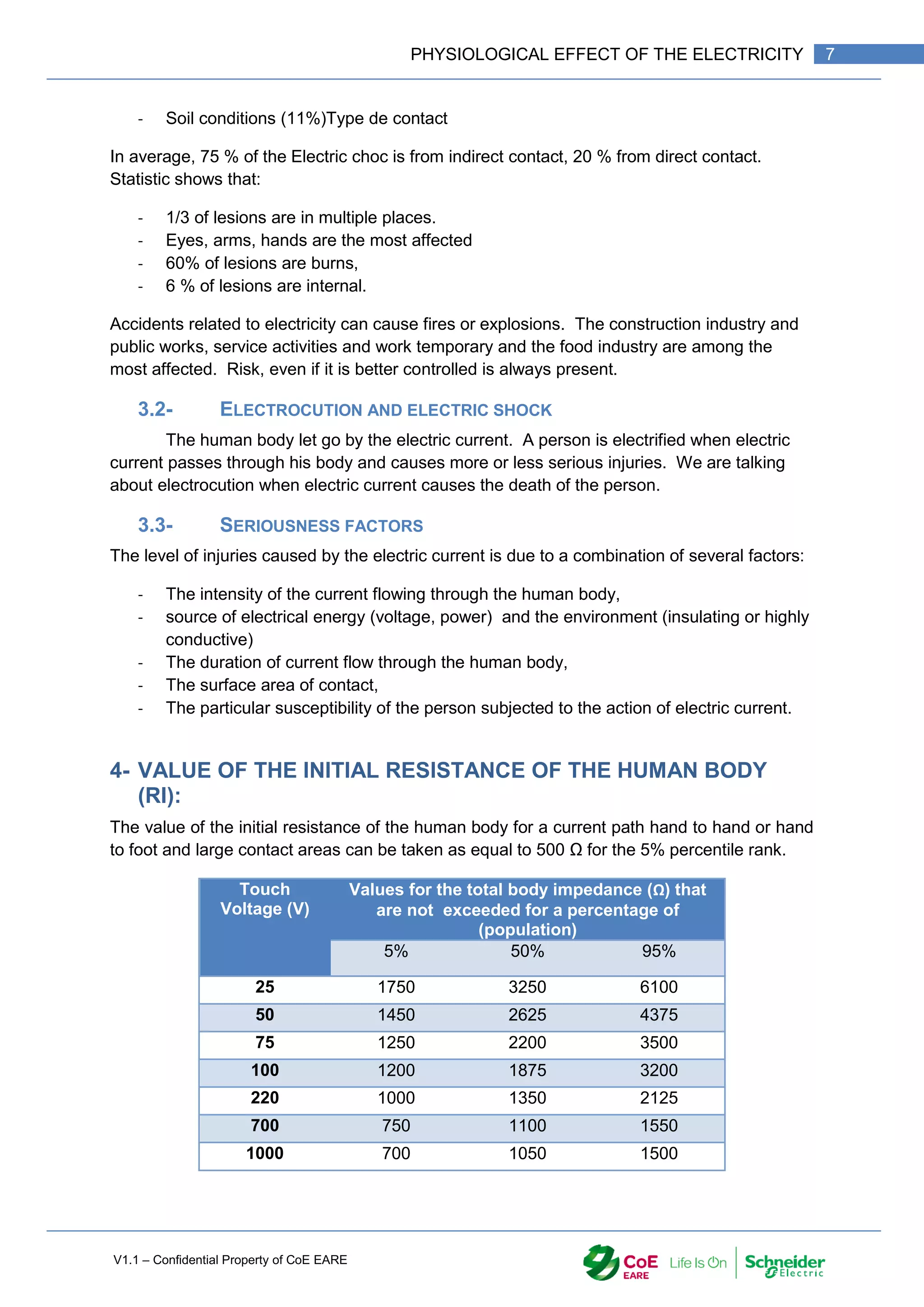
Initial resistance of the human body (Ri): Resistance limiting the peak value of the
current at the moment when the touch voltage occurs.
Threshold of perception: The minimum value of current which causes any
sensation for the person through which it is flowing.
Threshold of let-go: The maximum value of current at which a person holding
electrodes can let go of the electrodes.
Threshold of ventricular fibrillation: The minimum value of current which causes
ventricular fibrillation.
Heart current factor: The heart current factor relates the electric field strength in the
heart for a given current path to the electric field strength in the heart for a current of
equal magnitude flowing from left hand to feet. Note. - In the heart, the current density
is proportional to the electric field strength.
3- MAIN CAUSES OF ELECTRIC CHOCKS
3.1- MAIN CAUSES ARE:
- Operating mode inappropriate or dangerous (31%),
- Lack of awareness of risks (30%),
- Incomplete application procedures (15%),
- Inadequate training (12%),
- The state of the material (12%),](https://image.slidesharecdn.com/iaindustrialautomation-part1-210930233627/75/Ia-industrial-automation-part-1-8-2048.jpg)
![V1.1 – Confidential Property of CoE EARE
8 [Industrial Automation – Part 1 Installation] [Safety and Security – Basic Industrial wiring]
The internal impedance of the human body is a function of the current path.
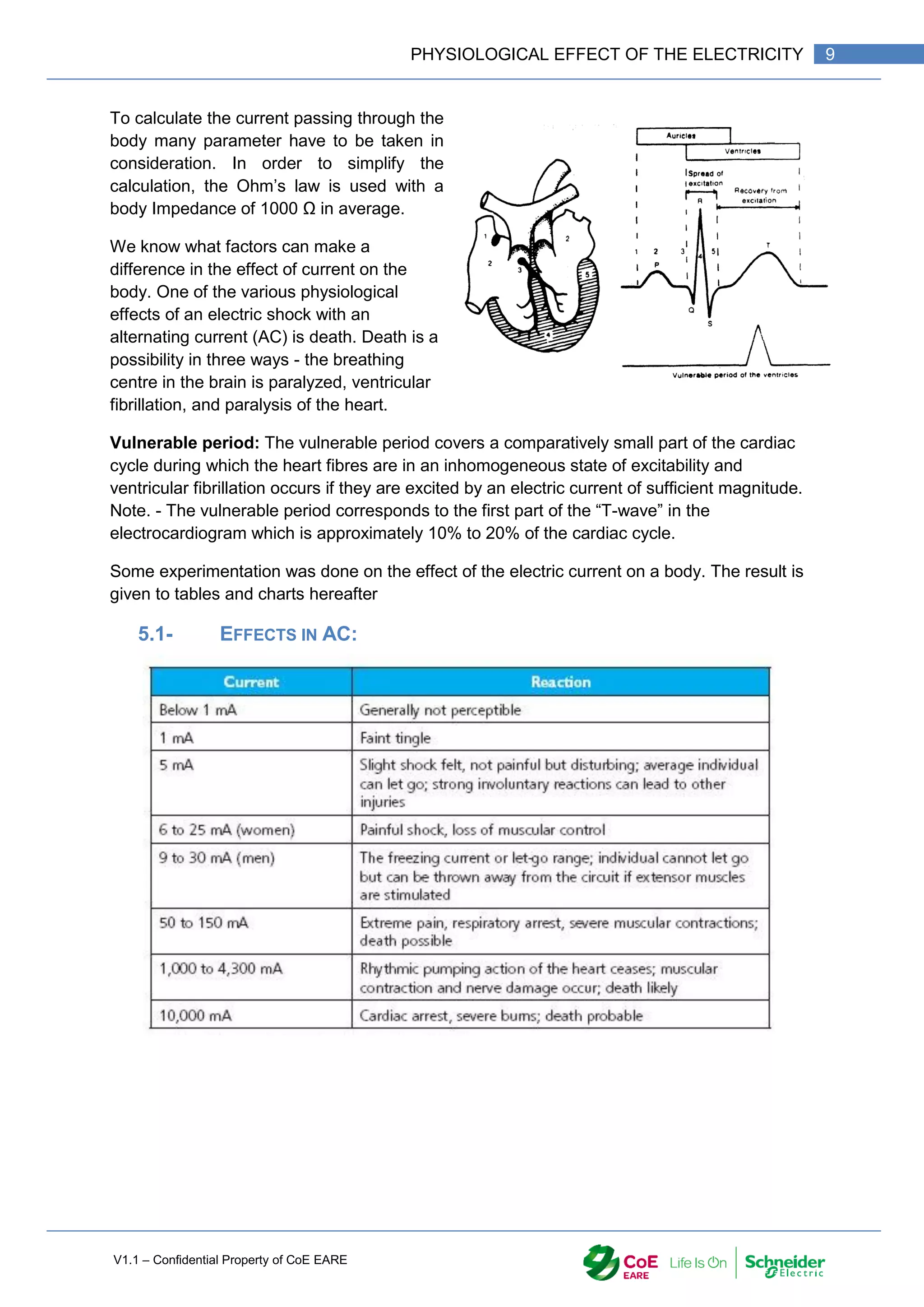
5- CURRENT THROUGH THE BODY AND EFFECTS
The effect of the current in a body can take several forms.
- Thermic effect – Burns (can be done with 10 mA if the contact takes few minutes.
- Tetanizing Effects – When an AC current is going through the body, muscles are
contracted.](https://image.slidesharecdn.com/iaindustrialautomation-part1-210930233627/75/Ia-industrial-automation-part-1-10-2048.jpg)
![V1.1 – Confidential Property of CoE EARE
10 [Industrial Automation – Part 1 Installation] [Safety and Security – Basic Industrial wiring]](https://image.slidesharecdn.com/iaindustrialautomation-part1-210930233627/75/Ia-industrial-automation-part-1-12-2048.jpg)
![V1.1 – Confidential Property of CoE EARE
12 [Industrial Automation – Part 1 Installation] [Safety and Security – Basic Industrial wiring]
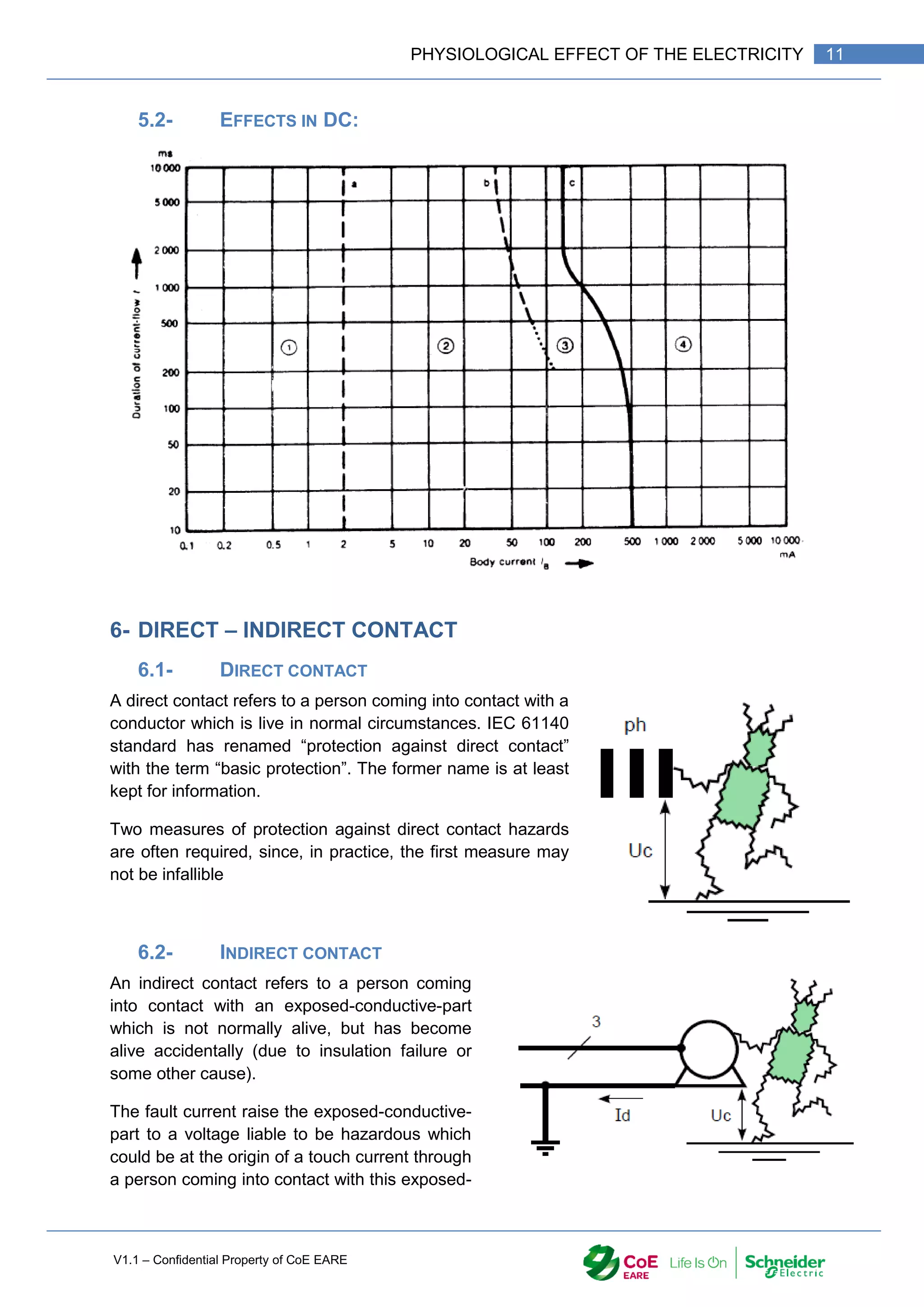
conductive-part see. IEC 61140 standard has renamed “protection against indirect contact”
with the term “fault protection”. The former name is at least kept for information.
7- FIRST AID
The danger from an electrical shock depends on the type of current, how high the voltage is,
how the current travelled through the body, the person's overall health and how quickly the
person is treated.
Call your local emergency number immediately if any of these signs or symptoms
occurs:
Cardiac arrest
Heart rhythm problems (arrhythmias)
Respiratory failure
Muscle pain and contractions
Burns
Seizures
Numbness and tingling
Unconsciousness
While waiting for medical help, follow these steps:
Look first. Don't touch. The person may still be in contact with the electrical source.
Touching the person may pass the current through you.
Turn off the source of electricity, if possible. If not, move the source away from you
and the person, using a dry, no-conducting object made of cardboard, plastic or
wood.
Check for signs of circulation (breathing, coughing or movement). If absent, begin
cardiopulmonary resuscitation (CPR) immediately.
Prevent shock. Lay the person down and, if possible, position the head slightly lower
than the trunk with the legs elevated.
After coming into contact with electricity, the person should see a doctor to check for internal
injuries, even if he or she has no obvious signs or symptoms.
Caution
Don't touch the person with your bare hands if he or she is still in contact with the
electrical current.
Don't get near high-voltage wires until the power is turned off. Stay at least 20 feet
away — farther if wires are jumping and sparking.
Don't move a person with an electrical injury unless the person is in immediate
danger.](https://image.slidesharecdn.com/iaindustrialautomation-part1-210930233627/75/Ia-industrial-automation-part-1-14-2048.jpg)

![V1.1 – Confidential Property of CoE EARE
14 [Industrial Automation – Part 1 Installation] [Safety and Security – Basic Industrial wiring]
1- INTRODUCTION
The security in electrical work is one of the most important part of the work. By nature
electricity is dangerous and all actions have to be taken to prevent electric hazards and
protect people against Direct and Indirect chocks.
2- PREVENT DIRECT CONTACTS:
When it is not possible to shut down the power or lock a switch
disconnector, live accessible part to workers must be ensured
by:
- Remoteness,
- Obstacles
- Insulation.
2.1- REMOTENESS
Remoteness is to provide enough distance between live parts and worker that a contact
won’t be possible with conducting object. (metallic pipe, …)
2.2- OBSTACLES
The insulation between people and live part is
provided by putting in place obstacles when the
remoteness is not possible. The obstacles can be
cabinets, boxes … protecting people against direct
contact.
2.3- INSULATION
Insulation consist in cover live part with insulated
material such as insulated mat … This is required
when the remoteness and obstacle procedure can't be
put in place.](https://image.slidesharecdn.com/iaindustrialautomation-part1-210930233627/75/Ia-industrial-automation-part-1-16-2048.jpg)
![V1.1 – Confidential Property of CoE EARE
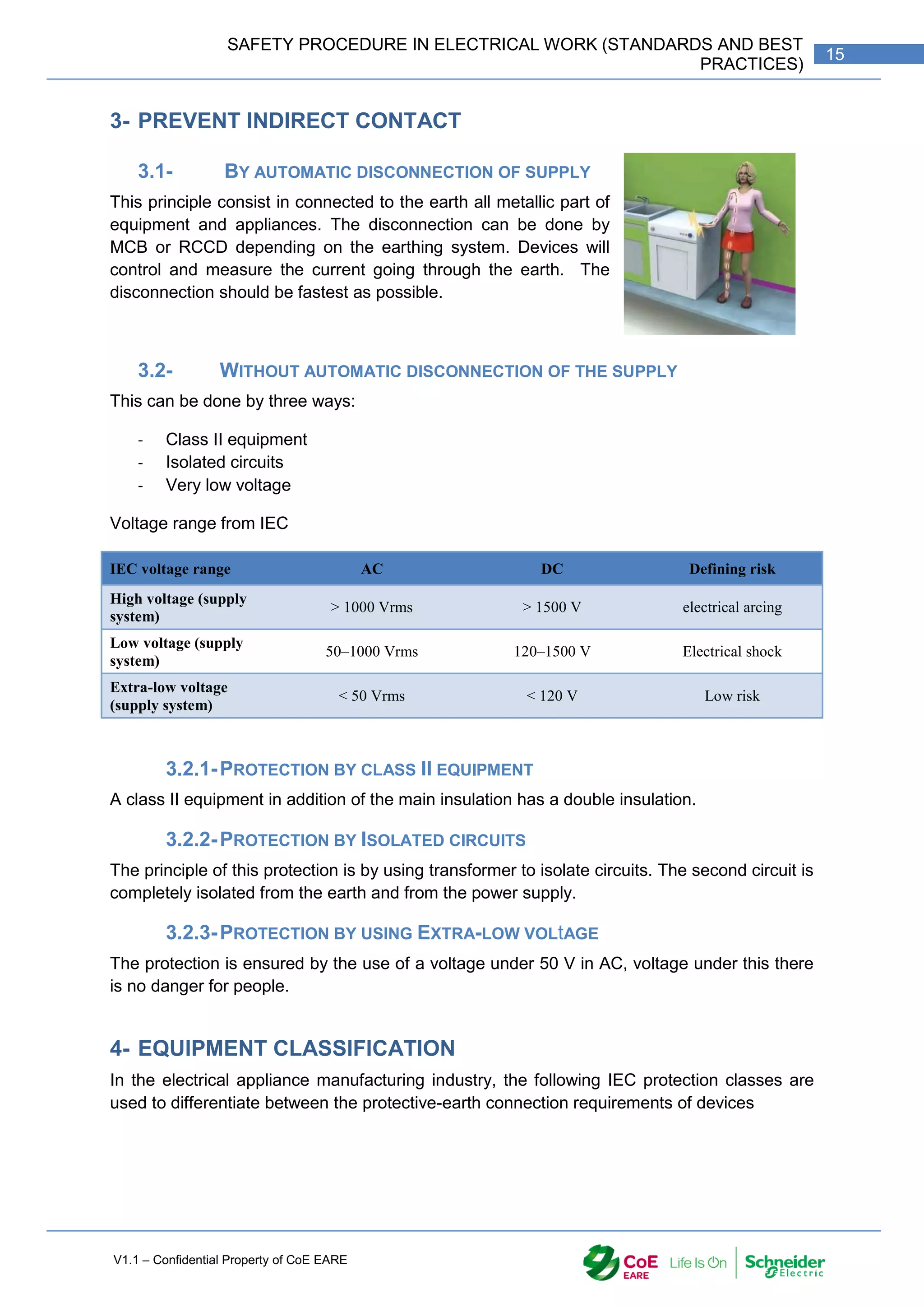
16 [Industrial Automation – Part 1 Installation] [Safety and Security – Basic Industrial wiring]
4.1- CLASS 0
These appliances have no protective-earth connection and feature only a single level of
insulation and were intended for use in dry areas. A single fault could cause an electric shock
or other dangerous occurrence. Theses appliances are forbidden.
4.2- CLASS 1
These appliances must have their chassis connected to electrical earth (ground)
by a separate earth conductor (coloured green - green/yellow in most countries).
The earth connection is achieved with a 3-conductor mains cable, typically ending
with 3-prong AC connector which plugs into a corresponding AC outlet. The basic
requirement is that no single failure can result in dangerous voltage becoming exposed so
that it might cause an electric shock and that if a fault occurs the supply will be removed
automatically.
A fault in the appliance which causes a live conductor to contact the casing will cause a
current to flow in the earth conductor. If large enough, this current will trip an over-current
device (fuse or circuit breaker (CB)) and disconnect the supply.
4.3- CLASS 2
A Class II or double insulated electrical appliance is one which has been designed
in such a way that it does not require a safety connection to electrical earth
(ground). The basic requirement is that no single failure can result in dangerous
voltage becoming exposed so that it might cause an electric shock and that this is
achieved without relying on an earthed metal casing. This is usually achieved at least in part
by having two layers of insulating material surrounding live parts or by using reinforced
insulation.
4.4- CLASS 3
A Class III appliance is designed to be supplied from a separated/safety extra-low
voltage (SELV) power source. The voltage from a SELV supply is low enough that
under normal conditions a person can safely come into contact with it without risk of
electrical shock. For medical devices, compliance with Class III is not considered sufficient
protection, and further more-stringent regulations apply to such equipment.
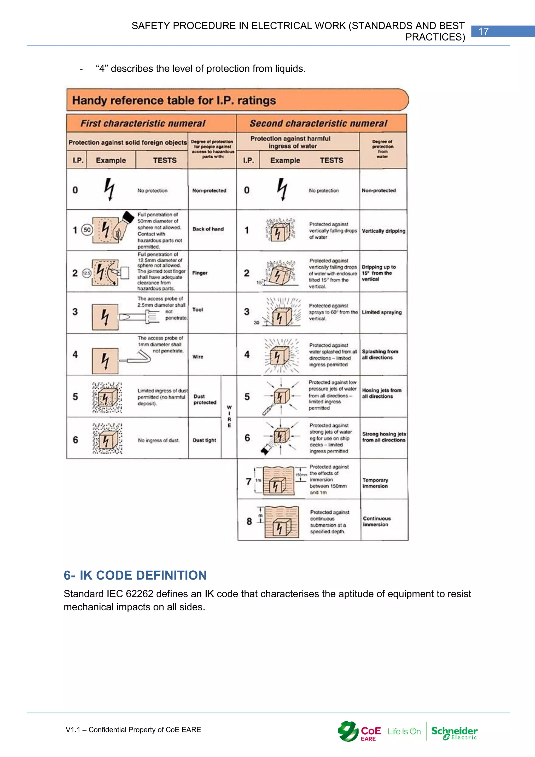
5- IP CODE
The IP Code, International Protection Marking (IEC 60529), classifies and rates the degree of
protection provided against the intrusion (including body parts such as hands and fingers),
dust, accidental contact, and water by mechanical casings and electrical enclosures.
The standard aims to provide users more detailed information than vague marketing terms
such as waterproof. The digits (characteristic numerals) indicate conformity with the
conditions summarized in the tables below. Where there is no protection rating with regard to
one of the criteria, the digit is replaced with the letter X.
With the IP rating IP 54
- “5” describes the level of protection from solid objects](https://image.slidesharecdn.com/iaindustrialautomation-part1-210930233627/75/Ia-industrial-automation-part-1-18-2048.jpg)
![V1.1 – Confidential Property of CoE EARE
18 [Industrial Automation – Part 1 Installation] [Safety and Security – Basic Industrial wiring]
7- OVERVOLTAGE CATEGORIES
Measurement category is classification of live electric circuits is used in measurement and
testing of installations and equipment, usually in the relation within a building (residential or
industrial).
The categories take into account the total continuous energy available at the given point of
circuit, and the occurrence of impulse voltages. The energy can be limited by circuit breakers
or fuses, and the impulse voltages by the nominal level of voltage
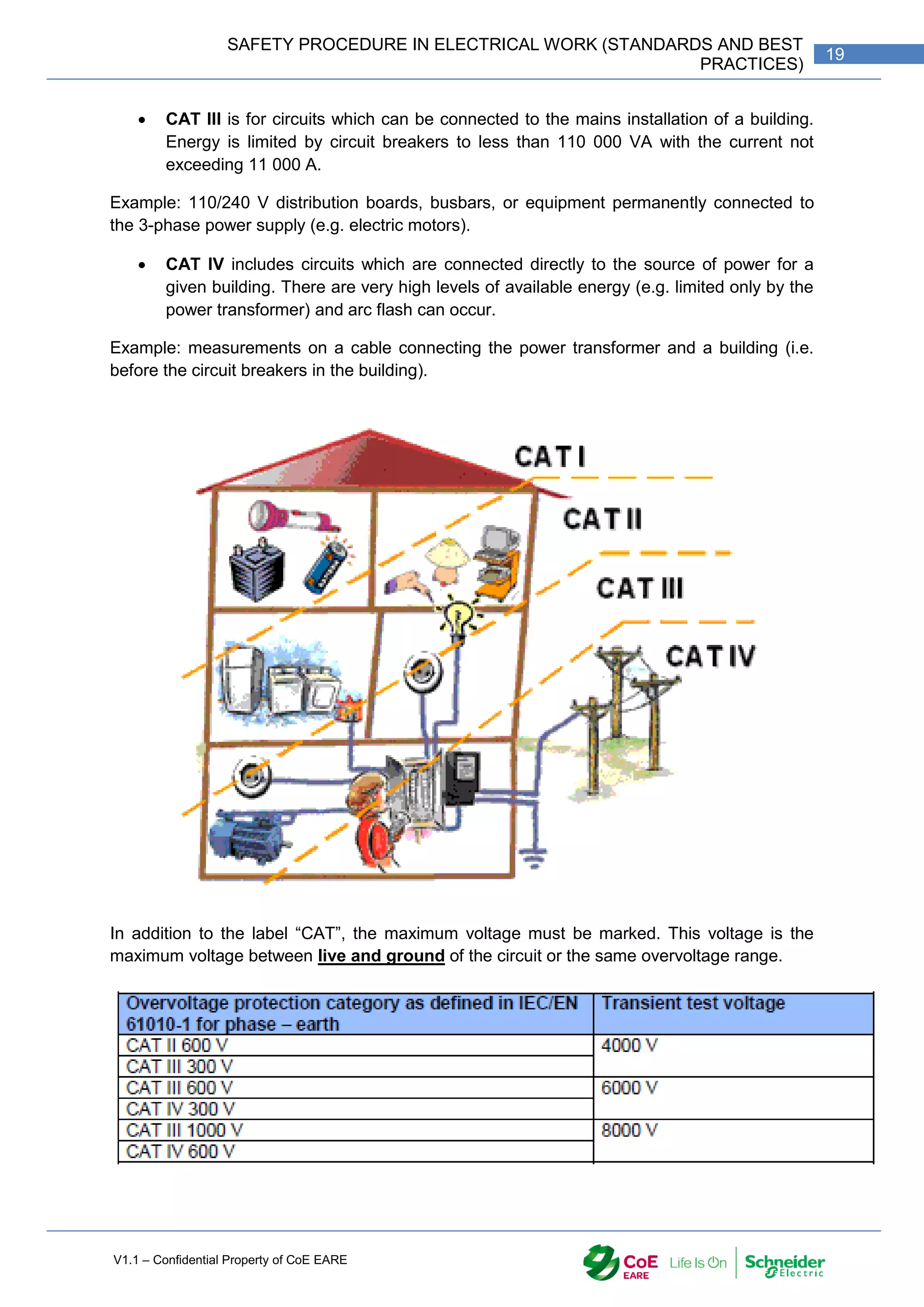
There are four categories designated by a mark such as “CAT III, 150 V" or "CAT IV, 1000
V".
CAT I is applicable to instruments and equipment, which are not intended to be
connected to the mains supply. Because the available energy is very limited, this
category is normally not marked on the equipment.
Examples: low voltage electronic circuits, load circuits of bench power supplies, etc.
CAT II defines circuits which are intended for direct connection into mains sockets or
similar points. The energy in such installations should be limited to below 100 A
continuously (or below 500 A for voltages not exceeding 150 V). The maximum
available continuous power must be limited (for instance by a circuit breaker) to not
more than 22 000 VA.
Example: a device connected to a 240 V mains socket with 13 A fuse (energy limited to 3100
VA)](https://image.slidesharecdn.com/iaindustrialautomation-part1-210930233627/75/Ia-industrial-automation-part-1-20-2048.jpg)
![V1.1 – Confidential Property of CoE EARE
20 [Industrial Automation – Part 1 Installation] [Safety and Security – Basic Industrial wiring]
Rated Voltage IEC 61010-1 2nd Edition
CAT IV CAT III CAT II
150V 4,000V 2,500V 1,500V
300V 6,000V 4,000V 2,500V
600V 8,000V 6,000V 4,000V
1,000V 12,000V 8,000V 6,000V
Resistance 2 ohms 2 ohms 12 ohms
8- SECURITY EQUIPMENT
“It is the duty of all persons who may be concerned with the installation, operation and
maintenance of electric lines and apparatus to make themselves thoroughly conversant with
the regulations and safety rules governing the work they may have to undertake on these
lines and apparatus.” (IS.5216.1.1.1982 § 2.1)
8.1- PERSONAL PROTECTIVE EQUIPMENT (PPE)
Personal protective equipment (PPE) is all equipment needed to
protect an electrician against electric shock to protect himself. Each
worker undertakes the responsibility of its protective equipment and
must check the condition on each equipment before use. Any
damaged equipment should be not used and be replaced.
The PPE are:
safety glasses
face shields
hard insulated hats
safety isolated shoes
insulating (rubber) gloves with leather
protectors
insulating sleeves
flame-resistant (FR) clothing](https://image.slidesharecdn.com/iaindustrialautomation-part1-210930233627/75/Ia-industrial-automation-part-1-22-2048.jpg)

![V1.1 – Confidential Property of CoE EARE
22 [Industrial Automation – Part 1 Installation] [Safety and Security – Basic Industrial wiring]
9- MEASURING DEVICES
Make an electrical measurement is one of the situations where the risk of electric shock is
important. The electrician should be sure that the measuring device is in good condition and
matches some rules.
The measuring device should:
Have an insulating case
Be Class II
Have an IP2X
Have the right measurement category.
All accessories have to match those rules.
10- PERMIT-TO-WORK SYSTEM
All work on major electrical installations shall be carried out under permit-to-work system
which is now well established, unless standing instructions are issued by the competent
authority to follow other procedures except in extenuating circumstances (saving life…) in
this case the action taken shall be reported to the person-in-charge. The permit-to-work
certificate from the person-in-charge of operation to the person-in-charge of the men
selected to carry out any particular work ensures that the portion of the installation where the
work is to be carried out is rendered -dead and safe for working. All work shall be carried out
under the personal supervision of a competent person. If more than one department is
working on the same apparatus, a permit-to- work should be issued to the person-in-charge
of each department.
No work shall be commenced on live mains unless it is specifically intended to be so done by
specially trained staff. In such cases all possible precautions shall be taken to ensure the
safety of the staff engaged for such work, and also of others who may be directly or indirectly
connected with the work. Such work shall only be carried out with proper equipment provided
for the purpose and, after taking necessary precautions, by specially trained and experienced
persons who are aware of the danger that exists when working on or near live mains or
apparatus.
The permit is to be prepared in duplicate by the person-in-charge of operation on the
basis of message, duly logged, from the person-m-charge of the work.
The original permit will be issued to the person-in-charge of work and the duplicate
will be retained in the permit book. For further allocation of work by the permit
receiving officer, tokens may be issued to the workers authorizing them individually to
carry out the prescribed work.
On completion of the work, the original shall be returned to the issuing officer duly
discharged for cancellation.
11- EXAMPLE OF PERMIT-TO-WORK IN APPENDIX
Appendix 1](https://image.slidesharecdn.com/iaindustrialautomation-part1-210930233627/75/Ia-industrial-automation-part-1-24-2048.jpg)
![V1.1 – Confidential Property of CoE EARE
24 [Industrial Automation – Part 1 Installation] [Safety and Security – Basic Industrial wiring]
13- ELECTRICAL AUTHORIZATION
13.1- PREAMBLE:
The IEC 61010 defines the roles and duties to everyone involved in the electrical work. This
standard has been made to protect worker against electrical hazards.
13.2- PRINCIPLE:
People (electrician or not) give an authorization to do work related to electricity. This
authorization is given for particular task and certifies that the owner of the authorization
knows about risks and danger of electricity.
This authorization is required for:
Enter in electrical room.
Do electrical work. (Measurement, maintenance …)
Manage electrical work
Shut down power and lock switch-disconnector.
Do electrical test
Be a safety watcher
The employer is responsible to give the “Electrical Authorization”. He has to check that the
employee has the required knowledge on:
Present electric hazards;
Taking care of its own security and the security to people under its supervision;
The action to do in case of accident
The ability of the employee to do the work and tasks.
13.3- THE ELECTRICAL AUTHORIZATION
The Electrical Authorization is delivered by the employer to its selected employees under
its responsibility and it is only valid for the time of working to the company.
The Electrical Authorization is a document filed in by the employer and signed by the
employer and the employee.
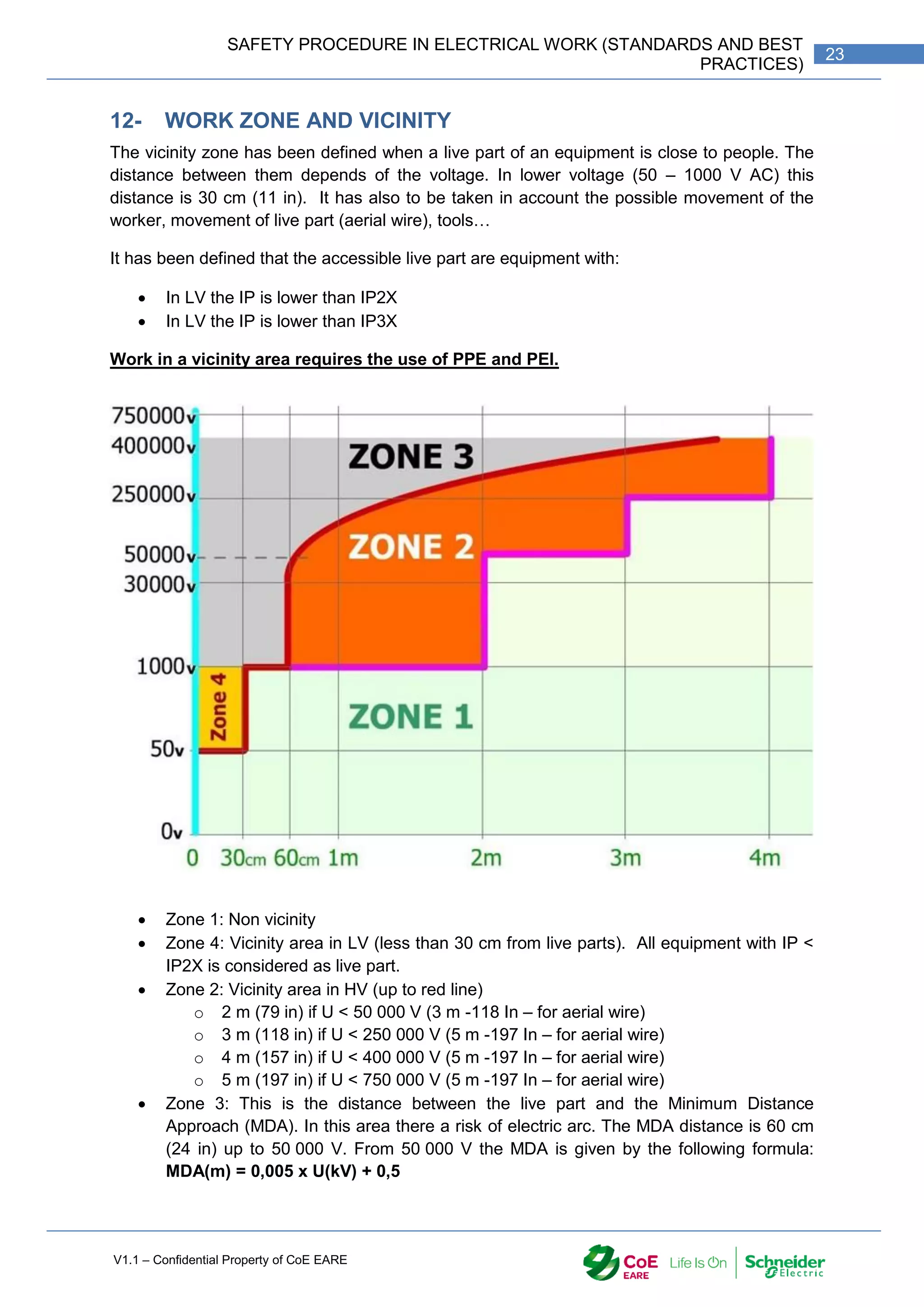
13.4- WORK ZONE AND VICINITY
(As defined in the section 13.4-)
13.5- SYMBOLS AND CLASSIFICATION
The Electrical Authorization is defined by a letter, a number and a letter.
B x V
Who? What?
Where?
Second letter:
Type of work.
Number:
Function.
First letter:
Voltage level](https://image.slidesharecdn.com/iaindustrialautomation-part1-210930233627/75/Ia-industrial-automation-part-1-26-2048.jpg)
![V1.1 – Confidential Property of CoE EARE
26 [Industrial Automation – Part 1 Installation] [Safety and Security – Basic Industrial wiring]
13.6- WORK DEFINITION
13.6.1- NON ELECTRICIAN B0 / H0 OR H0V
The holder can access to the electrical room without supervision and execute or manage no
electrical tasks such as painting, cleaning…
13.6.2- EMPLOYEE IN CHARGE OF THE CLEANING UNDER VOLTAGE (N)
Employee managing or doing cleaning work under voltage.
13.6.3- ELECTRICIAN EXECUTANT B1 / H1 OR B1V / H1V
Employee that works as electrician and who is following instruction. He is aware of its
security.
He can access to the electric room without authorization.
He can perform work and Operation near live parts.
He can perform measurement with clampmeter
He is working in team under the supervision of the Responsible for electrical work
(B or H2) or Responsible of Intervention (BR)
The holder of B1V or H1V can work in vicinity.
13.6.4- RESPONSIBLE IN CHARGE OF THE ELECTRIC WORK (B2 / H2 –
B2V / H2V)
The holder of the B2 or H2 manages the work and the tasks and takes all actions to ensure
its security and the security of people under its supervision.
He is responsible of the execution of its security order.
It can receive an acknowledgment of lockout and sign it
The older is also 0 and 1
The holder of B2V or H2V can work in vicinity.
13.6.5- RESPONSIBLE IN CHARGE OF THE LOCKOUT (BC / HC)
The holder of a BC is performing the Power disconnection of equipment by opening a switch
disconnector and locks it with proper lock. He takes all action to guaranty the safety and
security.
He has to have the agreement from the Responsible of site
He executes the four steps of the lockout or only the two first. In this case, the last
two steps are done by the Responsible in charge of the electric work.
The BC or HC Electrical Authorisation doesn’t allow the holder to supervise the
security.
13.7- INTERVENTIONS
13.7.1- RESPONSIBLE IN CHARGE OF INTERVENTION (BR)
The holder can be assisted by an Electrician executant on equipment which has previously
been lockout.
The Responsible in charge of Intervention (BR) is designated.](https://image.slidesharecdn.com/iaindustrialautomation-part1-210930233627/75/Ia-industrial-automation-part-1-28-2048.jpg)
![V1.1 – Confidential Property of CoE EARE
28 [Industrial Automation – Part 1 Installation] [Safety and Security – Basic Industrial wiring]
It should mention:
Name, surname of the employee
Function of the employee
Employer
Level (s) of Electrical Authorization
date
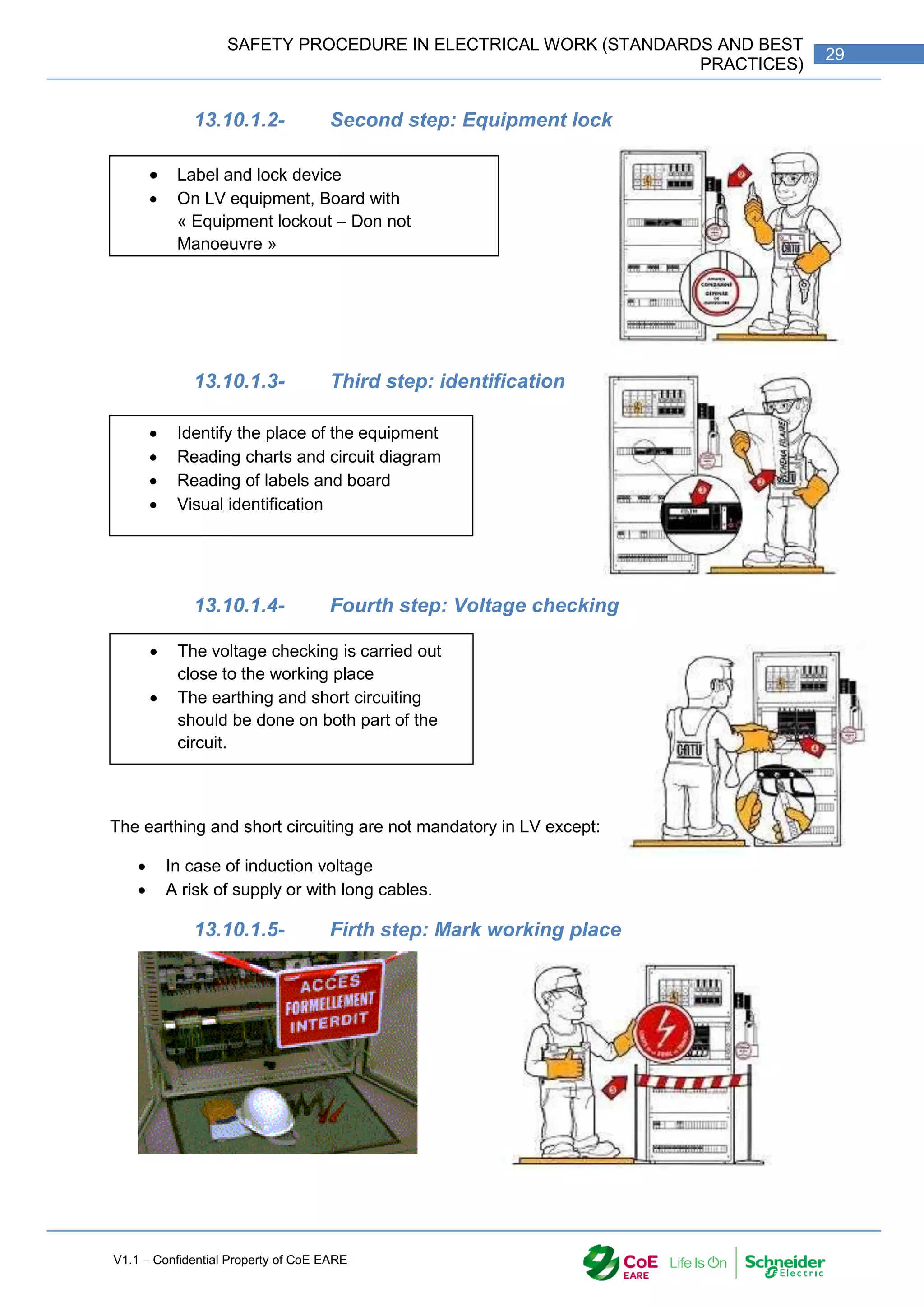
13.10- THE PADLOCKING
This the duty of the holder of BC / HC Electrical Authorization
He does or supervises the lockout
He is responsible of the disconnection of the equipment from the power supply and
the lock of the switch disconnector.
He his establishing the acknowledgment of lockout.
13.10.1- THE FIVE STEPS OF PADLOCKING
13.10.1.1- First step: Disconnection
Acknowledgment
should be signed
2- Lock
1-
Disconnect
3- Identify the
equipment 4- Doing the
Voltage checking
and the earthing
Switch disconnector
Sockets
Withdraw fuse
Plug devices
Control, protesting devices](https://image.slidesharecdn.com/iaindustrialautomation-part1-210930233627/75/Ia-industrial-automation-part-1-30-2048.jpg)
![V1.1 – Confidential Property of CoE EARE
30 [Industrial Automation – Part 1 Installation] [Safety and Security – Basic Industrial wiring]
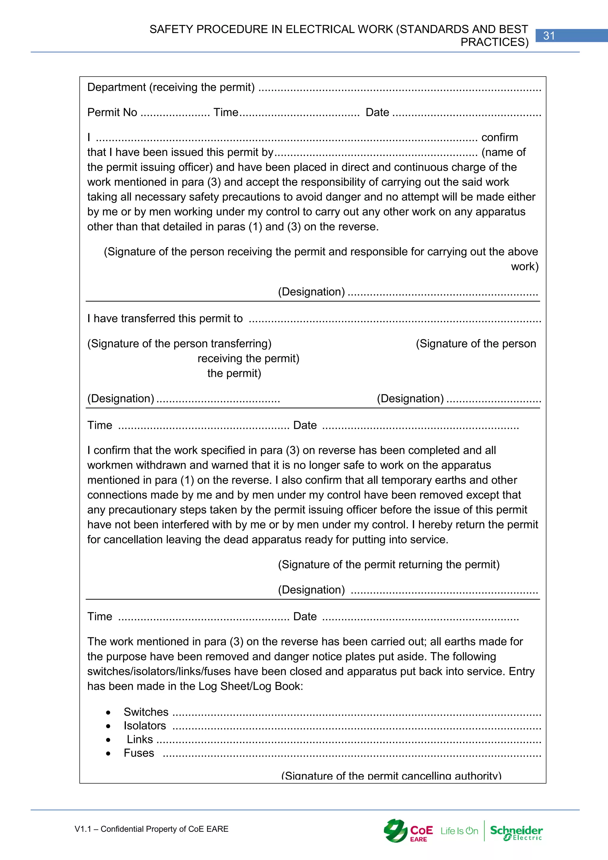
14- APPENDIX
Appendix 1 : Permit-to-work
MODEL FORM OF PERMIT-TO-WORK
Name of the Organization ...................................................................................................
Department (issuing the permit) ............................................................................................
Permit No. .................... Time .....................................Date.................................................
1. I ....................................................................................... certify that the following
apparatus has been made dead, is isolated from all live conductors and has been
connected to earth and the work mentioned in para (3) can now be carried out in
accordance with the safety rules and regulations :
2. For the purpose of making the above apparatus dead, the following
switches/isolators/links/fuses have been opened and the section so isolated has been
earthed at each isolation point and danger notice plates tied thereon:
Switches ....................................................................................................................
Isolators .....................................................................................................................
Links .........................................................................................................................
Fuses .......................................................................................................................
3. Work to be carried out (testing work, if any, to be specifically mentioned):
..............................................................................................................................................
..............................................................................................................................................
..............................................................................................................................................
4. I have also recorded the above operations in the Log Sheet/Log Book including the
instructions for the person who may relieve me.
This permit is now being issued to ................................................................(name of the
person to whom the permit is being issued) for carrying out the work mentioned in para (3).
(Signature of the permit issuing authority)
(Designation) .........................................................](https://image.slidesharecdn.com/iaindustrialautomation-part1-210930233627/75/Ia-industrial-automation-part-1-32-2048.jpg)

![V1.1 – Confidential Property of CoE EARE
34 [Industrial Automation – Part 1 Installation] [Safety and Security – Basic Industrial wiring]
DEVICES IN INDUSTRIAL WIRING](https://image.slidesharecdn.com/iaindustrialautomation-part1-210930233627/75/Ia-industrial-automation-part-1-36-2048.jpg)
![V1.1 – Confidential Property of CoE EARE
36 [Industrial Automation – Part 1 Installation] [Safety and Security – Basic Industrial wiring]
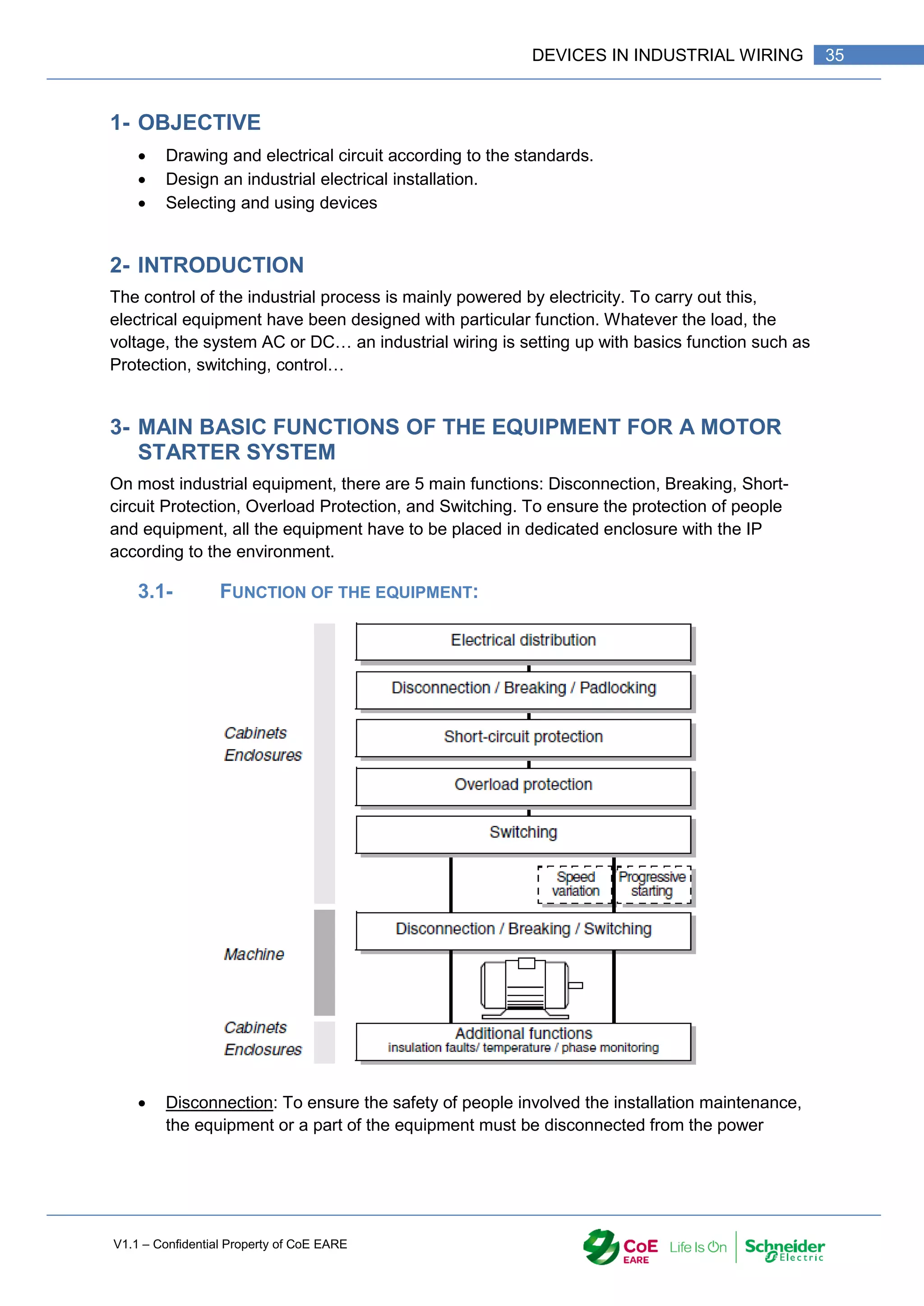
supply. A padlocking mechanism may be added to the disconnection device to
procure more protection.
Breaking: The breaking function is mandatory to be able to break the power supply
(on full load) in case of emergency.
Short-circuit Protection: To avoid accidental damages on the equipment, disturbance
on the network (Unbalance), risk for the people security, the short circuit must be
detected and the faulty circuit have to be quickly opened.
Overload Protection: Mechanical overloads and supply network faults are the most
common causes of the overload withstood by motors. This results in a considerable
increase in current drawn up by the motor, resulting in excessive temperature rise
and greatly reducing motor lifetime. It could even lead to destruction of the motor.
Motor overload must therefore be detected.
Switching: Its function is to make and break the motor supply circuit.
4- DEVICES OR EQUIPMENT USED FOR THESE FUNCTIONS
Sizing and implementation of this equipment must comply with standards rules. A particular
attention is done on the discrimination and cascading of the protection and breaking.
5- DISCONNECTOR / SWITCH DISCONNECTOR / SWITCH FUSE
DISCONNECTOR
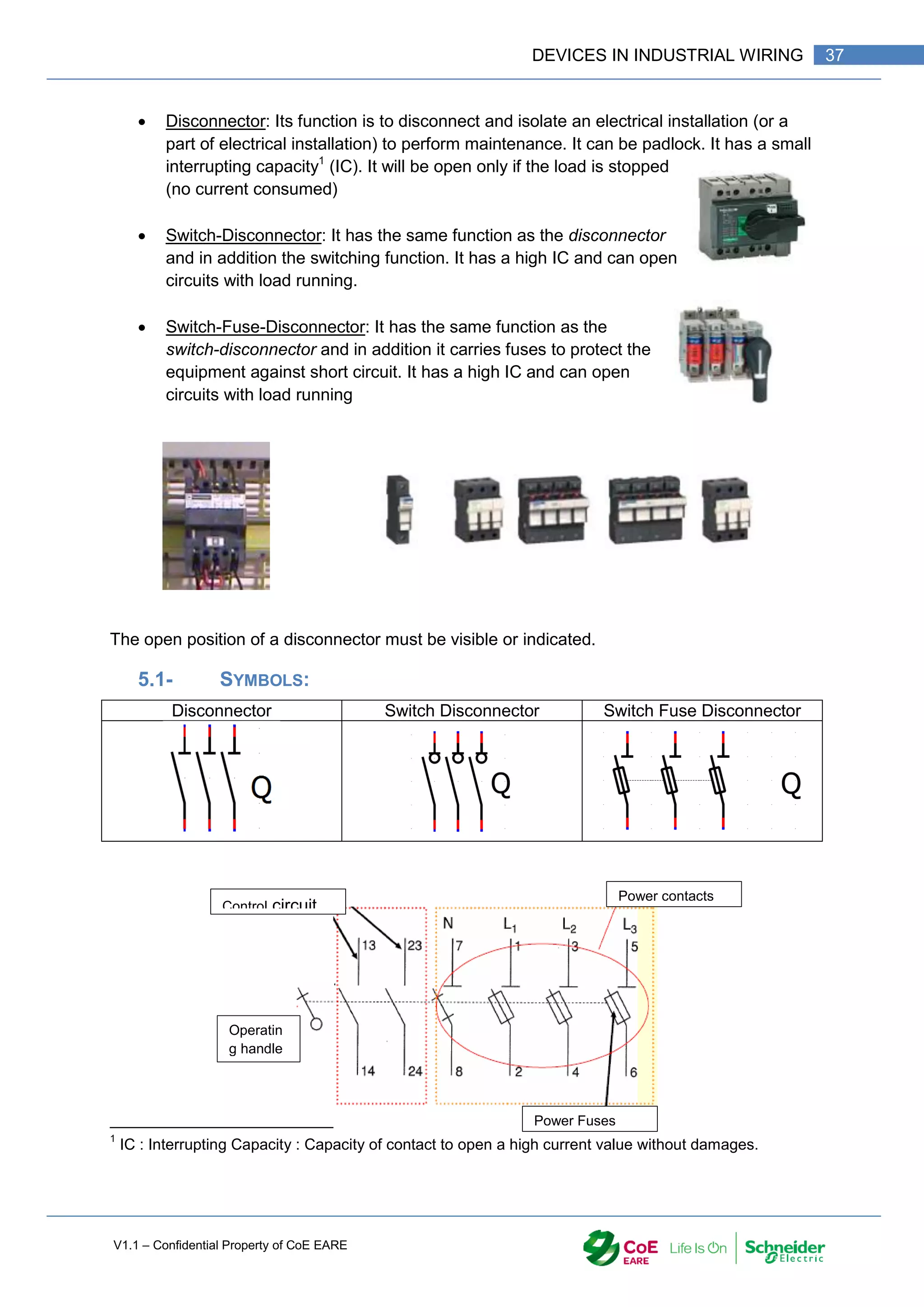
The use of disconnector is mandatory in industrial wiring. It is used
to isolate the electrical panel from the power supply.](https://image.slidesharecdn.com/iaindustrialautomation-part1-210930233627/75/Ia-industrial-automation-part-1-38-2048.jpg)
![V1.1 – Confidential Property of CoE EARE
38 [Industrial Automation – Part 1 Installation] [Safety and Security – Basic Industrial wiring]
5.2- AM OR GG FUSES:
gG Fuses protect against short circuit in an electrical installation, mainly for resistive
load.
aM Fuses protect against short circuit in electrical installation with Inductive load such
as Induction engine or transformer.
5.3- TYPE OF FUSE:
Depending on the local standards, fuses can have different design.
NFC/Din Fuses type BS Fuses CC Fuses type J Fuse type
5.4- SELECTION CRITERIA
5.5- EXAMPLE
Find the reference of Switch Fuse Disconnector and the fuses to supply a Pa=10 kW
induction motor (cos 𝜌 = 0.851,) with a 3* 400V network and
𝑃𝑎 = √3 ∗ 𝑈 ∗ 𝐼 ∗ cos 𝜌
𝐼 =
𝑃𝑎
√3 ∗ 𝑈 ∗ cos𝜌
=
10 000
√3 ∗ 400 ∗ 0.851
= 16.98𝐴
• 1P + N: Phase + Neutral
• 2P: Two Phases
• 3P: Triphase
• 3P+N: Triphase + Neutral
No of
Poles
• Rated Voltage Ue; Maximum voltage between 2 poles.
Rated
Voltage
• Maximun curent that the device can support without any damages
Rating
• gG or aM depending of the load
Fuses Type
• 1 or 2 control contact
No of control
contact
• Type of Operatin Handle
• Clamping system
• Padlocking system
Accesories
Switch Fuse Disconnector
reference](https://image.slidesharecdn.com/iaindustrialautomation-part1-210930233627/75/Ia-industrial-automation-part-1-40-2048.jpg)
![V1.1 – Confidential Property of CoE EARE
40 [Industrial Automation – Part 1 Installation] [Safety and Security – Basic Industrial wiring]
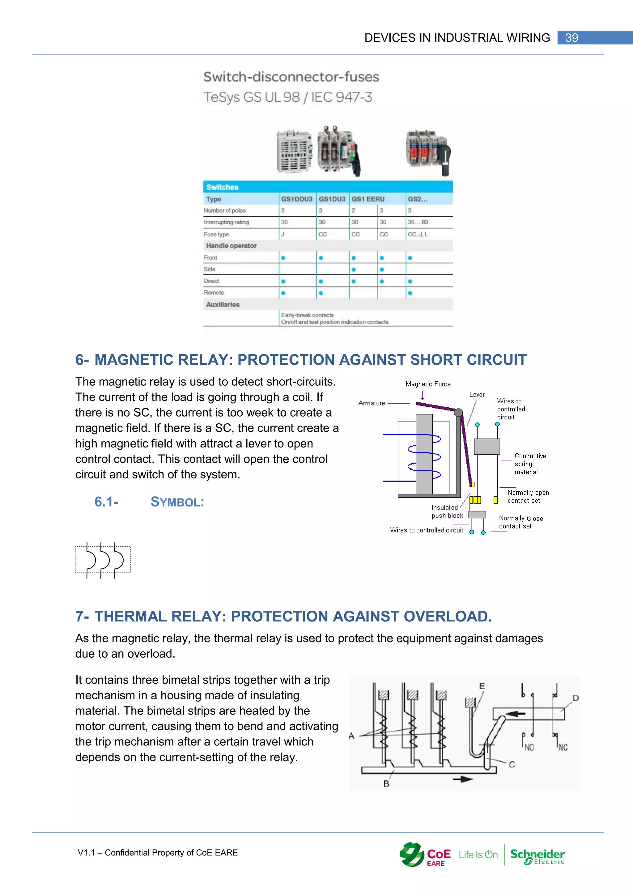
The release mechanism actuates an auxiliary switch that breaks the coil circuit of the motor
contactor (Figure 1). A switching position indicator signals the condition “tripped”.
A = Indirectly heated bimetal strips
B = Trip slide
C = Trip lever
D = Contact lever
E = Compensation bimetal strip
7.1- SYMBOL:
Power circuit: Control circuit or
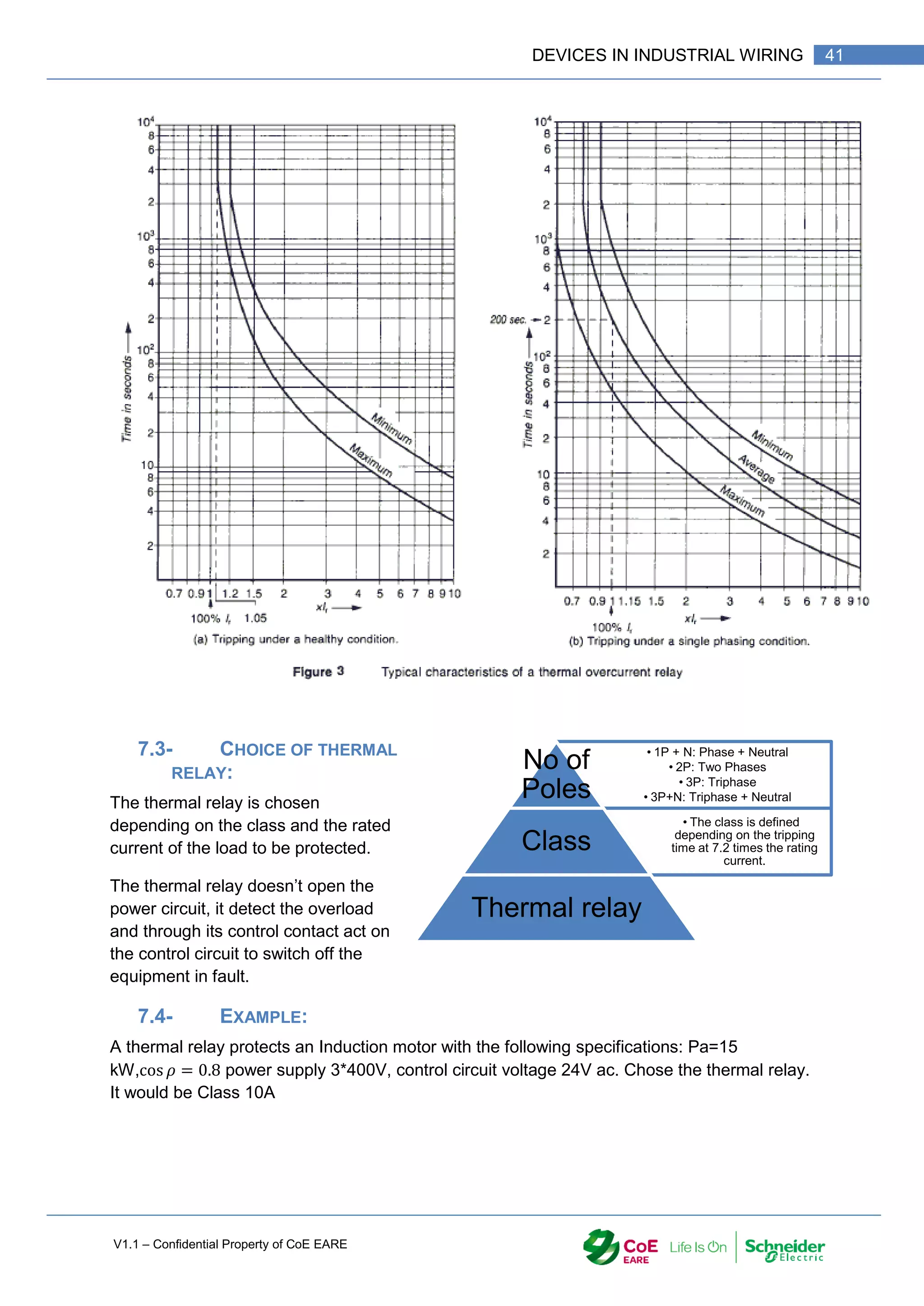
7.2- CLASS OF THE THERMAL RELAY:
The class of thermal relay define its behaviour in case of overload and the tripping time.](https://image.slidesharecdn.com/iaindustrialautomation-part1-210930233627/75/Ia-industrial-automation-part-1-42-2048.jpg)
![V1.1 – Confidential Property of CoE EARE
42 [Industrial Automation – Part 1 Installation] [Safety and Security – Basic Industrial wiring]
𝐼 =
𝑃𝑎
√3 ∗ 𝑈 ∗ cos 𝜌
=
15 000
√3 ∗ 400 ∗ 0.8
= 27𝐴
Thermal relay: LRD 32, setting at 27 A
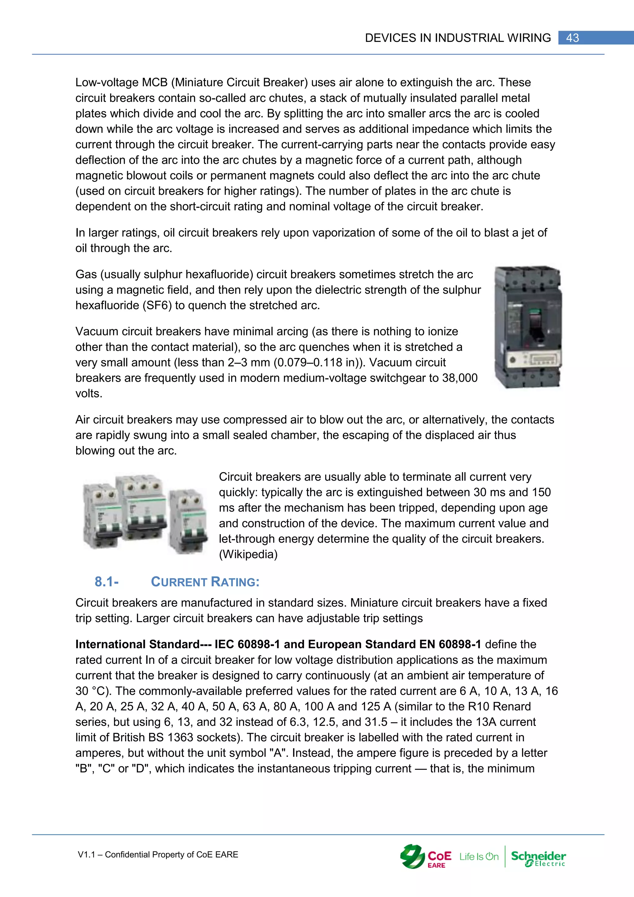
8- CIRCUIT BREAKER
A circuit breaker is an automatically operated electrical switch designed to protect an
electrical circuit from damage caused by Overcurrent/overload or short circuit. Its basic
function is to interrupt current flow after Protective relays detect faults condition. Unlike a
fuse, which operates once and then must be replaced, a circuit breaker can be reset (either
manually or automatically) to resume normal operation. Circuit breakers are made in varying
sizes, from small devices that protect an individual household appliance up to large
switchgear designed to protect high voltage circuits feeding an entire city. (Wikipedia)
As per the nature of the current, especially in case of short circuit, the circuit breaker has the
ability to cut electric arc. For this, different methods are used:](https://image.slidesharecdn.com/iaindustrialautomation-part1-210930233627/75/Ia-industrial-automation-part-1-44-2048.jpg)
![V1.1 – Confidential Property of CoE EARE
44 [Industrial Automation – Part 1 Installation] [Safety and Security – Basic Industrial wiring]
value of current that causes the circuit breaker to trip without intentional time delay (i.e., in
less than 100 ms), expressed in terms of In:
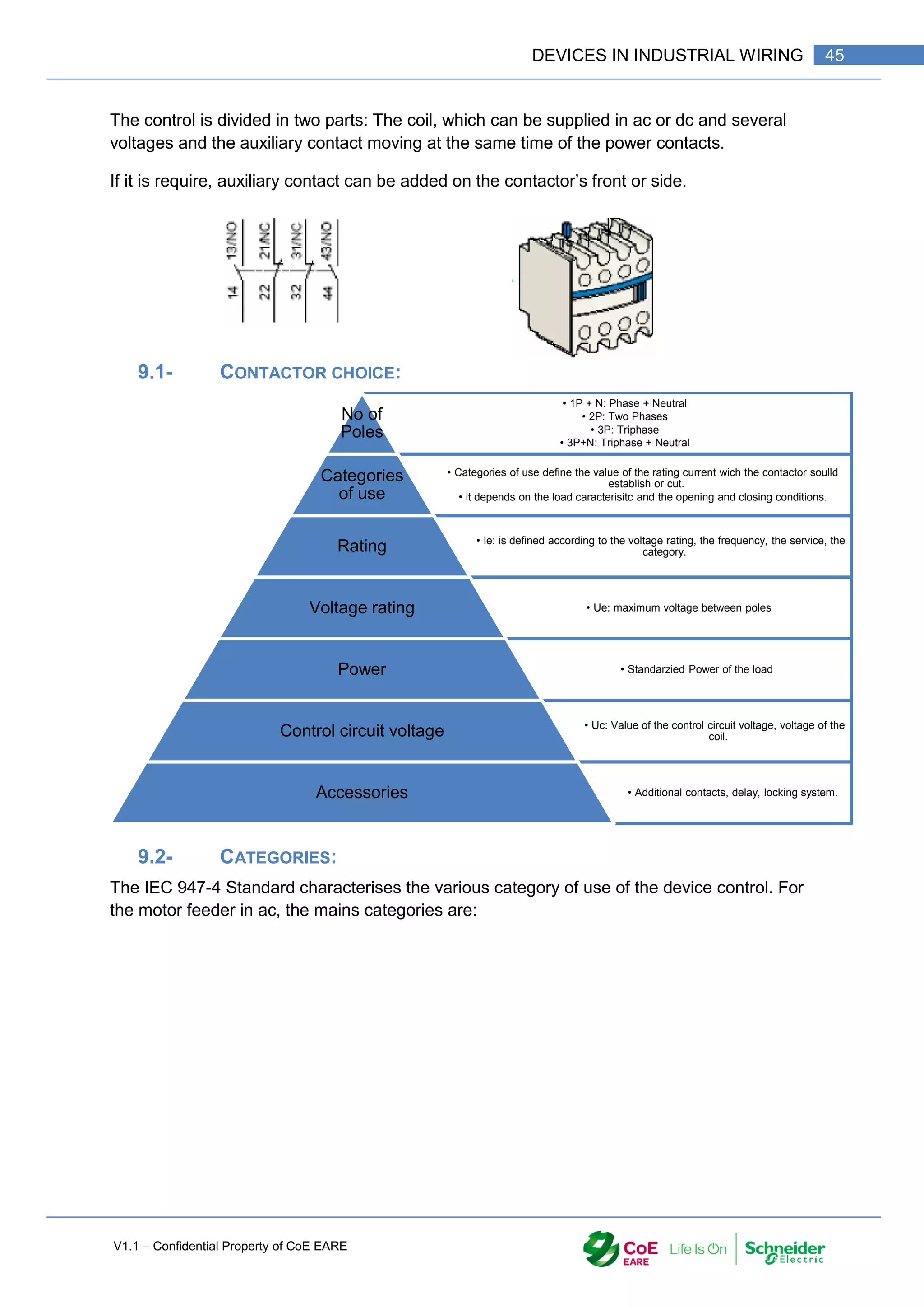
9- THE CONTACTOR
A contactor is an electrically controlled switch used for switching an electrical power circuit,
similar to a relay except with higher current ratings. A contactor is controlled by a circuit
which has a much lower power level than the switched circuit.
A contactor is composed on two parts: Power and control part.
The power part is composed of contacts (3 / 4) with high Interruption capacity. All contact are
closing or Opening at the same time. They are moved by the coil of the control circuit. When
this one is supplied, it attracts the moving part and the power contacts are closing. In
contrary, when the coil is not powered, a spring move back the moving part and the power
contacts are opening. A contactor is a switch controlled by a coil.
The power part can have 1, 2, 3 or 4 contacts. They can be Normally Open or Normally
Closed. The rating depends on the load current.
Power part
Control part Auxiliary contacts](https://image.slidesharecdn.com/iaindustrialautomation-part1-210930233627/75/Ia-industrial-automation-part-1-46-2048.jpg)
![V1.1 – Confidential Property of CoE EARE
46 [Industrial Automation – Part 1 Installation] [Safety and Security – Basic Industrial wiring]
9.3- SYMBOLS:](https://image.slidesharecdn.com/iaindustrialautomation-part1-210930233627/75/Ia-industrial-automation-part-1-48-2048.jpg)
![V1.1 – Confidential Property of CoE EARE
48 [Industrial Automation – Part 1 Installation] [Safety and Security – Basic Industrial wiring]
1- INTRODUCTION
Electrical diagram is the part of the industrial system. It is one of the first steps in the design
process of an industrial system or machine. It is not an architectural representation (in
industrial), it shows the devices used in the system and the connections between them.
Symbols used have been designed and standardized to be readable by
every technician.
2- SYMBOLS USED
There are plenty of symbols representing an electrical device. To be able
to be read by every technician, symbols were standardized and an
international standard created: The IEC IEC60617 – part 7. Local
standards have been designed by following the IEC one.
The IEC 60617 is available on annexe files. (IEC60617 Symbols.pdf)
The target of the electrical diagram is the readability of the operation of
the different circuits (Control, Power … circuits)
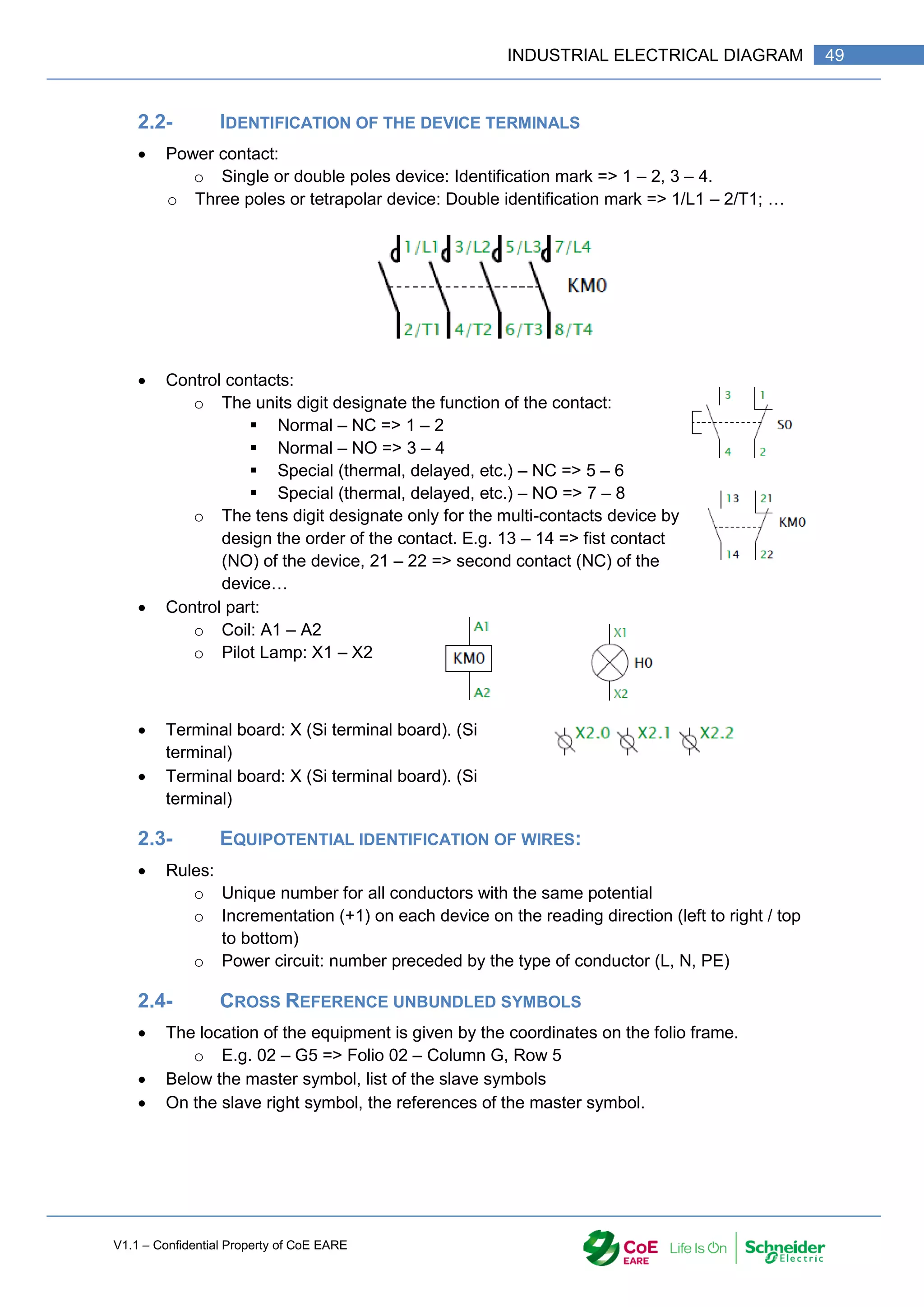
2.1- SYMBOLIZATION OF DEVICES
Main contacts: Power circuit
o From 0 (control device) to 4 power contacts.
o Always represented together, they are drawn in solid line
Auxiliary contacts: Control circuit
o From 0 to 5 contacts, more with the use of add
o Ungrouped, drawn in fine line
o 2 types: Normally Open (NO), Normally Closed (NC)
o Mechanically linked to the control part they indicate the state of the device. By
this, the state of a device can be used in a control circuit.
Control part (control of the contacts) Operated by Pushing
o Manual: drawn on the contact’s left side.
o Electric (coil) load of the control circuit
Mechanical link:
o Partially drawn if it disturbs the reading of the electrical diagram.
Power part
Control part
Mechanical link
Auxiliary contacts](https://image.slidesharecdn.com/iaindustrialautomation-part1-210930233627/75/Ia-industrial-automation-part-1-50-2048.jpg)
![V1.1 – Confidential Property of CoE EARE
50 [Industrial Automation – Part 1 Installation] [Safety and Security – Basic Industrial wiring]](https://image.slidesharecdn.com/iaindustrialautomation-part1-210930233627/75/Ia-industrial-automation-part-1-52-2048.jpg)
![V1.1 – Confidential Property of CoE EARE
52 [Industrial Automation – Part 1 Installation] [Safety and Security – Basic Industrial wiring]
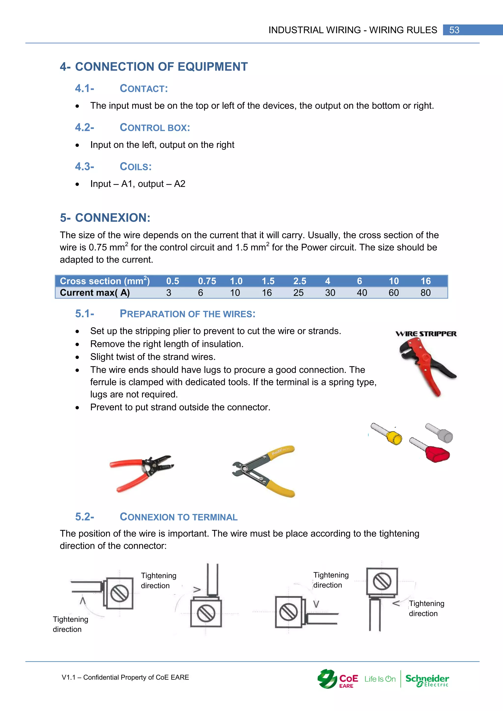
1- OBJECTIVE
Drawing and electrical circuit according to the standards.
Design an industrial electrical installation.
Understanding wiring procedure
2- HARDWARE LOCATION:
To implement the devices on a mesh in cabinet, it is recommended following the rules
hereafter:
2.1- SPACE BETWEEN
DEVICES:
Wiring by using raceway: leave
4 to 6 cm between the devices
and the raceway.
Wiring in strand: Leave 4 to 6
cm between devices
2.2- COMMON
FUNCTIONS:
it is recommended to place
side to side the equipment with
common function e.g.
contactor forward / reverse,
contactor going up / down…
The rating plate of the contactor coil should be accessible for reading.
3- WIRE COLOUR:
For the power circuit the following colour should be used:
Phase 1: Brawn (red)
Phase 2: Black (Yellow)
Phase3: Grey (Black)
Neutral: Blue
Earthing: Yellow /green
Note that the phases can be wired with one colour; in this case, the marking is mandatory.
The control circuit will be wired in grey. Other colour can be used but the marking is
mandatory.](https://image.slidesharecdn.com/iaindustrialautomation-part1-210930233627/75/Ia-industrial-automation-part-1-54-2048.jpg)
![V1.1 – Confidential Property of CoE EARE
54 [Industrial Automation – Part 1 Installation] [Safety and Security – Basic Industrial wiring]
If there is two wire, place them on both sides of the terminal
Note that two wire maximum must be connected to one terminal.
5.3- WIRING RULES:
Regarding the wiring in raceway, the following rules must be followed:
Wire the power circuit before the control circuit.
For the control circuit: wire first the coil return (A2 terminals) then the button box, then
the cabinet door and finally the mesh.
The bridge between two terminals should be run
through the raceway.
The length of the wire should be enough to
shape it.
Wire must come perpendicularly to the device or
terminal
Wire terminal block from left to right and from
top to bottom.
For a comb wiring, wire must be parallel
The link to the loads, sensors should be made by cables.
The identification of the wire is given by the equipotential number on the diagram.
This identification can be letters, numbers or both. The identification is made with
ring, clips or direct printing.
All devices should be marked with specific tag.
Check the tightening.
5.4- WIRING PROCEDURE
Check with Multimeter the state of the contact](https://image.slidesharecdn.com/iaindustrialautomation-part1-210930233627/75/Ia-industrial-automation-part-1-56-2048.jpg)
![V1.1 – Confidential Property of CoE EARE
56 [Industrial Automation – Part 1 Installation] [Safety and Security – Basic Industrial wiring]
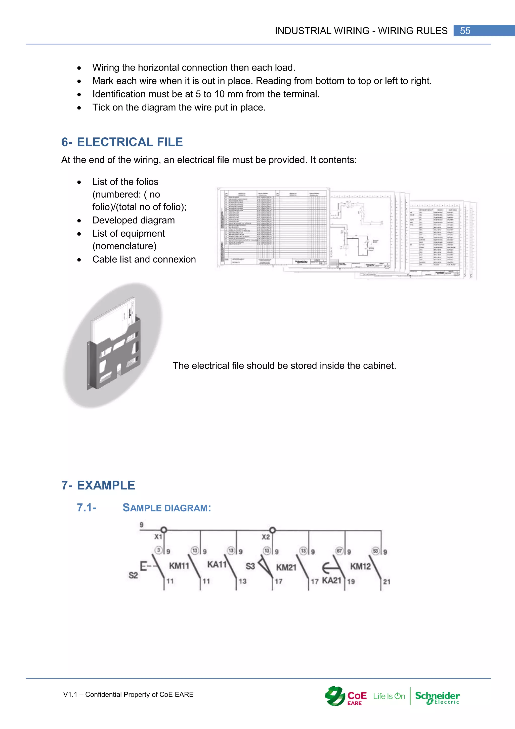
7.2- REAL WIRING DIAGRAM](https://image.slidesharecdn.com/iaindustrialautomation-part1-210930233627/75/Ia-industrial-automation-part-1-58-2048.jpg)
![V1.1 – Confidential Property of CoE EARE
58 [Industrial Automation – Part 1 Installation] [Safety and Security – Basic Industrial wiring]
1- OBJECTIVE
Select the equipment in order to design an electrical circuit
Design an industrial electrical installation.
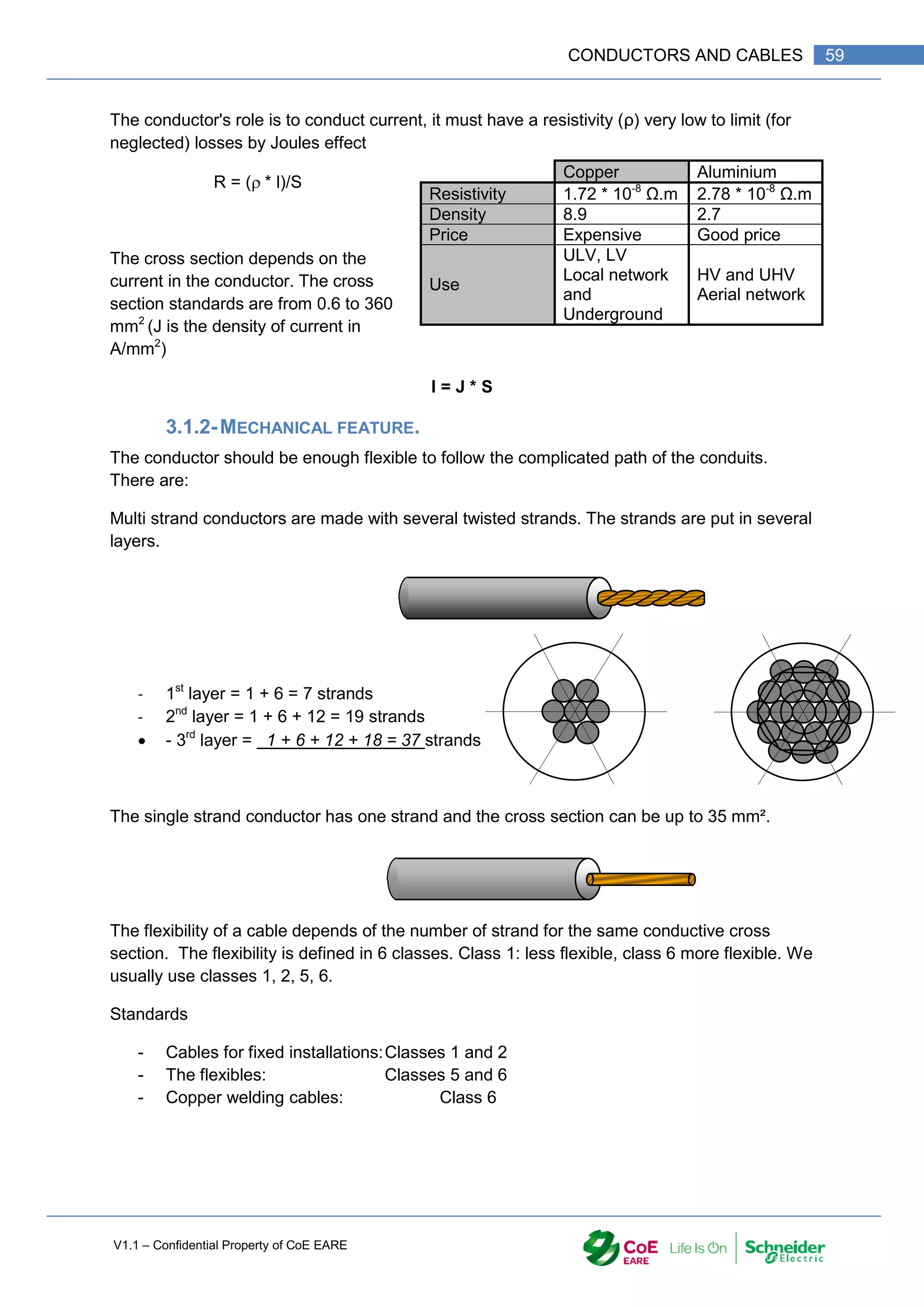
2- CONDUCTORS AND CABLES:
They are the active part of the electrical links. Their duty is to carry the electrical
current. There is a large range of conductor and cable.
- An insulated conductor is an association between a conductor and insulation
- A single core cable is an Insulated conductor with one or more protective sheath.
- A cable is a bundle of conductors electrically insulated sharing the protective sheath.
3- GENERAL STRUCTURE.
A conductor or Cable is made with two essentials parts; each has its own function
(conductive or insulating)
3.1- CONDUCTIVE PART.
3.1.1-ELECTRICAL FEATURES.
Conductor
Insulation
Protective sheath
Insulation
Conductor
Protective sheath
Conductor
Insulation](https://image.slidesharecdn.com/iaindustrialautomation-part1-210930233627/75/Ia-industrial-automation-part-1-60-2048.jpg)
![V1.1 – Confidential Property of CoE EARE
60 [Industrial Automation – Part 1 Installation] [Safety and Security – Basic Industrial wiring]
Class 1 Class 2 Class 3 Class 4 Class 5 Class 6
médiocre
Poor
Solid
Conductor
Passable
Passable
Bon
good
Tres bon
Very good
Excellent
Excellent
Exceptionnel
Exceptional
Extra-flexible
3.2- INSULATION PART: (DIELECTRIC)
Insulation performs the insulation between conductors with different voltages and the ground
or the earth. The insulation should have a very high resistivity.
Currently, synthetic plastics have replaced insulator like paper, natural rubber. The main
insulation is made with:
- Polyvinyl chloride (PVC) or polyethylene (PE)
- Chemically cross-linked polyethylene (PRC)
Insulations used are characterized for their rated voltage isolation. The nominal voltage of
the cable must be at least equal to the nominal voltage of the installation (different voltages
250V, 300V, 500V, 750V, 1000V).
Cross
section
Conductors Cross
section
Conductors
mm² Class 1 Class 2 Class 3 mm² Class 4 Class 5 Class 6
1.5
2.5
4
6
10
16
25
35
50
70
95
120
150
185
240
300
400
500
630
800
1 000
1 x 1.38
1 x 1.78
1 x 2.25
1 x 2.76
1 x 3.57
1 x 4.50
1 x 5.65
1 x 6.60
7 x 2.93
19 x 2.85
19 x 3.20
37 x 2.85
37 x 3.20
7 x 0.50
7 x 0.67
7 x 0.85
7 x 1.04
7 x 1.35
7 x 1.70
7 x 2.14
7 x 2.52
19 x 1.78
19 x 2.14
19 x 2.52
37 x 2.03
37 x 2.25
37 x 2.52
61 x 2.25
61 x 2.52
61 x 2.85
61 x 3.20
127 x 2.52
127 x 2.85
127 x 3.20
12 x 1.04
19 x 1.04
19 x 1.35
16 x 1.53
27 x 1.53
37 x 1.57
37 x 1.78
61 x 1.60
61 x 1.78
91 x 1.60
0.5
0.75
1
1.5
2.5
4
6
10
16
25
35
50
70
95
120
150
185
240
300
400
500
7 x 0.30
11 x 0.30
14 x 0.30
12 x 0.40
20 x 0.40
20 x 0.50
30 x 0.50
49 x 0.50
56 x 0.60
84 x 0.60
98 x 0.67
144 x 0.67
192 x 0.67
266 x 0.67
342 x 0.67
266 x 0.85
330 x 0.85
420 x 0.85
518 x 0.85
672 x 0.85
854 x 0.85
16 x 0.20
24 x 0.20
32 x 0.20
30 x 0.25
50 x 0.25
56 x 0.30
84 x 0.30
80 x 0.40
126 x 0.40
196 x 0.40
276 x 0.40
396 x 0.40
360 x 0.50
475 x 0.50
608 x 0.50
756 x 0.50
925 x 0.50
1221 x 0.50
1525 x 0.50
2013 x 0.50
1769 x 0.60
28 x 0.15
42 x 0.15
56 x 0.15
85 x 0.15
140 x 0.15
228 x 0.15
189 x 0.20
324 x 0.20
513 x 0.20
783 x 0.20
1107 x 0.20
702 x 0.30
909 x 0.30
1332 x 0.30
1702 x 0.30
2109 x 0.30
2590 x 0.30
3360 x 0.30
4270 x 0.30](https://image.slidesharecdn.com/iaindustrialautomation-part1-210930233627/75/Ia-industrial-automation-part-1-62-2048.jpg)
![V1.1 – Confidential Property of CoE EARE
62 [Industrial Automation – Part 1 Installation] [Safety and Security – Basic Industrial wiring]
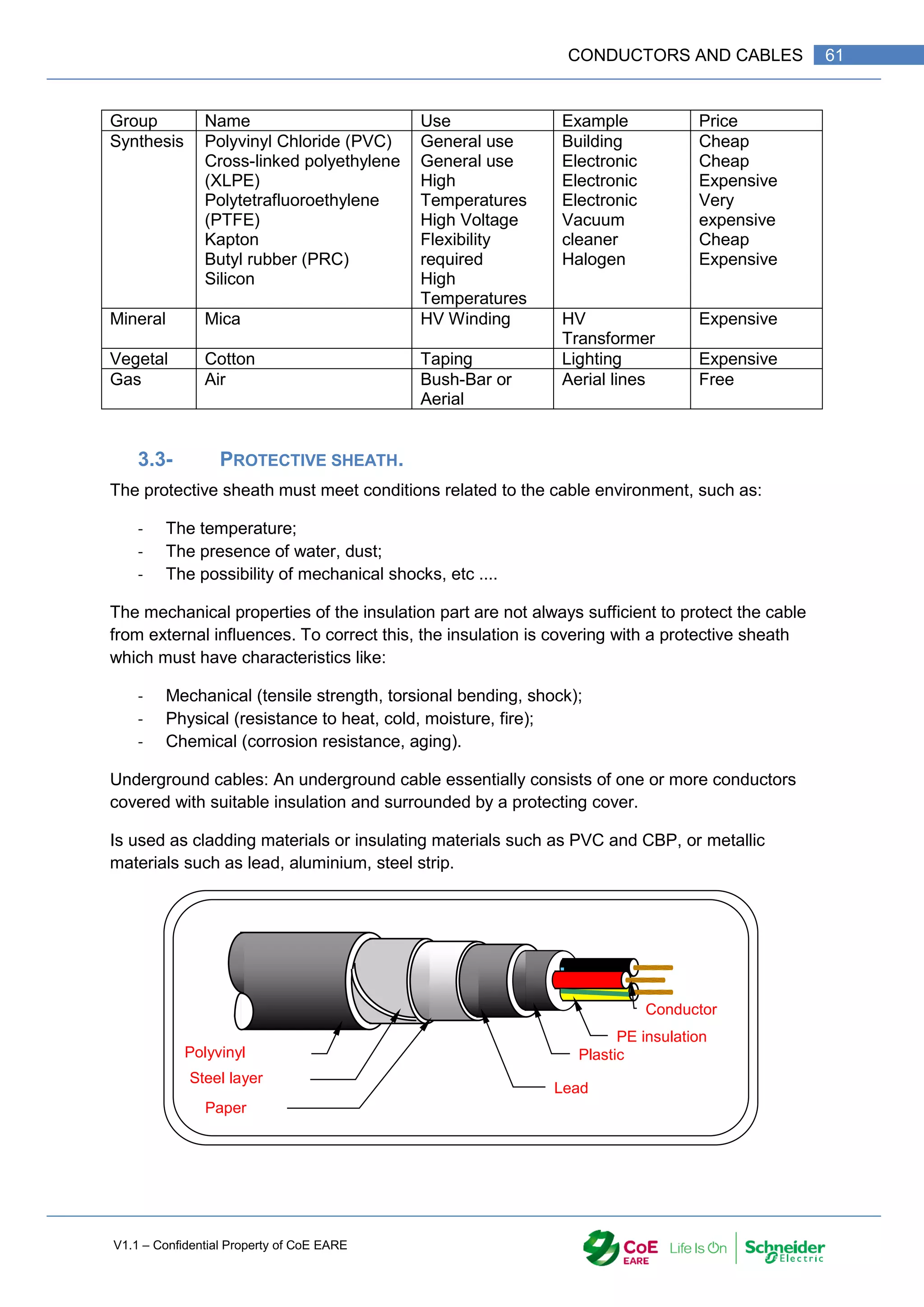
4- CONSTRUCTION OF CABLES:
The various parts of underground cables are as under as shown in the picture.
4.1- LV CABLE
4.2- HV CABLE
5- NUMBER OF WIRE IN A PIPE:
Whatever the conduit is, the cross section of wire should always be less than 1/3 of the cross
internal section of the conduct:](https://image.slidesharecdn.com/iaindustrialautomation-part1-210930233627/75/Ia-industrial-automation-part-1-64-2048.jpg)

![V1.1 – Confidential Property of CoE EARE
64 [Industrial Automation – Part 1 Installation] [Safety and Security – Basic Industrial wiring]
8- COLOURS IN THREE PHASES
Phas
e
Neutral
Neutral
Phas
e
Phas
e
Phas
e
Phas
e
Phas
e
Phas
e
Phas
e
Phas
e
Phas
e
Phas
e
Phas
e
Protective
Earth
Protective
earth
Grey
Yellow/Green
Brawn
Black
Black
Brawn
Grey
Grey
Black
Brawn
Blue
Grey
Black
Brawn
Blue
Yellow/Green](https://image.slidesharecdn.com/iaindustrialautomation-part1-210930233627/75/Ia-industrial-automation-part-1-66-2048.jpg)
![V1.1 – Confidential Property of CoE EARE
66 [Industrial Automation – Part 1 Installation] [Safety and Security – Basic Industrial wiring]
1- OBJECTIVE
Select the equipment in order to design an electrical circuit
2- DEFINITION
Electric converters : Electrical machines
We define an electrical machine as a converter Mechanical to Electrical or Electrical
to mechanical.
Electrical to Machanical => Motors Mechanical to Electrical => Generator
2.1- CHOOSE OF AN ELECTRICAL MACHINE:
The choice of an electrical machine depends on the inputs an doutput energies
Electrical :
The network ;
The characteristics ;
…
Mechanical :
The torque ;
The speed (rotation or linear) ;
The Power …
In addition to these fundamental characteristics for the choice of an electric machine, other
criteria must nevertheless be taken into account.
Among others:
The environment (definition of the IP, the IK, the temperature class, the altitude of
operation, nature of the atmosphere ....)
Operating service;
The dimensions of the machine (shaft height, ...);
The operating position (Vertical, Horizontal);
Examples of Electromechanical converter:
DC machine (Motor or Dynamo);
Asynchronous machine (Engine or Generator);
Synchronous machine (Engine or Alternator);
Special machines (2-speed asynchronous motor, stepper motor, linear motor ...)
Motor
Convert
Energy
Electric
Mechanic
Mechanic
Electric
Generator](https://image.slidesharecdn.com/iaindustrialautomation-part1-210930233627/75/Ia-industrial-automation-part-1-68-2048.jpg)
![V1.1 – Confidential Property of CoE EARE
68 [Industrial Automation – Part 1 Installation] [Safety and Security – Basic Industrial wiring]
4.1- TRANSMISSION CHAIN :
Network
Power circuit Motor K load
Motor
Axel
Pa m
Pu
Tm
m
K=r/m
r
Pc
c
Tc
J
Pa : Absorb power in W or KW ;
m : Efficiency (m= Pu / Pa) ;
Pu : Output power W ou kW (Pu = Tm m) ;
Tm : Torque Nm ;
m : Motor speed rad/s ;
K : Speed reducing ratio (K = r / m ) ;
r : Reduction gear’s efficiency (r = Pc/ Pu ) ;
Pc : Power required in W ou kW ;
c : Load speed in rad/s ;
Tc : Resisting torque in Nm ;
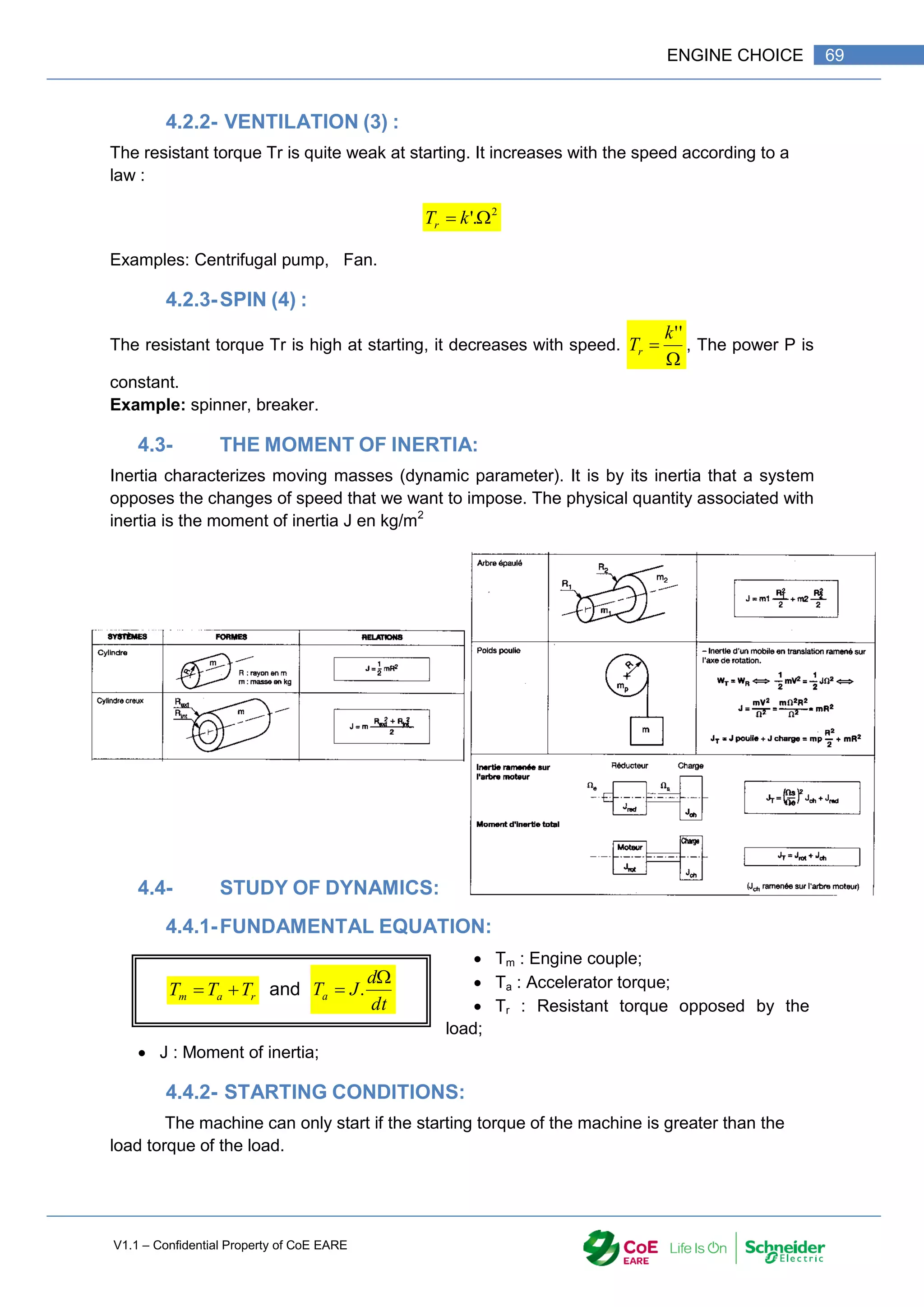
J : Moment of Inertia in kg/m2
;
We have to use the laws of mechanics to determine the parameters PU, m, Tm.
4.2- TYPE OF RESISTING TORQUE
The characteristic of the resistive torque as a function
of the speed defines the needs of the driven machine.
When this characteristic is not known, it is assimilated to
one of the three characteristics below.
4.2.1-PUMPING(1 AND 2):
The resistant torque Tr is quite strong at takeoff. It can be constant or grow slightly with
speed.
.
k
Tr Cte
Tr
Examples: Horizontal conveyor belt, lifting, Turbocharger.](https://image.slidesharecdn.com/iaindustrialautomation-part1-210930233627/75/Ia-industrial-automation-part-1-70-2048.jpg)
![V1.1 – Confidential Property of CoE EARE
70 [Industrial Automation – Part 1 Installation] [Safety and Security – Basic Industrial wiring]
Examples :
The engine starts Td > TR0 The engine doesn’t start Td < TR0
The acceleration is higher as : Tm is bigger tahn Tr and J is small.
4.4.3-RUNING AT OPERATING POINT):
n steady state the speed is constant. So the acceleration torque no longer exists.
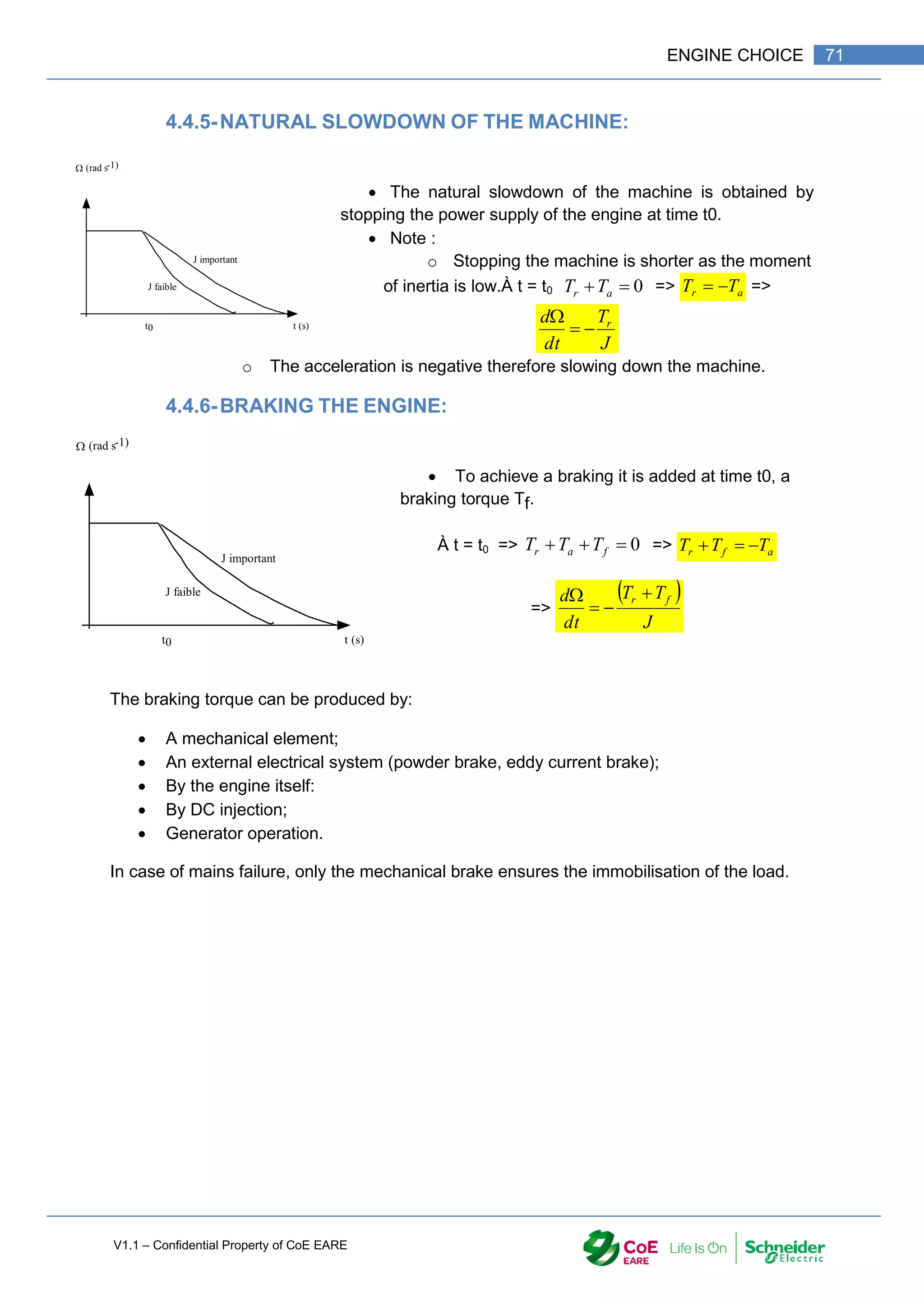
4.4.4-STABLE OPERATION OF THE MACHINE:
The stable operating point of the machine is the point
where the motor and resistive torque are equal.
Note:
The motor is generally chosen so that the operating point
A is as close as possible to the operation in nominal mode.
T (Nm)
Tm = f ()
(rad s-1)
Td
Tr = f ()
TR0
T (Nm)
Tm = f ()
(rad s-1)
Td
Tr = f ()
TR0
T (Nm)
Tm = f (V)
(rad s-1)
T
Tr = f ()
A
m
d T
T => r
m
a T
T
dt
d
J
T
.
Si cte
=> 0
dt
d
=> r
m T
T ](https://image.slidesharecdn.com/iaindustrialautomation-part1-210930233627/75/Ia-industrial-automation-part-1-72-2048.jpg)
![V1.1 – Confidential Property of CoE EARE
72 [Industrial Automation – Part 1 Installation] [Safety and Security – Basic Industrial wiring]
5- OPERATING QUADRANTS OF A MACHINE:
The working Quadrant are :
Motor : Q1 and Q3 (the engin provide a mechanic power)
Generator or Break; Q2 and Q4 (The engine is absorbing a mechanic power)
Direction Speed Torque Power Quadrant Work Load
Direction 1 +
+
+
-
+
-
1
2
Motor
Generator
Resistive
Leading
Direction 2 -
-
-
+
+
-
3
4
Motor
Generator
Resistive
Leading
6- OTHER CRITERIA FOR CHOOSING AN ELECTROMECHANICAL
CONVERTER:
6.1- CHOICE BASED ON THE ENVIRONMENT:
6.1.1-DECOMMISSIONING:
The normal conditions of use of standard machines are: a temperature between -16 ° C and
40 ° C; the altitude below 1000 m.
Corrections must be made outside these values.
𝑃𝑡𝑜 𝑖𝑛𝑠𝑡𝑎𝑙𝑙 = 𝑃𝐶𝑎𝑙𝑐𝑢𝑙𝑎𝑡𝑒𝑑 ∗
𝑃1
𝑃](https://image.slidesharecdn.com/iaindustrialautomation-part1-210930233627/75/Ia-industrial-automation-part-1-74-2048.jpg)
![V1.1 – Confidential Property of CoE EARE
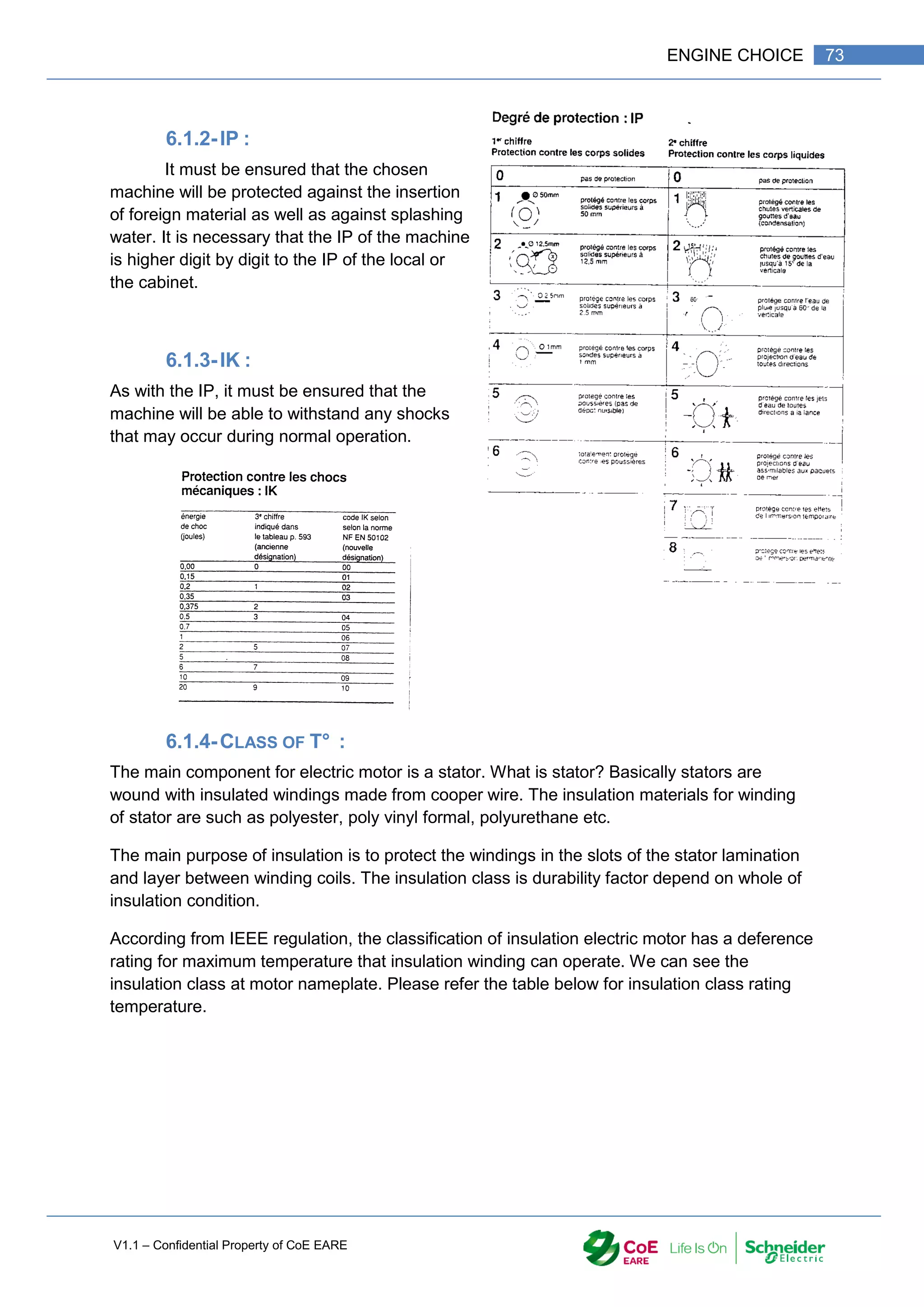
74 [Industrial Automation – Part 1 Installation] [Safety and Security – Basic Industrial wiring]
The windings of a machine are coated with a varnish that
deteriorates with high temperatures. The standard has defined
temperature isolation classes that ensure proper operation for at
least 105
hours.
In the case where the machine used would work with a temperature higher than that of its
class, it is necessary to correct the life of the machine using the table of thermal aging of the
insulators.
For an ambient temperature> 40 ° C, the machine is downgraded according to the following
coefficients:
𝑃𝑡𝑜 𝐼𝑛𝑠𝑡𝑎𝑙𝑙 = 𝑘 ∗ 𝑃𝑐𝑎𝑙𝑐𝑢𝑙𝑎𝑡𝑒𝑑
6.2- DUTY TYPES:
The choice of a machine is also conditioned by its operating conditions. Thus we define 8
"services" or Duty Types according to the operating conditions ('Start, Nominal operation,
idle operation, braking, stop).
In compliance with the classification of Std. IEC 60034-1 here are some indications regarding
the duty types which are typically considered as reference to indicate the rating of the motor.
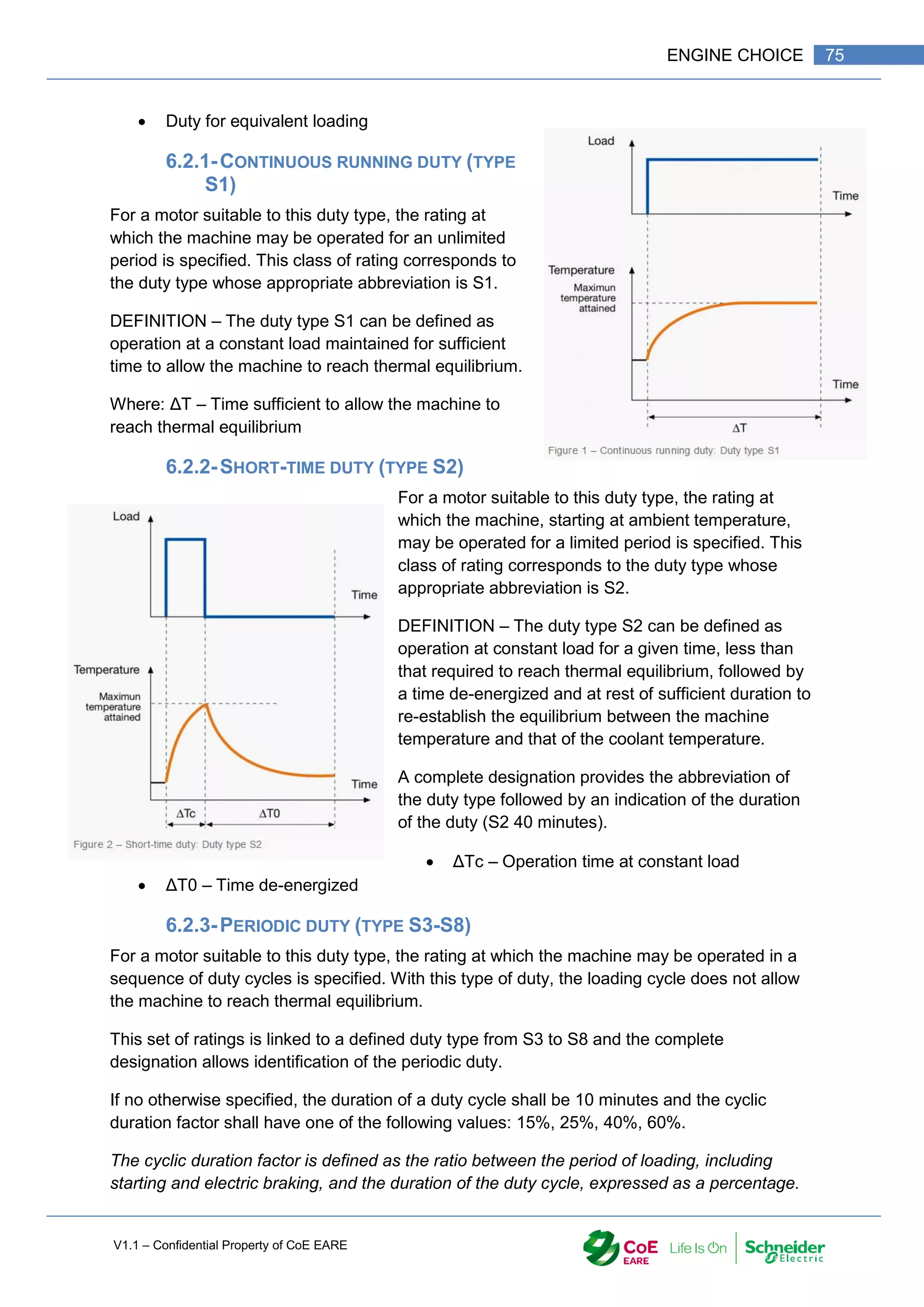
Continuous running duty (type S1)
Short-time duty (type S2)
Periodic duty (type S3-S8)
o Intermittent periodic duty (Type S3)
o Intermittent periodic duty with starting (Type S4)
o Intermittent periodic duty with electric braking (Type S5)
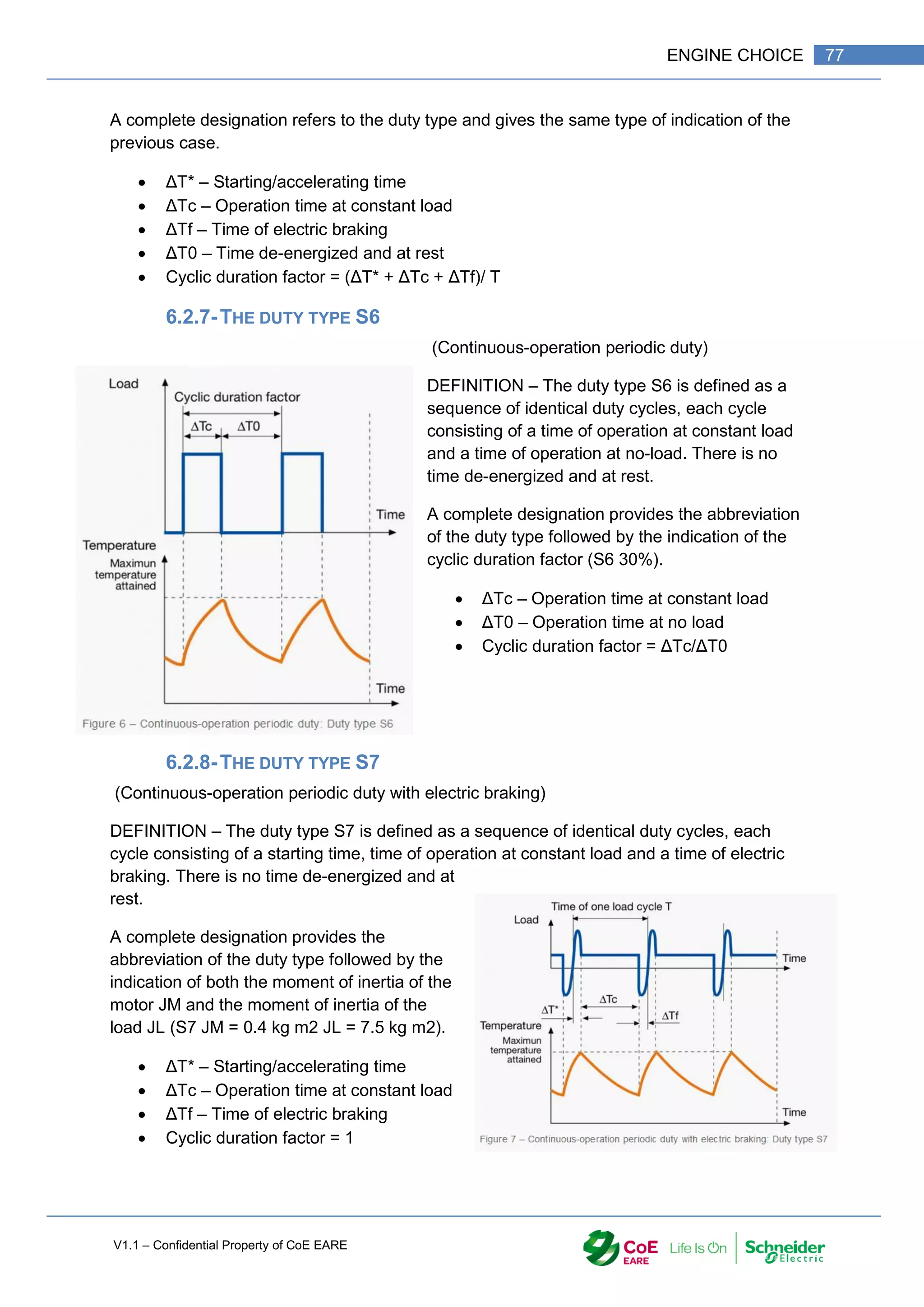
o Continuous-operation periodic duty (Type S6)
o Continuous-operation periodic duty with electric braking (Type S7)
o Continuous-operation periodic duty with related load / speed (Type S8)
Non-periodic duty (type S9)
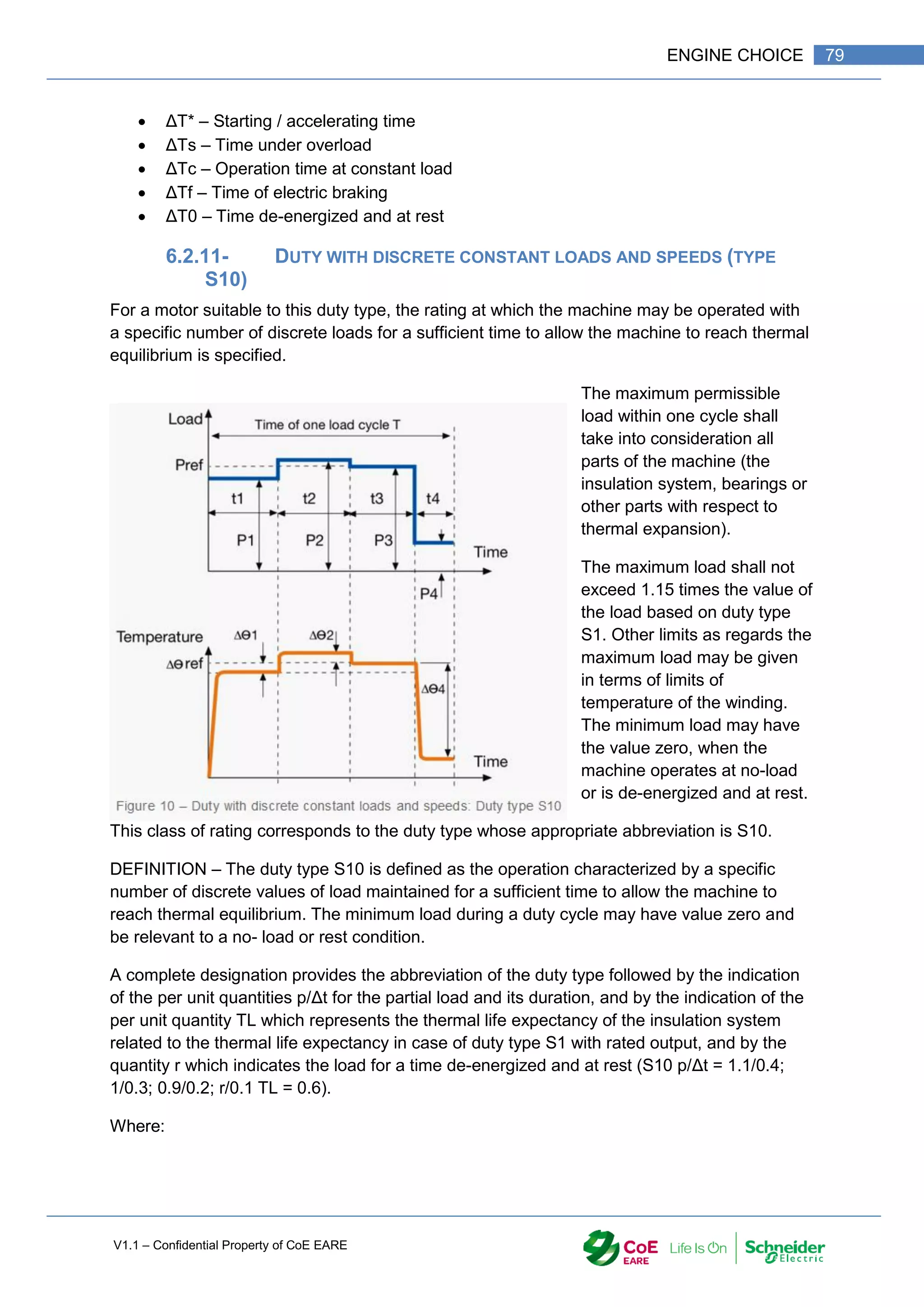
Duty with discrete constant loads (and speeds) – type S10
i k
45 °C 100/9
5
50 °C 100/9
0
55 °C 100/8
5](https://image.slidesharecdn.com/iaindustrialautomation-part1-210930233627/75/Ia-industrial-automation-part-1-76-2048.jpg)
![V1.1 – Confidential Property of CoE EARE
76 [Industrial Automation – Part 1 Installation] [Safety and Security – Basic Industrial wiring]
6.2.4-DUTY TYPE S3
(Intermittent periodic duty)
DEFINITION – The duty type S3 is defined as a
sequence of identical duty cycles, each including a time
of operation at constant load and a time de-energized
and at rest. The contribution to the temperature-rise
given by the starting phase is negligible.
A complete designation provides the abbreviation of the
duty type followed by the indication of the cyclic
duration factor (S3 30%).
ΔTc – Operation time at constant load
ΔT0 – Time de-energized and at rest
Cyclic duration factor = ΔTc/T
6.2.5-THE DUTY TYPE S4
(Intermittent periodic duty with starting)
DEFINITION – The duty type S4 is defined as a
sequence of identical duty cycles, each cycle
including a significant starting time, a time of
operation at constant load and a time de-
energized and at a rest.
A complete designation provides the
abbreviation of the duty type followed by the
indication of the cyclic duration factor, by the
moment of inertia of the motor JM and by the
moment of inertia of the load JL, both referred to
the motor shaft (S4 20% JM = 0.15 kg m2 JL =
0.7 kg m2).
ΔT* – Starting/accelerating time
ΔTc – Operation time at constant load
ΔT0 – Time de-energized and at rest
Cyclic duration factor = (ΔT* + ΔTc)/ T
6.2.6-THE DUTY TYPE S5
(Intermittent periodic duty with electric braking)
DEFINITION – The duty type S5 is defined as a
sequence of identical duty cycles, each cycle
consisting of a starting time, a time of operation
at constant load, a time of electric braking and a
time de-energized and at a rest.](https://image.slidesharecdn.com/iaindustrialautomation-part1-210930233627/75/Ia-industrial-automation-part-1-78-2048.jpg)
![V1.1 – Confidential Property of CoE EARE
78 [Industrial Automation – Part 1 Installation] [Safety and Security – Basic Industrial wiring]
6.2.9-THE DUTY TYPE S8
(Continuous-operation periodic duty with related load / speed)
DEFINITION – The duty type S8 is defined as a sequence of identical duty cycles, each
consisting of a time of operation at constant load corresponding to a predetermined speed of
rotation, followed by one or more times of operation at other constant loads corresponding to
different speeds of rotation.
There is no time de-energized and at rest.
A complete designation
provides the abbreviation of
the duty type followed by the
indication of the moment of
inertia of the motor JM and by
the moment of inertia of the
load JL, together with the
load, speed and cyclic
duration factor, for each
speed condition (S8 JM = 0.7
kg m2 JL = 8kgm2 25kW
800rpm 25% 40kW 1250rpm
20% 25 kW 1000 rpm 55%).
ΔT* – Starting/accelerating time
ΔTc1; ΔTc2; ΔTc3 – Operation time at constant load
ΔTf1; ΔTf2 – Time of electric braking
Cyclic duration factor = (ΔT*+ΔTc1)/T; (ΔTf1+ΔTc2)/T; (ΔTf2+ΔTc3)/T
6.2.10- NON-PERIODIC DUTY (TYPE S9)
Duty with non-periodic load and speed variations
For a motor suitable to this duty type, the rating at which the machine may be operated non-
periodically is specified. This
class of rating corresponds to
the duty type whose
appropriate abbreviation is
S9.
DEFINITION – The duty type
S9 is defined as a duty in
which generally load and
speed vary non-periodically
within the permissible
operating range. This duty
includes frequently appplied
overloads which may greatly
exceed the reference load.](https://image.slidesharecdn.com/iaindustrialautomation-part1-210930233627/75/Ia-industrial-automation-part-1-80-2048.jpg)
![V1.1 – Confidential Property of CoE EARE
80 [Industrial Automation – Part 1 Installation] [Safety and Security – Basic Industrial wiring]
ΔΘ1; ΔΘ2; ΔΘ2 – Difference between the temperature rise of the winding at each of
the various loads within one cycle and the temperature rise based on duty cycle S1
with reference load
ΔΘref – Temperature at reference load based on duty type S1 t1; t2; t3; t4: time of a
constant load within a cycle P1; P2; P3; P4: time of one load cycle
(Pref: reference load based on duty type S1)
6.2.12- DUTY FOR EQUIVALENT LOADING
For a motor suitable to this duty type, the rating, for test purposes, at which the machine may
be operated at constant load until thermal equilibrium is reached and which results in the
same stator winding temperature rise as the average temperature rise during one load cycle
of the specified duty type.
This class of ratings, if applied, corresponds to the duty type designated “equ”.
6.3- GEOMETRIC CRITERIA:
The size of the machine can in some cases cause problems. We must therefore
check the position (horizontal or vertical) and the dimensions of the machine.](https://image.slidesharecdn.com/iaindustrialautomation-part1-210930233627/75/Ia-industrial-automation-part-1-82-2048.jpg)
![V1.1 – Confidential Property of CoE EARE
82 [Industrial Automation – Part 1 Installation] [Safety and Security – Basic Industrial wiring]
DC MOTOR](https://image.slidesharecdn.com/iaindustrialautomation-part1-210930233627/75/Ia-industrial-automation-part-1-84-2048.jpg)
![V1.1 – Confidential Property of CoE EARE
84 [Industrial Automation – Part 1 Installation] [Safety and Security – Basic Industrial wiring]
E R I
U
E’ R I
U
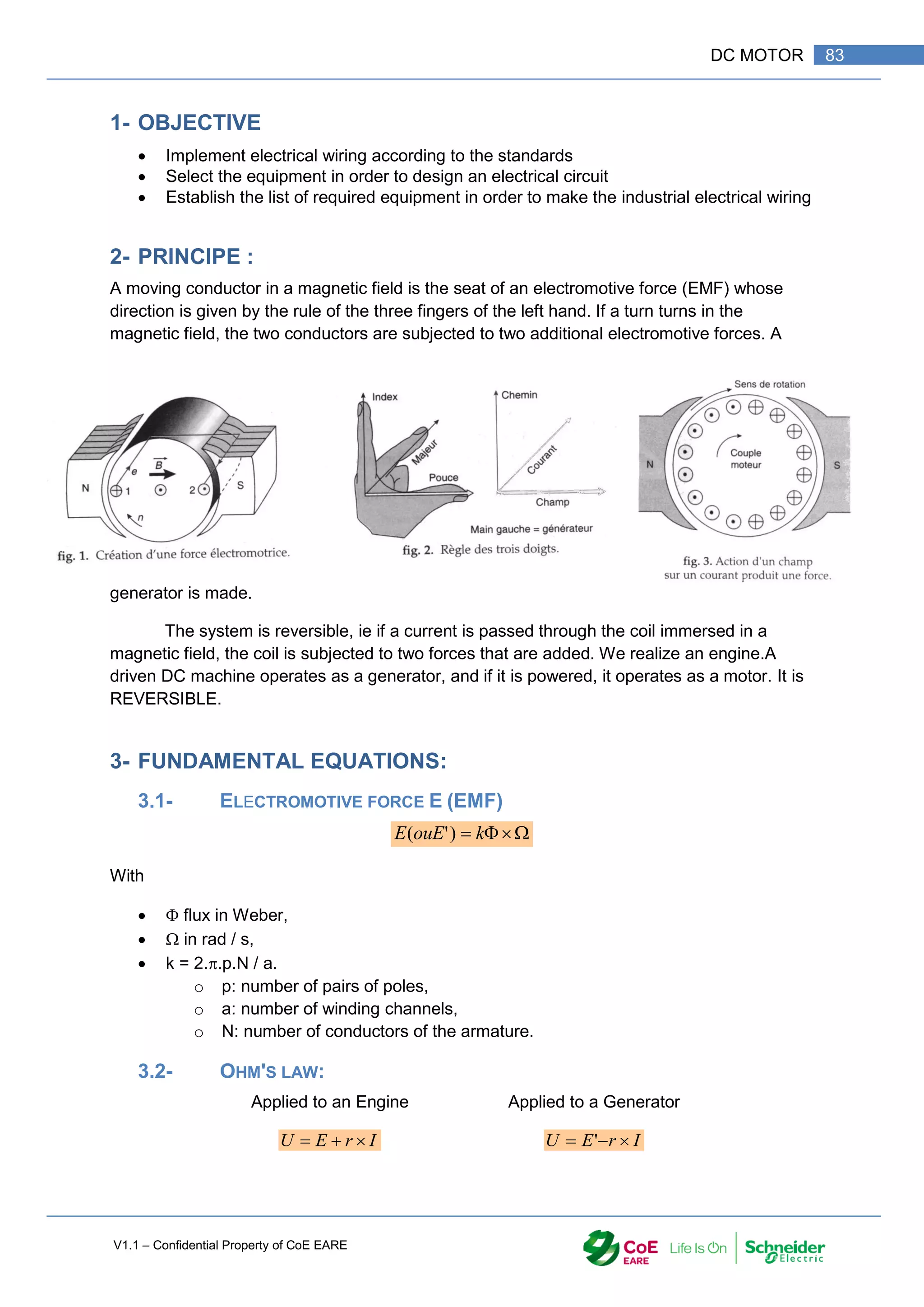
With E electromotive force,
E 'force against electromotive
R resistance of the armature
I current in the armature.
3.3- SPEED
Using previous relationships
For an engine For a generator.
k
I
r
U
k
I
r
U
3.4- THE POWER :
I
E
P
or I
E
P
'
3.5- ENGINE TORQUE :
I
k
P
T
4- CONSTRUCTION :
The DC machine consists mainly of:
o A magnetic circuit to channel the flow;
o An inductive electric circuit to produce the flux and an induced electric circuit;
o A mechanical part to fix the different elements with respect to each other.
4.1- THE MAGNETIC CIRCUIT:
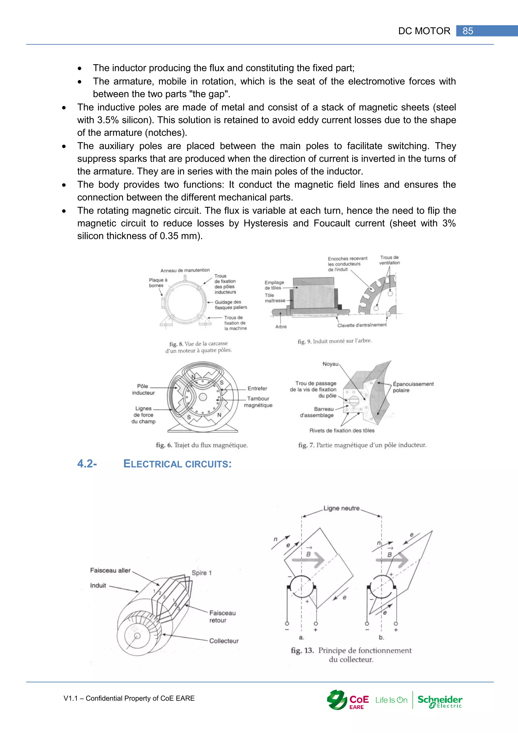
It consists of two parts:](https://image.slidesharecdn.com/iaindustrialautomation-part1-210930233627/75/Ia-industrial-automation-part-1-86-2048.jpg)
![V1.1 – Confidential Property of CoE EARE
86 [Industrial Automation – Part 1 Installation] [Safety and Security – Basic Industrial wiring]
4.2.1-THE INDUCTOR:
It creates the magnetic flux in the main poles. The excitation power is about 2 to 3% of the
total power (5% for small machines).
The excitation winding can be shunted (or shunt (large number of turns in fine wires)) or in
series (small number of coils in thick wire) with the armature.
4.2.2-THE ARMATURE:
The winding of the armature is composed of a large number of sections formed of turns
whose ends are connected to two consecutive blades of the commutator.
4.2.3-THE COMMUTATOR:
It provides the connection between the rotating conductors and the external circuit. It
transforms the alternating current of the armature into direct current.
Crossing the neutral line, the commutator reverses the polarity of the conductors so that the
forces are always in the same direction.
The connection is made by graphite brushes which must be monitored for wear.
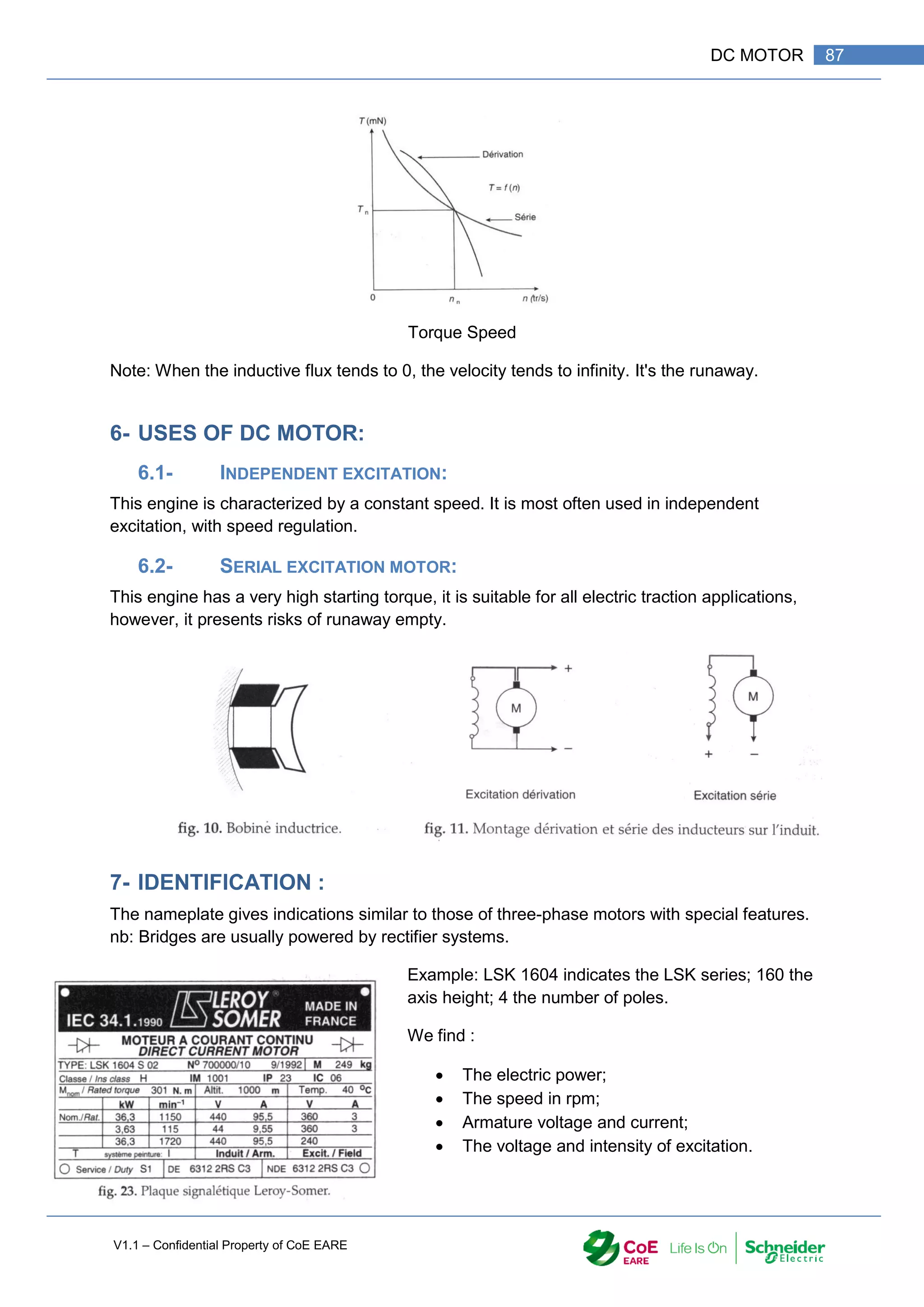
5- CHARACTERISTICS :
The DC machine is characterized by:
The nominal power of operation;
The armature voltage;
The speed of rotation;
The couple;
The power supply of the inductive circuit.
Characteristics of the operation according to the power supply of the inductor:
Current Speed: Current Torque:](https://image.slidesharecdn.com/iaindustrialautomation-part1-210930233627/75/Ia-industrial-automation-part-1-88-2048.jpg)
![V1.1 – Confidential Property of CoE EARE
88 [Industrial Automation – Part 1 Installation] [Safety and Security – Basic Industrial wiring]
8- STARTING A DC MOTOR:
At power up, the motor does not rotate so the electromotive force is zero. The called current
is limited only by armature resistance. This results in a strong
starting current. To limit this current between 1.2 and 2 In, the
resistor is placed in series with the armature.
Contactor starter:
Km1: forward;
Km2: reverse,
K1 and K2 start contactor.
When starting a DC motor in Seri wiring, do not under any circumstances cut the excitation
before the armature.
9- EXERCICE :
A passenger transport system requires a DC motor to meet the specifications. It must
provide a torque of 58 Nm for a speed of 900 rpm.
Q 1. Calculate the useful power that the engine must supply. Look for the
characteristics of this engine in the course documentation.
Q 2. Give the model of the course the nameplate of the engine.
Q 3. We want a starting current of 2 In maximum. Calculate the starting resistances. We
will take k = 3.385.
Q 4. The motor is controlled by contactors. It works in both directions of rotation. Give
the power scheme for this operation. Using the telemechanical documents, look for
the reference of the different constituents of the power circuit.](https://image.slidesharecdn.com/iaindustrialautomation-part1-210930233627/75/Ia-industrial-automation-part-1-90-2048.jpg)

![V1.1 – Confidential Property of CoE EARE
90 [Industrial Automation – Part 1 Installation] [Safety and Security – Basic Industrial wiring]
1- OBJECTIVE
Implement electrical wiring according to the standards
Select the equipment in order to design an electrical circuit
Establish the list of required equipment in order to make the industrial electrical wiring
2- INTRODUCTION
An induction motor or asynchronous motor is an AC electric motor in which the electric
current in the rotor needed to produce torque is obtained by electromagnetic induction from
the magnetic field of the stator winding. An induction motor can therefore be made without
electrical connections to the rotor. An induction motor's rotor can be either wound type or
squirrel-cage type.
Three-phase squirrel-cage induction motors are widely used as industrial drives because
they are rugged, reliable and economical. Single-phase induction motors are used
extensively for smaller loads, such as household appliances like fans. Although traditionally
used in fixed-speed service, induction motors are increasingly being used with variable-
frequency drives (VFDs) in variable-speed service. VFDs offer especially important energy
savings opportunities for existing and prospective induction motors in variable-torque
centrifugal fan, pump and compressor load applications. Squirrel cage induction motors are
very widely used in both fixed-speed and variable-frequency drive (VFD) applications.
The conversion of electrical energy is 80% by three-phase asynchronous motors thanks to
their simplicity of conversion, their robustness and their ease of starting.](https://image.slidesharecdn.com/iaindustrialautomation-part1-210930233627/75/Ia-industrial-automation-part-1-92-2048.jpg)
![V1.1 – Confidential Property of CoE EARE
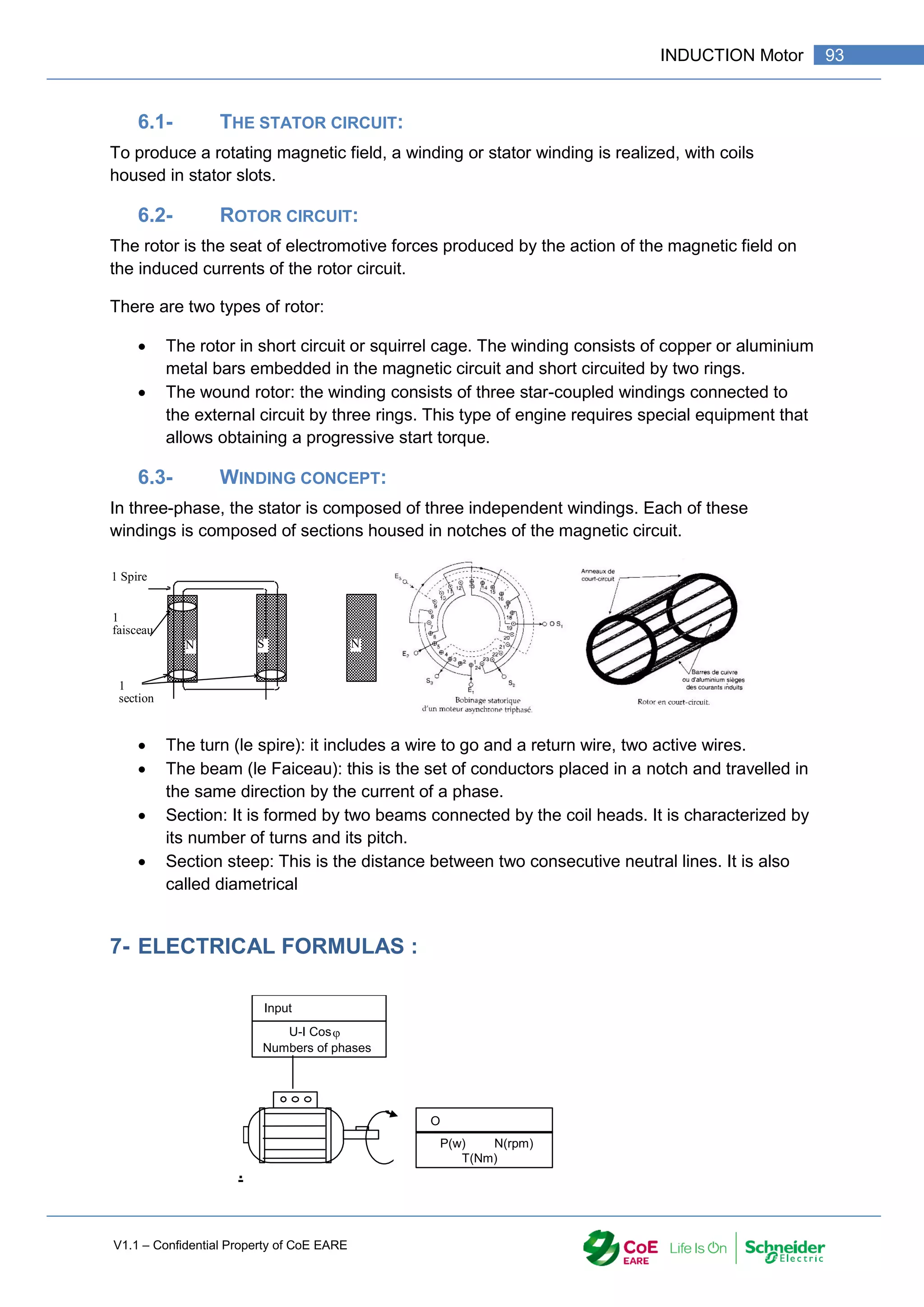
92 [Industrial Automation – Part 1 Installation] [Safety and Security – Basic Industrial wiring]
An induction motor can be used as an induction generator, or it can be unrolled to form a
linear induction motor which can directly generate linear motion.
5- PRINCIPLE OF OPERATION OF THE ASYNCHRONOUS
MACHINE:
5.1- CREATING A ROTATING FIELD:
If three identical coils placed at 120 ° are
fed by a three-phase AC voltage:
A magnetized needle, placed in the
center, is rotated; So there is a creation of a
rotating field.
The needle is replaced by a metal disc
made of aluminum or copper. It is driven in the
same direction as the magnetic needle.
If two of the three three-phase power
leads are reversed, the needle or disc rotates in
the opposite direction.Principe de fonctionnement
de la machine asynchrone :
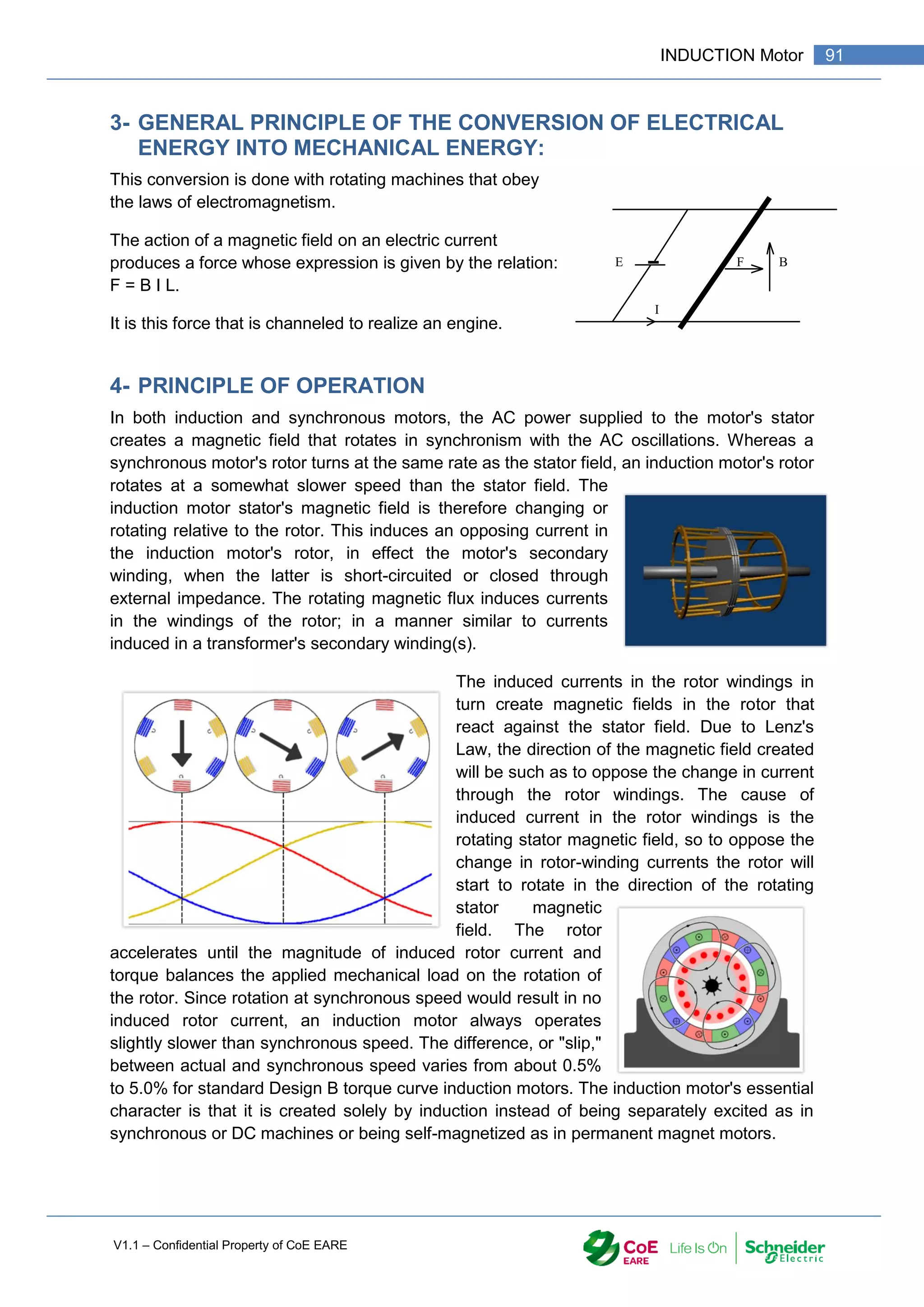
The three AC fields produced by the three-phase-fed coils are composed to form a rotating
field. The rotating magnetic field creates induced currents in the metal disk; These, according
to Lenz's law, oppose the cause that gave rise to them, and cause a magnetomotive force
that drives the disk in rotation.
The part containing the coils creating the magnetic field is called "STATOR". The moving part
under the influence of the magnetic field is called "ROTOR".
6- CONSTITUTION OF AN ASYNCHRONOUS MACHINE:](https://image.slidesharecdn.com/iaindustrialautomation-part1-210930233627/75/Ia-industrial-automation-part-1-94-2048.jpg)
![V1.1 – Confidential Property of CoE EARE
94 [Industrial Automation – Part 1 Installation] [Safety and Security – Basic Industrial wiring]
The asynchronous motor transforms the electrical energy supplied by the single-phase or
three-phase alternating current into mechanical energy. It is characterized by input quantities
that are electrical and by output quantities that are mechanical.
The electrical power absorbed by a three-phase asynchronous motor is:
Pa: Power in W (Watt); U: Voltage in V (Volts); I: Current in A (Amperes);
Cos : cosine of the phase shift angle between current and voltage.
Note: The current and voltage measurements can not give the power, Cos can vary
between 0.1 and 0.2 empty until 0.9 at full load.
The mechanical power is that obtained on the motor shaft:
Pu: Power in W (watt); Tu: Engine torque Newton-meter (Nm);
: angular velocity in radians per second (rad / s); n: Rotational speed in revolutions per second (rps).
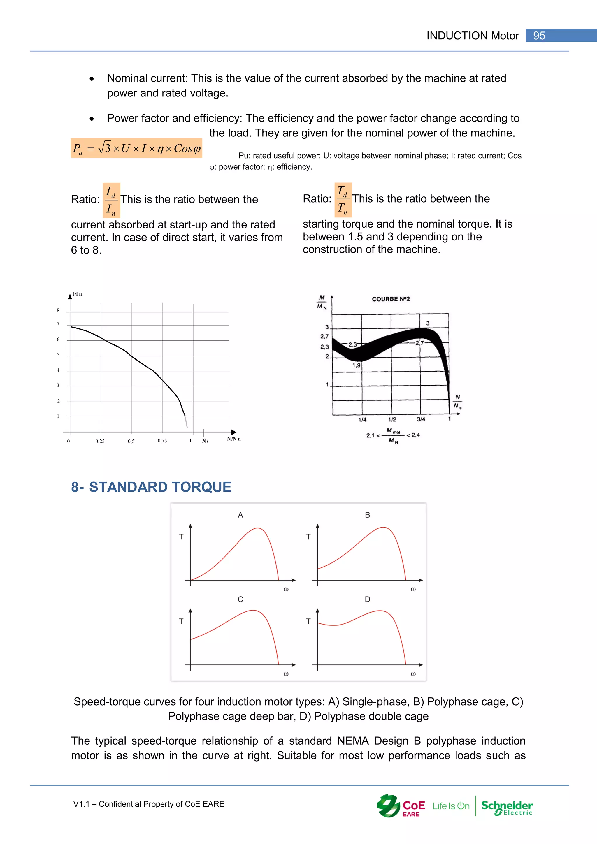
Rated power: This is the mechanical power available on the motor shaft at its rated
speed.
Rated speed: The nominal speed is the speed at nominal power. We distinguish the
speed of synchronism (speed of the rotating field):
Where f is the frequency of the power supply, p is the number of magnetic poles, and ns is
the synchronous speed of the machine. For f in Hertz and ns in RPM, the formula becomes:
Slip, s is defined as the difference between synchronous speed and operating speed,
at the same frequency, expressed in rpm, or in percentage or ratio of synchronous
speed. Thus
Where ns is stator electrical speed, nr is rotor
mechanical speed.
Slip, which varies from zero at synchronous speed
and 1 when the rotor is at rest, determines the
motor's torque.
Cos
I
U
Pa
3
u
u T
P](https://image.slidesharecdn.com/iaindustrialautomation-part1-210930233627/75/Ia-industrial-automation-part-1-96-2048.jpg)
![V1.1 – Confidential Property of CoE EARE
96 [Industrial Automation – Part 1 Installation] [Safety and Security – Basic Industrial wiring]
centrifugal pumps and fans, Design B motors are constrained by the following typical torque
ranges:
Breakdown torque (peak torque), 175-300% of rated torque
Locked-rotor torque (torque at 100% slip), 75-275% of rated torque
Pull-up torque, 65-190% of rated torque.
Over a motor's normal load range, the torque's slope is approximately linear or proportional
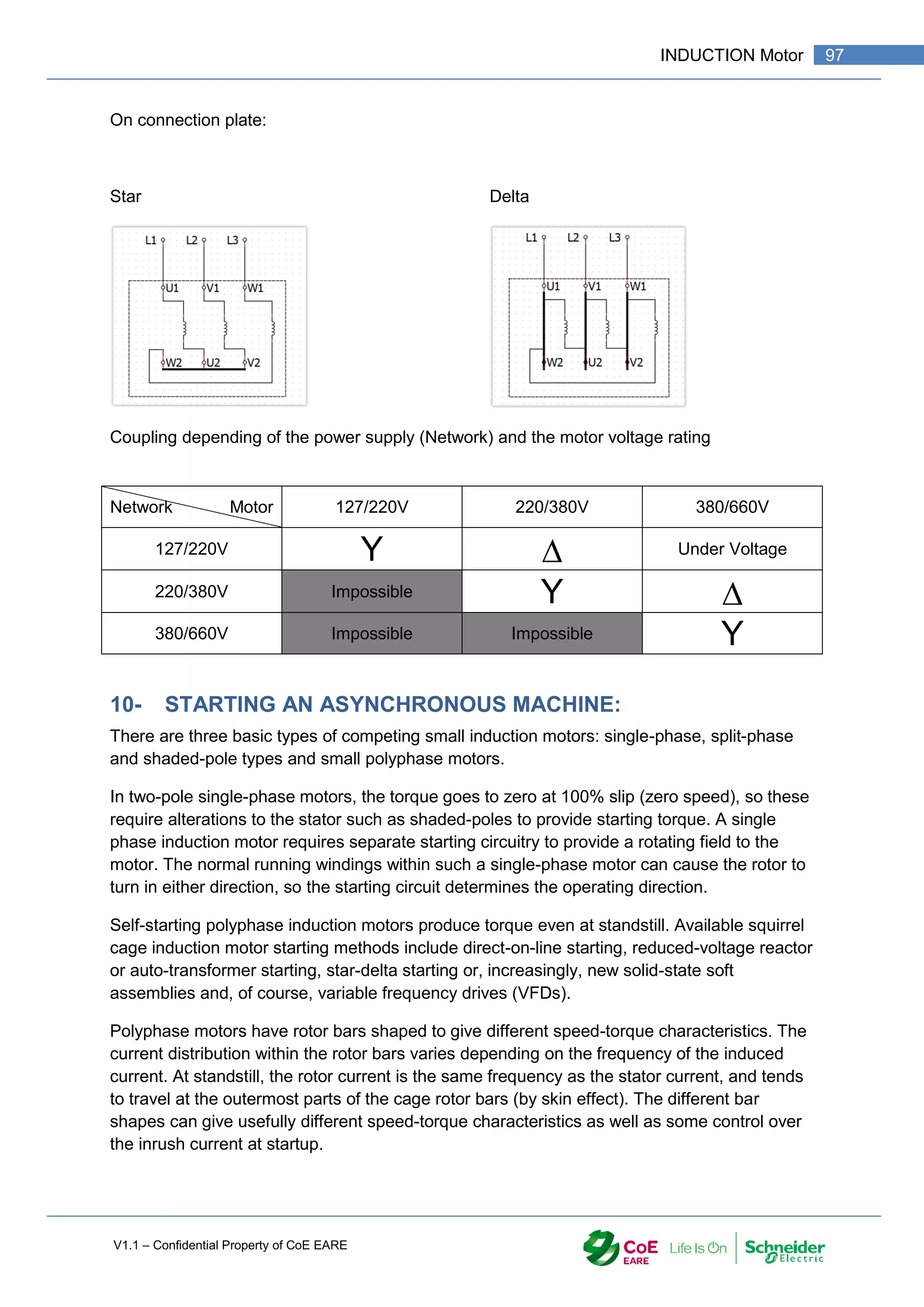
9- COUPLING
Induction motor is composed of three coils. One coil per phase. Each coil has a nominal
voltage and nominal current. These values are written on the rating plate of the motor.
The voltage of the power supply is important to know as it will define what will be the
coupling of the motor. An Induction Motor has two voltages with a ratio of √3. E.g. 220/380V
The lowest voltage is the maximum voltage a coil can handle. In this case, the voltage of the
power supply in important to know. For a power supply of 220/380V, the voltage between
phases is 380V.
There are two types of connection (coupling) for an induction motor:
Star, on end of the three coils are
connected together.
o U2, V2, W2 connected
together,
o Power supply on U1, V1,
W1.
Delta, all coils are in series.
o U1 connected to W2
o W1 connected to V2
o V1 connected to U2](https://image.slidesharecdn.com/iaindustrialautomation-part1-210930233627/75/Ia-industrial-automation-part-1-98-2048.jpg)
![V1.1 – Confidential Property of CoE EARE
98 [Industrial Automation – Part 1 Installation] [Safety and Security – Basic Industrial wiring]
In wound rotor motors, rotor circuit connection through slip rings to external resistances
allows change of speed-torque characteristics for acceleration control and speed control
purposes.
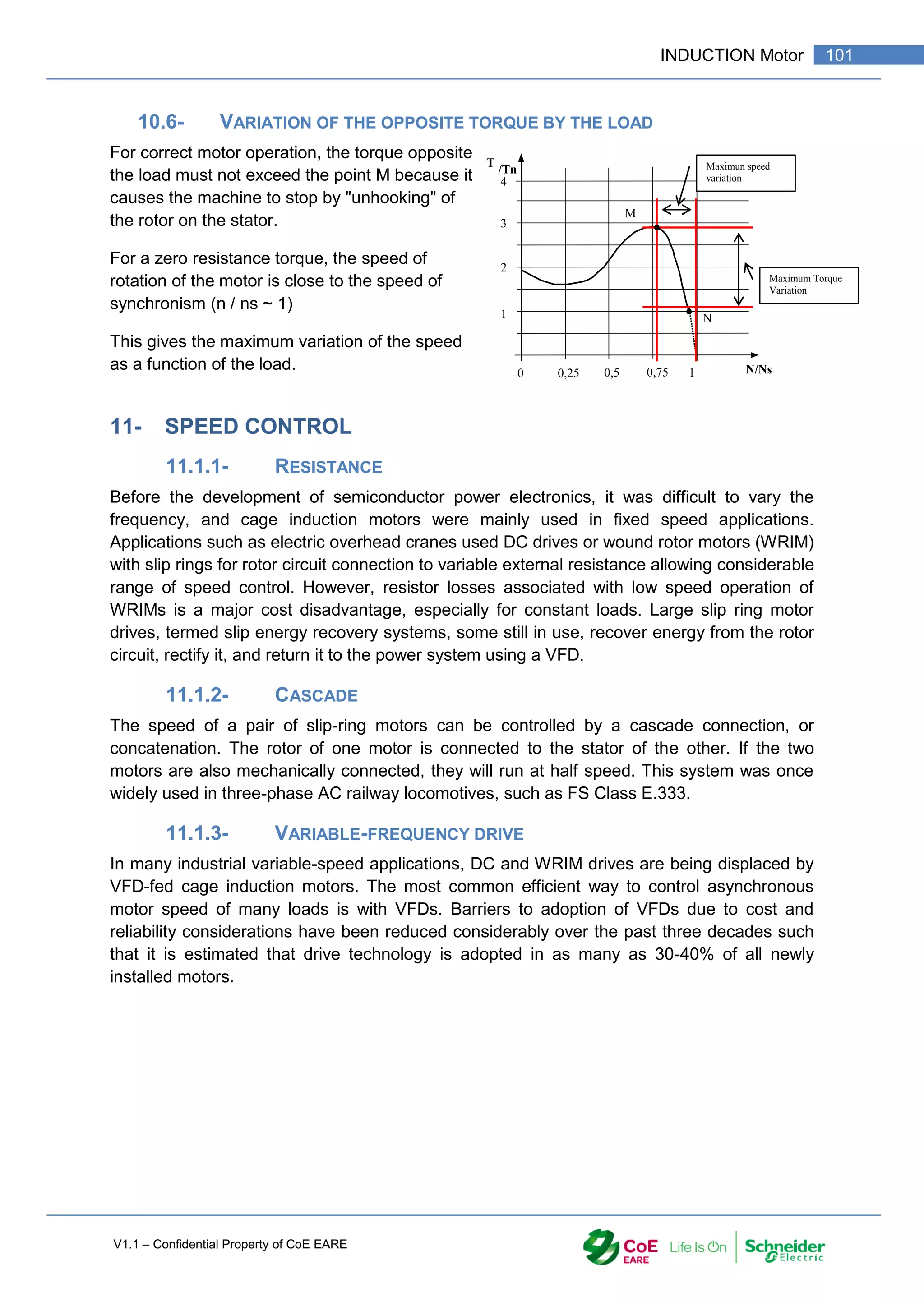
10.1- CASE OF THE STARTING TORQUE:
For an Induction Motor to start, the torque
demanded by the load on startup must be less
than the starting torque of the machine.
The machine produces the starting and stabilizes
at the point F which is the point of operation of
the system.
This point must be as close as possible to point
N (nominal point of the machine) to obtain
maximum energy efficiency.
10.2- DIRECT ON LINE :
Direct startup of an asynchronous machine causes a high starting current. Id = 6 to 8
In.
Make sure that the protections are not tripped: fuse use aM.
To avoid the disadvantage of the fuse aM (melting delay), the motor is protected
against overloads by a thermal tripping device
10.3- STAR – DELTA STARTING :
This type of startup avoids the disadvantage of the strong
current at startup. Indeed by using a reduced voltage at
startup, the current is limited.
3
d
d
I
I
3
d
d
T
T
The disadvantage lies in the weakness of the
starting torque.
Star Delta Starter can only be used if the starter-
resistant torque is zero or very low.
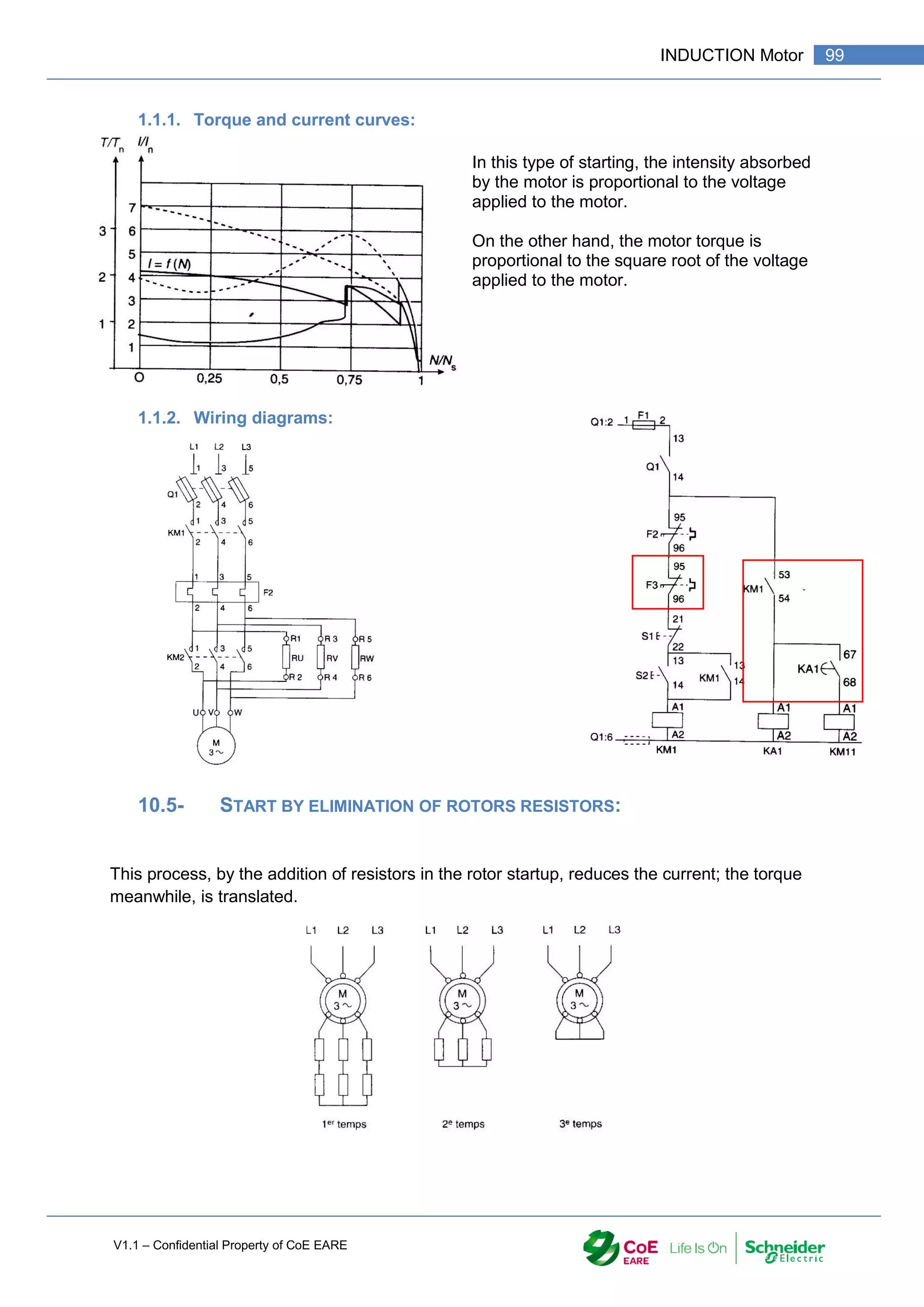
10.4- STATOR STARTER : STARTING BY ELIMINATING STATOR RESISTORS:
Always to eliminate the intensity peak at startup, work under
reduced voltage. This reduced voltage is achieved by
inserting stator resistors in series with the motor. We can
achieve a start in several times.
0
T
/Tn
1
2
3
4
0,25 0,5 0,75 N/Ns
Couple résistant
opposé par la charge
Couple Moteur
1
F
N](https://image.slidesharecdn.com/iaindustrialautomation-part1-210930233627/75/Ia-industrial-automation-part-1-100-2048.jpg)
![V1.1 – Confidential Property of CoE EARE
100 [Industrial Automation – Part 1 Installation] [Safety and Security – Basic Industrial wiring]
10.5.1- TORQUE AND CURRENT CURVES:
This type of start allows for a lower absorbed current to obtain a torque at the start.
10.5.2- WIRING DIAGRAMS](https://image.slidesharecdn.com/iaindustrialautomation-part1-210930233627/75/Ia-industrial-automation-part-1-102-2048.jpg)
![V1.1 – Confidential Property of CoE EARE
102 [Industrial Automation – Part 1 Installation] [Safety and Security – Basic Industrial wiring]
Typical speed-torque curves for different motor input frequencies as for example used with
variable-frequency drives
12- IN SUMMARY
Starter Direct Star Delta Stator Rotor
Initial current 4 to 8 In 1,3 to 2,6 In 4,5 In 2,5 In
Staring Torque 0,6 to 1,5 Tn 0,2 to 1,5 Tn 0,6 to 9,85 Tn 2,5 Tn
Average
duration
2 to 3 s 3 to 7 s 7 to 12 s 2,5 to 5 s
Advantages Simple and
costless starter
High starting
torque
Good ratio
Torque / Curent
Not too
expensive
No supply cut,
limitation of
Inrush current
Very good ration
Torque/Current
No power cut
Disadvantage High Inrush
current
Strong stating
Small staring
Torque, Power
cut when
changing from
Star to Delta
Need of
resistances
Small reduction
of the Inrush
Current
Winding Rotor
more expensive
Nedd of
resistances
Applications Small motor
power up to
5KW
Induction motor
starting without
loads
Engin with high
Inertia
Progressive
starting
Lift](https://image.slidesharecdn.com/iaindustrialautomation-part1-210930233627/75/Ia-industrial-automation-part-1-104-2048.jpg)
![V1.1 – Confidential Property of CoE EARE
104 [Industrial Automation – Part 1 Installation] [Safety and Security – Basic Industrial wiring]
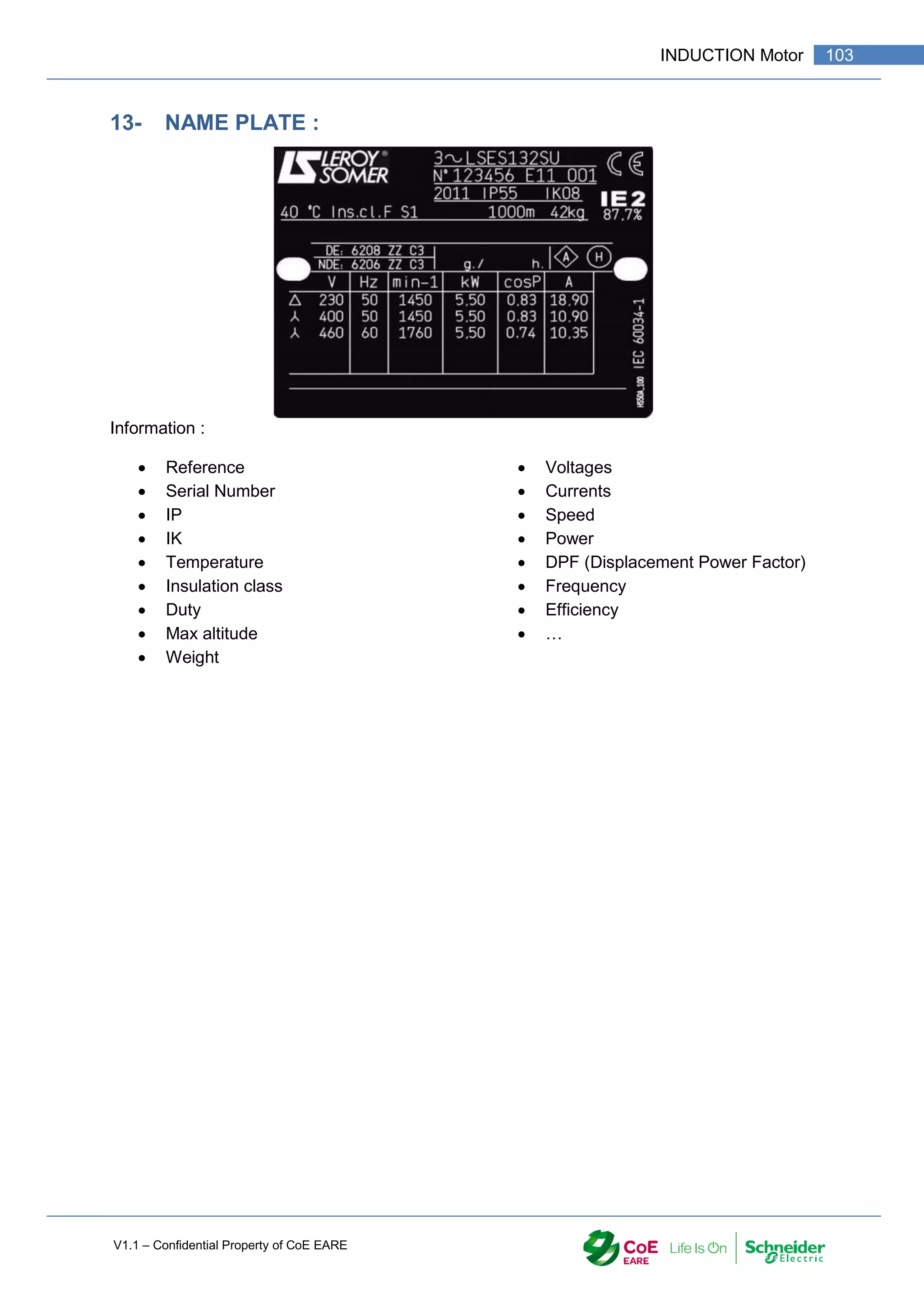
14- EXAMPLE OF INDUCTION MOTOR](https://image.slidesharecdn.com/iaindustrialautomation-part1-210930233627/75/Ia-industrial-automation-part-1-106-2048.jpg)
![V1.1 – Confidential Property of CoE EARE
106 [Industrial Automation – Part 1 Installation] [Safety and Security – Basic Industrial wiring]
15- MOTOR MOUNTING CODES
Proper motor installation and mounting position is essential in obtaining top-quality operation,
efficient performance, and maximum reliability. Sometimes, however, there is confusion
about the many different ways a motor can be installed.
There are two different standards—NEMA and IEC— which you will see when looking at
electric motor mounting positions. Although they are generally comparable, there are slight
differences between the two.
The standard IEC mounting position places the junction box on the top of the motor, known
as the IM B3 mounting position in IEC frame (or F3 in NEMA frames). On the other hand,
the NEMA standard mounting position is referred to as F1, with the junction/conduit box
located on the left side of the motor facing the output shaft.
The design of most motors is such that they can usually be operated in many mounting
positions, unless indicated otherwise. Some mounting positions, however, require additional
construction modifications to achieve optimal performance. For example, shaft-up or shaft-
down outdoor applications may require drilling of additional drain holes, drip covers and
stronger bearings to support heavy loads. Don't just assume you can bolt any motor in any
orientation!](https://image.slidesharecdn.com/iaindustrialautomation-part1-210930233627/75/Ia-industrial-automation-part-1-108-2048.jpg)
![V1.1 – Confidential Property of CoE EARE
108 [Industrial Automation – Part 1 Installation] [Safety and Security – Basic Industrial wiring]
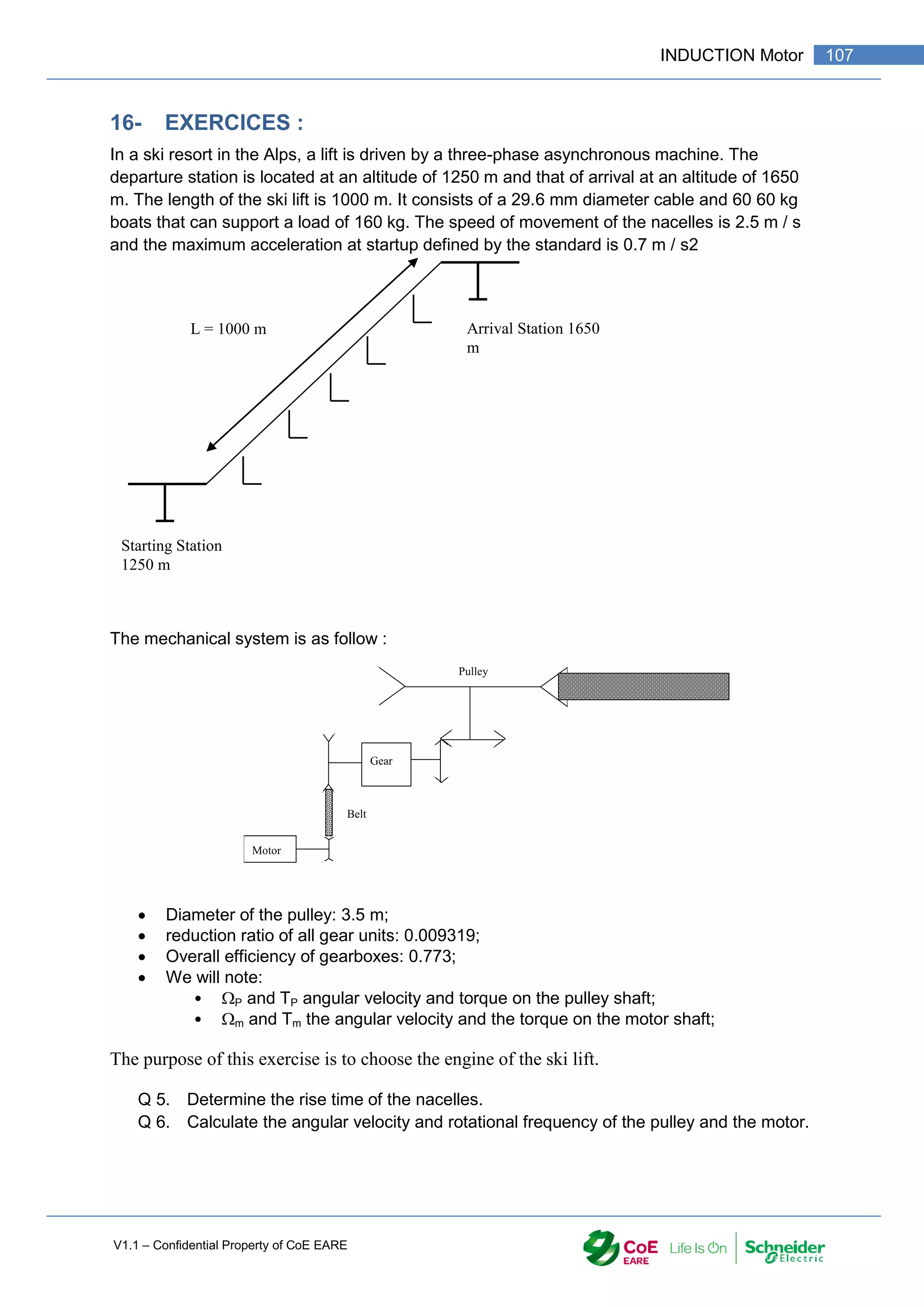
Q 7. Knowing that the torque opposite the load on the pulley is 33 160 N.m in steady
state, calculate the resisting torque on the motor shaft.
Q 8. Deduce the mechanical power that must provide the engine in steady state.
Q 9. The maximum acceleration allowed for passenger transport is 0.7 m / s2. Calculate
the angular acceleration (d/dt) on the pulley shaft and then on the motor shaft.
Q 10. Knowing that the total moment of inertia of the system brought back on the motor
shaft is 9.16 kg.m2, calculate the accelerating torque necessary to meet the
specifications. Deduce the minimum starting torque of the machine. Calculate then
ratio Cd / Cn.
Q 11. The maximum temperature of the room in which the motor is located is 30 ° C.
Check if corrections are needed for the choice of engine.
Q 12. Using the above calculations, knowing that the power supply is three-phase 3 *
400 V 50 Hz, select the motor in the LEROY SOMER documents.
Q 13. Give the nameplate of this engine.
Q 14. What should be the coupling of the windings?
Q 15. Calculate the starting current of the motor. What precautions should be taken?
Q 16. Give the maximum value of the torque and its value at startup.
Q 17. Give the outside dimensions of the engine.
Q 18. In steady state, determine the stable operating point of the motor. We will assume
the constant torque. Deduce the value of the slip and the speed of the nacelles.
Q 19. The torque can actually vary from 300 to 600 N.m. Give the theoretical variation
range of the motor rotation frequency.
Q 20. To avoid a sudden start, it is desired to use a soft start device. What types of
startup can I use? Justify your answer.](https://image.slidesharecdn.com/iaindustrialautomation-part1-210930233627/75/Ia-industrial-automation-part-1-110-2048.jpg)

![V1.1 – Confidential Property of CoE EARE
110 [Industrial Automation – Part 1 Installation] [Safety and Security – Basic Industrial wiring]
1- OBJECTIVE
Drawing and electrical circuit according to the standards
Implement electrical wiring according to the standards
Select the equipment in order to design an electrical circuit
Establish the list of required equipment in order to make the industrial electrical wiring
2- PREAMBLE :
The speed variation of electric machines is more and more used. Advances in power
electronics open up interesting prospects.
The operating principle can be represented according to the following diagram:
The setpoint is the control variable of the drive.
Variateur M
Réseau
Consigne
n
Consigne
3- VARIATION OR REGULATION:
3.1- DRIVER:
Allows variable speed without guaranteeing stability over
time;
During operation elements may vary:
The resistant torque;
The network voltage;
The temperature;
And cause a change in the actual speed compared to the setpoint.
The speed variation is poorly adapted to low speeds.
3.2- CONTROLER :
Maintains the actual speed in accordance with a very
small deviation from the set speed despite
disturbances;
To do this, the controller must be constantly informed
of the actual speed of the motor via a speed sensor..](https://image.slidesharecdn.com/iaindustrialautomation-part1-210930233627/75/Ia-industrial-automation-part-1-112-2048.jpg)
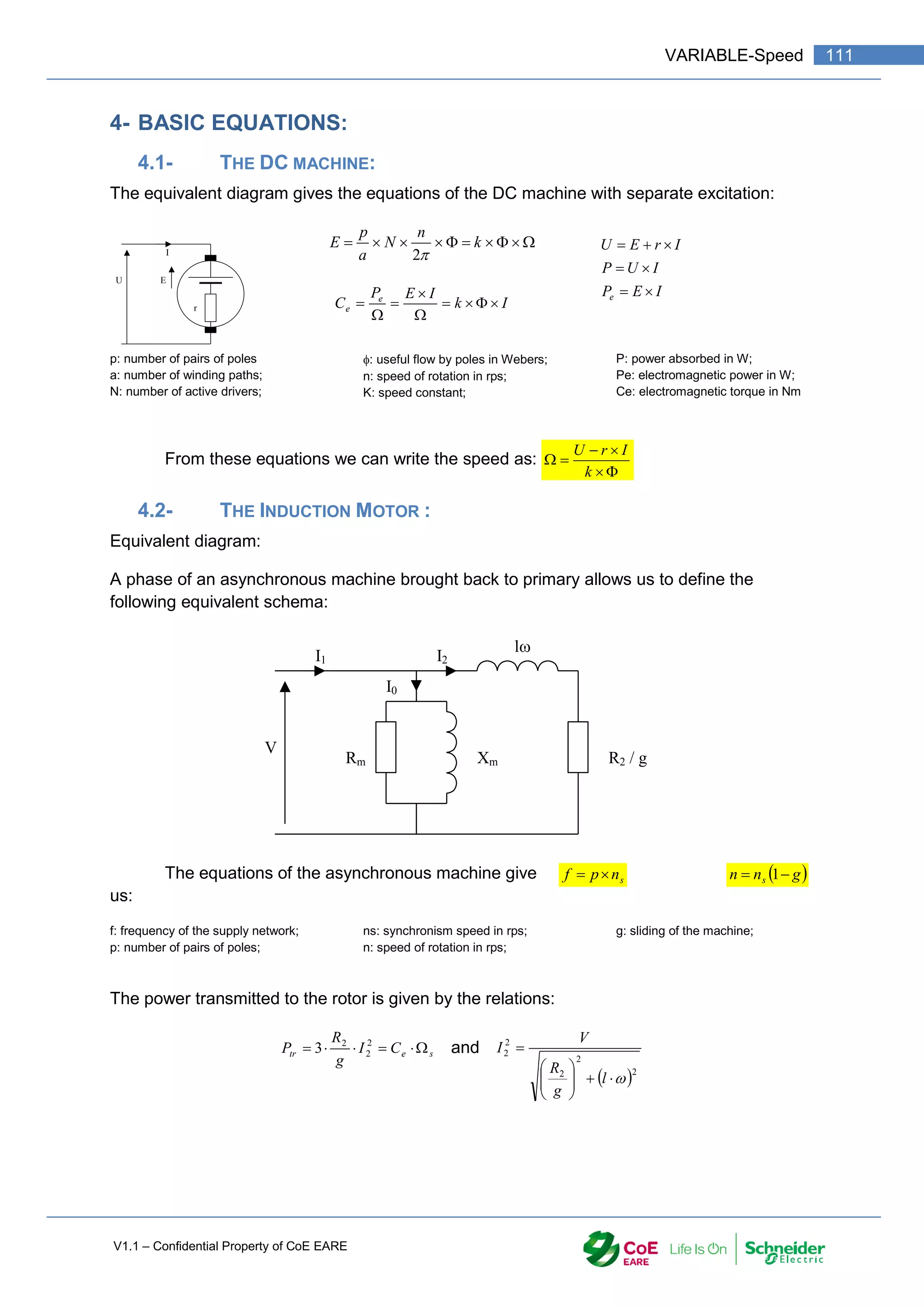
![V1.1 – Confidential Property of CoE EARE
112 [Industrial Automation – Part 1 Installation] [Safety and Security – Basic Industrial wiring]
From there we can write:
The study of this relationship shows that the
maximum torque is
2
2 .
.
.
.
1
.
.
2
R
l
g
l
g
R
C
C eMax
e
and
2
.
.
2
.
3
V
l
p
CeMax
Ce: electromagnetic torque;
p: number of pairs of poles;
R2: rotor resistance;
: pulsation of the network;
l: rotor reactance;
V: supply voltage;
5- THE SPEED VARIATION OF A DC MACHINE:
According to the equations, the speed variation can be obtained in two ways:
5.1- ACTION ON THE SUPPLY VOLTAGE U:
For a constant torque (I is constant) and a constant excitation flux, a variation of the speed is
obtained by a variation of the supply voltage.
'.
.
k
I
r
U
n
5.2- ACTION ON THE FLOW :
For a constant torque and a constant voltage, the speed variation is obtained by a variation
of the excitation flux. This method is used when the nominal speed is obtained by variation of
U. A decrease of the flow increases the speed.
5.3- RÉGULATION :
0
C
/Cn
1
2
3
4
0,2
5
0,5 0,75 N/Ns
1
2
2
2
.
.
.
.
1
.
.
.
3
R
l
g
l
g
R
V
l
p
Ce
](https://image.slidesharecdn.com/iaindustrialautomation-part1-210930233627/75/Ia-industrial-automation-part-1-114-2048.jpg)
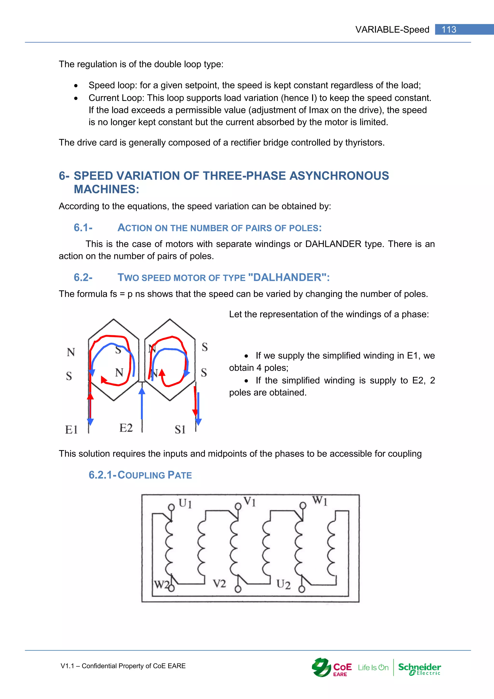
![V1.1 – Confidential Property of CoE EARE
114 [Industrial Automation – Part 1 Installation] [Safety and Security – Basic Industrial wiring]
6.2.2-POSSIBLE CONNECTIONS
Connection Low Speed : Connection High Speed :
6.3- ACTION ON THE SLIP:
Slip variation can only be used if the motor is a wound rotor. By inserting rotor resistors, it is
possible to obtain several operating points. (Modification of R2). (At constant frequency and
voltage)
L1 L2 L3
L2 L1 L3](https://image.slidesharecdn.com/iaindustrialautomation-part1-210930233627/75/Ia-industrial-automation-part-1-116-2048.jpg)
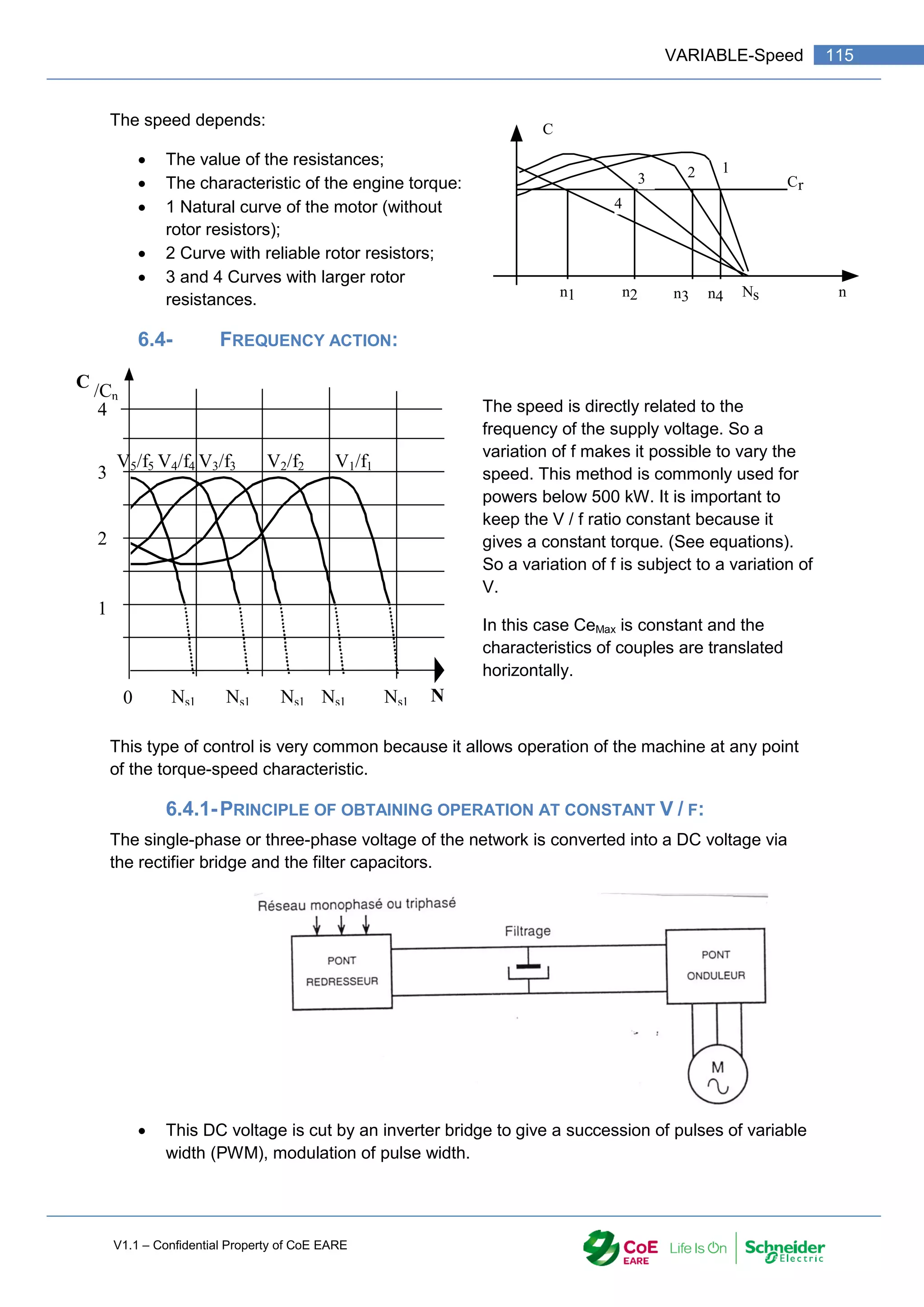
![V1.1 – Confidential Property of CoE EARE
116 [Industrial Automation – Part 1 Installation] [Safety and Security – Basic Industrial wiring]
The adjustment of the width of the pulses and their repetition make it possible to
obtain a variable frequency while maintaining the constant V / F ratio;
The cutting, according to the PWM technique, ensures a smooth and steady rotation
of the machines thanks to a form of output current close to the sinusoid;
The inductance of the motor realizes the smoothing of the current;
6.4.2-OUTPUT CHARACTERISTICS:
Frequency converters provide higher frequencies than the network frequency;
Make sure that the engine supports speeding.
6.4.3-CURRENT AND VOLTAGE CURVES AT THE MOTOR TERMINALS:
The electronic starter is based on a gradual rise in the motor supply voltage during the start-
up phase.
The voltage variation is obtained via a dimmer whose circuit consists of six thyristors
mounted "head-to-tail" by two in each phase of the network.compose de six thyristors montés
“tête bêche” par deux dans chaque phase du réseau.
As a function of the time and the starting time of the thyristors, the dimmer makes it possible
to deliver a variable effective voltage across the motor and at a fixed frequency.
The control of the Dimmer is usually done by a voltage ramp.
The advantages of this type of starter are:
Mechanics:
o Elimination of sudden starts;
o Reduced wear of mechanical transmissions;](https://image.slidesharecdn.com/iaindustrialautomation-part1-210930233627/75/Ia-industrial-automation-part-1-118-2048.jpg)
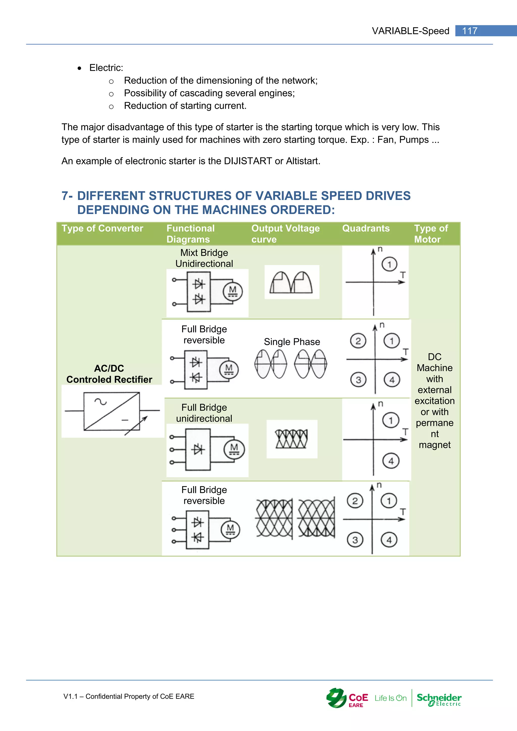
![V1.1 – Confidential Property of CoE EARE
118 [Industrial Automation – Part 1 Installation] [Safety and Security – Basic Industrial wiring]
Type of Converter Functional
Diagrams
Output Voltage
curve
Quadrants Type of
Motor
DC/DC
Chopper
From one to
four quadrants
depending of:
The type of
the bridge
The type of
the control
The type of
the power
supply
DC
Machine
with
serial
excitation
or with
permane
nt
magnet
AC/AC
Dimer
Vrms variable, fixe
frequency
Induction
Motor
with
Squirrel
cage or
winded
rotor
Use as
Starter
AC/AC
Breaking Module * With
breaking
module
Induction
Motor
with
Squirrel
cage](https://image.slidesharecdn.com/iaindustrialautomation-part1-210930233627/75/Ia-industrial-automation-part-1-120-2048.jpg)
![V1.1 – Confidential Property of CoE EARE
120 [Industrial Automation – Part 1 Installation] [Safety and Security – Basic Industrial wiring]
1- INTRODCUTION
A variable-frequency drive (VFD; also termed adjustable-frequency drive, “variable-
voltage/variable-frequency (VVVF) drive”, variable speed drive, AC drive, micro drive or
inverter drive) is a type of adjustable-speed drive used in electro-mechanical drive systems
to control AC motor speed and torque by varying motor input frequency and voltage
VFDs are used in applications ranging from small appliances to large compressors. About
25% of the world's electrical energy is consumed by electric motors in industrial applications,
which can be more efficient when using VFDs in centrifugal load service; however, VFDs'
global market penetration for all applications is relatively small.
Over the last four decades, power electronics technology has reduced VFD cost and size
and has improved performance through advances in semiconductor switching devices, drive
topologies, simulation and control techniques, and control hardware and software.
VFDs are made in a number of different low- and medium-voltage AC-AC and DC-AC
topologies.
2- SYSTEM DESCRIPTION AND OPERATION
A variable-frequency drive is a device used in a drive system consisting of the following three
main sub-systems: AC motor, main drive controller assembly, and drive/operator interface.
2.1- AC MOTOR
The AC electric motor used in a VFD system is usually three-phase induction motor. Some
types of single-phase motors or synchronous motors can be advantageous in some
situations, but generally three-phase induction motors are preferred as the most economical.
Motors that are designed for fixed-speed operation are often used. Elevated-voltage stresses
imposed on induction motors that are supplied by VFDs require that such motors be
designed for definite-purpose.
2.2- CONTROLLER
The VFD controller is a solid-state power electronics conversion system consisting of three
distinct sub-systems: a rectifier bridge converter, a direct current (DC) link, and an inverter.
Voltage-source inverter (VSI) drives are by far the most common type of drives. Most drives
are AC-AC drives in that they convert AC line input to AC inverter output. However, in some](https://image.slidesharecdn.com/iaindustrialautomation-part1-210930233627/75/Ia-industrial-automation-part-1-122-2048.jpg)
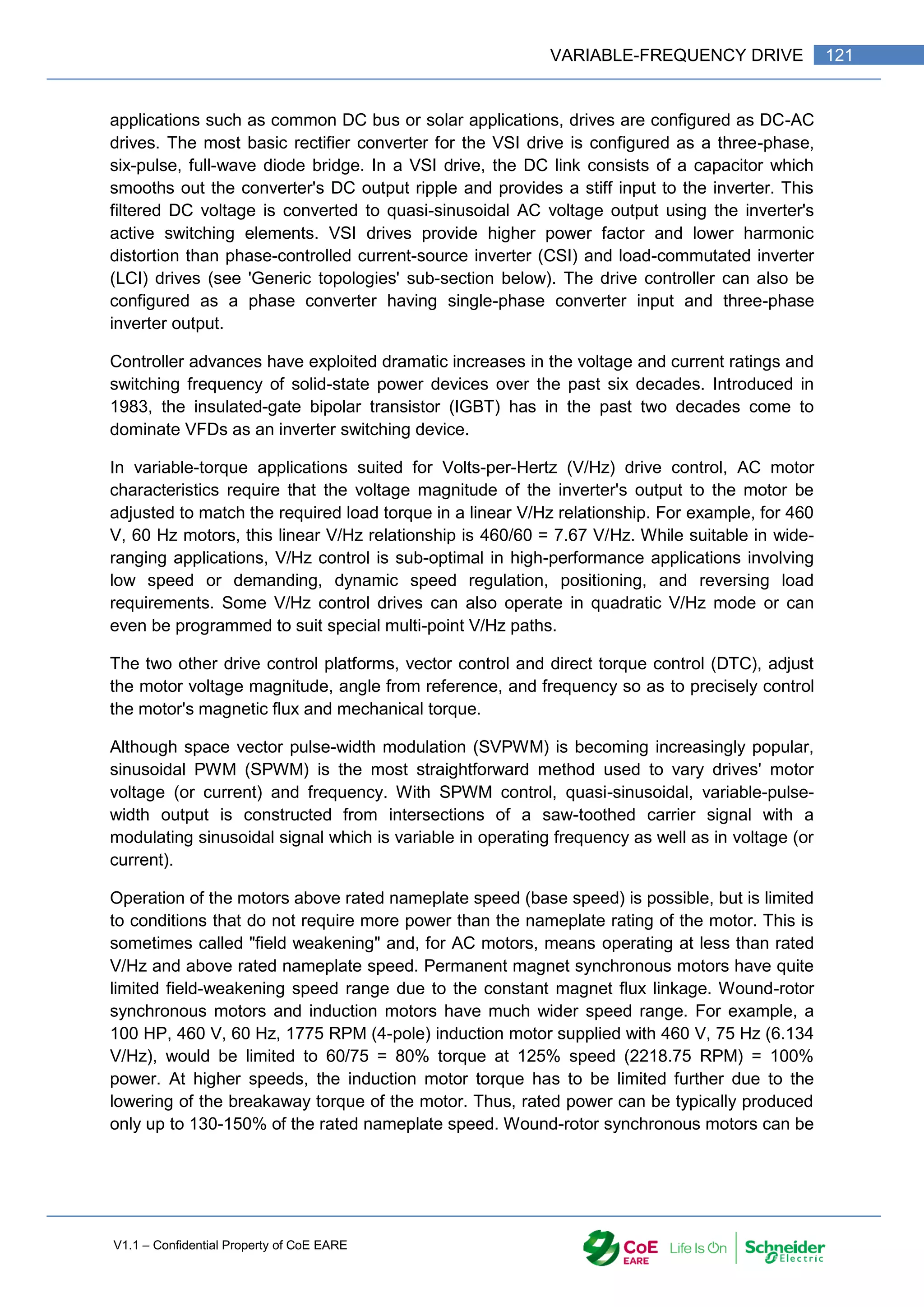
![V1.1 – Confidential Property of CoE EARE
122 [Industrial Automation – Part 1 Installation] [Safety and Security – Basic Industrial wiring]
run at even higher speeds. In rolling mill drives, often 200-300% of the base speed is used.
The mechanical strength of the rotor limits the maximum speed of the motor.
An embedded microprocessor governs the overall operation of the VFD controller. Basic
programming of the microprocessor is provided as user-inaccessible firmware. User
programming of display, variable, and function block parameters is provided to control,
protect, and monitor the VFD, motor, and driven equipment.
The basic drive controller can be configured to selectively include such optional power
components and accessories as follows:
Connected upstream of converter -- circuit breaker or fuses, isolation contactor, EMC
filter, line reactor, passive filter
Connected to DC link -- braking chopper, braking resistor
Connected downstream of inverter—output reactor, sine wave filter, dV/dt filter.
SPWM carrier-sine input & 2-level PWM output
2.3- OPERATOR INTERFACE
The operator interface provides a means for an operator to start and stop the motor and
adjust the operating speed. Additional operator control functions might include reversing, and
switching between manual speed adjustment and automatic control from an external process
control signal. The operator interface often includes an alphanumeric display or indication
lights and meters to provide information about the operation of the drive. An operator
interface keypad and display unit is often provided on the front of the VFD controller as
shown in the photograph above. The keypad display can often be cable-connected and
mounted a short distance from the VFD controller. Most are also provided with input and
output (I/O) terminals for connecting push buttons, switches, and other operator interface
devices or control signals. A serial communications port is also often available to allow the
VFD to be configured, adjusted, monitored, and controlled using a computer.](https://image.slidesharecdn.com/iaindustrialautomation-part1-210930233627/75/Ia-industrial-automation-part-1-124-2048.jpg)
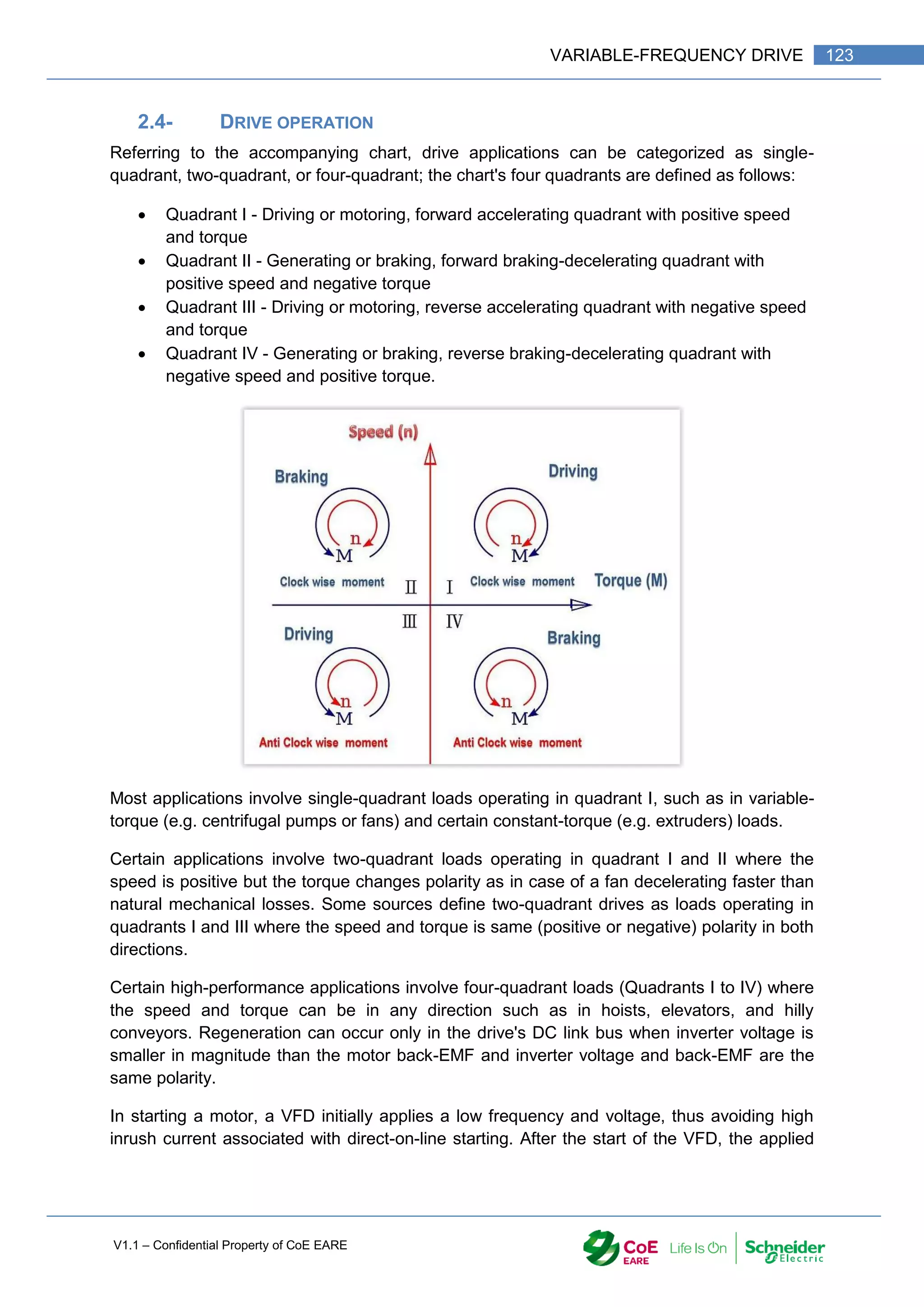
![V1.1 – Confidential Property of CoE EARE
124 [Industrial Automation – Part 1 Installation] [Safety and Security – Basic Industrial wiring]
frequency and voltage are increased at a controlled rate or ramped up to accelerate the load.
This starting method typically allows a motor to develop 150% of its rated torque while the
VFD is drawing less than 50% of its rated current from the mains in the low-speed range. A
VFD can be adjusted to produce a steady 150% starting torque from standstill right up to full
speed. However, motor cooling deteriorates and can result in overheating as speed
decreases such that prolonged low-speed operation with significant torque is not usually
possible without separately motorized fan ventilation.
With a VFD, the stopping sequence is just the opposite as the starting sequence. The
frequency and voltage applied to the motor are ramped down at a controlled rate. When the
frequency approaches zero, the motor is shut off. A small amount of braking torque is
available to help decelerate the load a little faster than it would stop if the motor were simply
switched off and allowed to coast. Additional braking torque can be obtained by adding a
braking circuit (resistor controlled by a transistor) to dissipate the braking energy. With a four-
quadrant rectifier (active front-end), the VFD is able to brake the load by applying a reverse
torque and injecting the energy back to the AC line.
3- BENEFITS
3.1- ENERGY SAVINGS
Many fixed-speed motor load applications that are supplied direct from AC line power can
save energy when they are operated at variable speed by means of VFD. Such energy cost
savings are especially pronounced in variable-torque centrifugal fan and pump applications,
where the load's torque and power vary with the square and cube, respectively, of the speed.
This change gives a large power reduction compared to fixed-speed operation for a relatively
small reduction in speed. For example, at 63% speed a motor load consumes only 25% of its
full-speed power. This reduction is in accordance with affinity laws that define the relationship
between various centrifugal load variables.
In the United States, an estimated 60-65% of electrical energy is used to supply motors, 75%
of which are variable-torque fan, pump, and compressor loads. Eighteen percent of the
energy used in the 40 million motors in the U.S. could be saved by efficient energy
improvement technologies such as VFDs.
Only about 3% of the total installed bases of AC motors are provided with AC drives.
However, it is estimated that drive technology is adopted in as many as 30-40% of all newly
installed motors.
An energy consumption breakdown of the global population of AC motor installations is as
shown in the following table:](https://image.slidesharecdn.com/iaindustrialautomation-part1-210930233627/75/Ia-industrial-automation-part-1-126-2048.jpg)
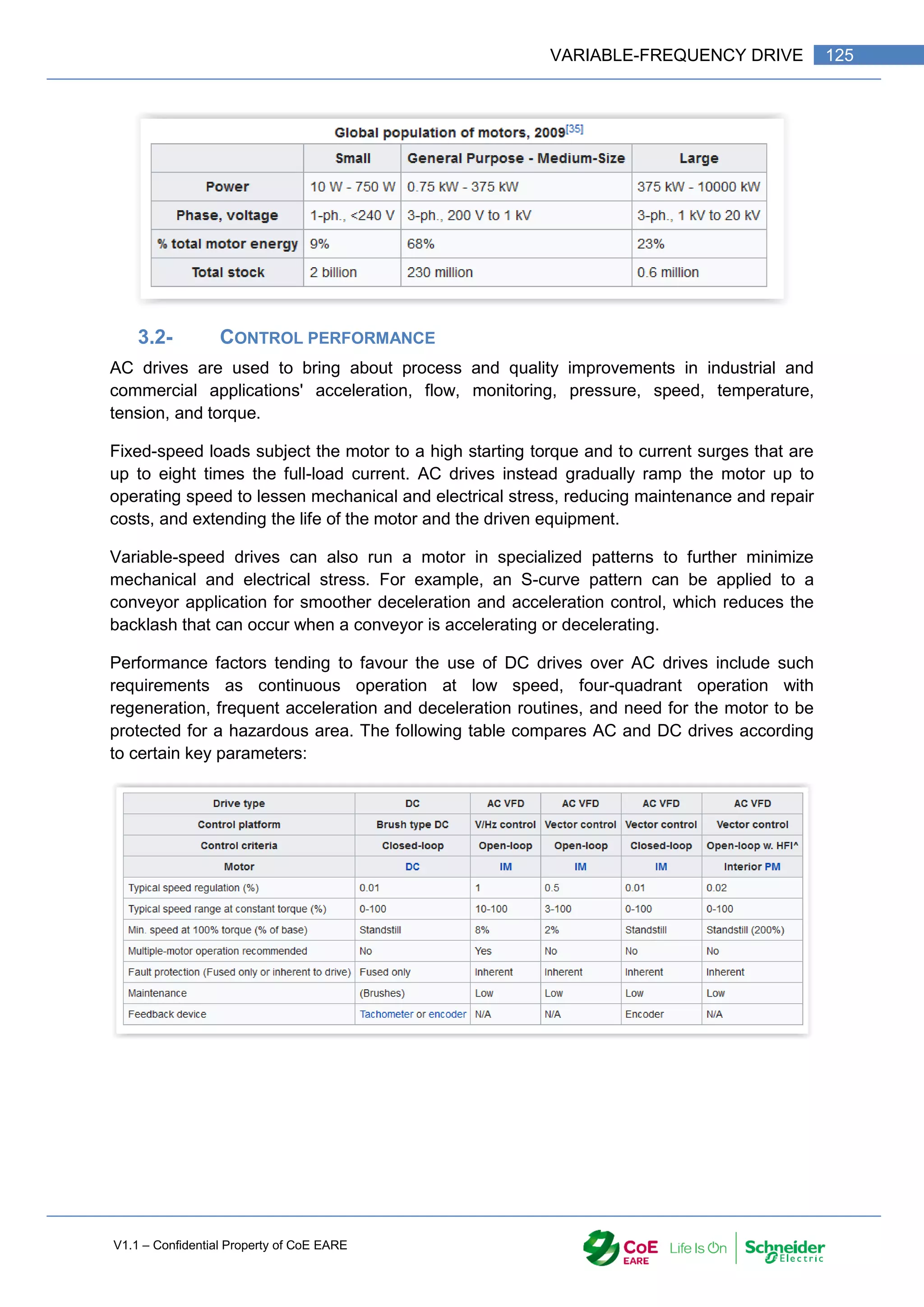
![V1.1 – Confidential Property of CoE EARE
126 [Industrial Automation – Part 1 Installation] [Safety and Security – Basic Industrial wiring]
4- VFD TYPES AND RATINGS
4.1- GENERIC TOPOLOGIES
Topology of VSI drive Topology of CSI drive
Six-step drive waveforms Topology of direct matrix converter
AC drives can be classified according to the following generic topologies:
Voltage-source inverter (VSI) drive topologies (see image): In a VSI drive, the DC
output of the diode-bridge converter stores energy in the capacitor bus to supply stiff
voltage input to the inverter. The vast majority of drives are VSI type with PWM
voltage output.
Current-source inverter (CSI) drive topologies (see image): In a CSI drive, the DC
output of the SCR-bridge converter stores energy in series-Inductor connection to
supply stiff current input to the inverter. CSI drives can be operated with either PWM
or six-step waveform output.
Six-step inverter drive topologies (see image) Now largely obsolete, six-step drives
can be either VSI or CSI type and are also referred to as variable-voltage inverter
drives, pulse-amplitude modulation (PAM) drives, square-wave drives or D.C.
chopper inverter drives. In a six-step drive, the DC output of the SCR-bridge](https://image.slidesharecdn.com/iaindustrialautomation-part1-210930233627/75/Ia-industrial-automation-part-1-128-2048.jpg)
![V1.1 – Confidential Property of CoE EARE
128 [Industrial Automation – Part 1 Installation] [Safety and Security – Basic Industrial wiring]
drives can reach 100 MW, a range of different drive topologies being involved for different
rating, performance, power quality, and reliability requirements.
4.5- DRIVES BY MACHINES AND DETAILED TOPOLOGIES
It is lastly useful to relate VFDs in terms of the following two classifications:
In terms of various AC machines as shown in Table 1 below
In terms of various detailed AC-AC converter topologies shown in Tables 2 and 3
below.
BLDM PM trapezoid machine (Brushless DC electric motor)
CSI Current source inverter
GTO Gate turn-off thyristor
IGBT Insulated gate bipolar transistor
LCI Load commutated inverter
LV Low voltage
MV Medium voltage
PAM Pulse-amplitude modulation
PM Permanent magnet
PMSM Permanent magnet synchronous generator
PWM Pulse-width modulation
SyRM Synchronous reluctance machine
VRM Variable-reluctance machine
VSI Voltage source inverter
VVI Variable-voltage inverter
WFSM Wound-field synchronous machine
WRIM Wound-rotor induction motor](https://image.slidesharecdn.com/iaindustrialautomation-part1-210930233627/75/Ia-industrial-automation-part-1-130-2048.jpg)
![V1.1 – Confidential Property of CoE EARE
130 [Industrial Automation – Part 1 Installation] [Safety and Security – Basic Industrial wiring]
1- OBJECTIVE
Drawing and electrical circuit according to the standards
Implement electrical wiring according to the standards
Select the equipment in order to design an electrical circuit
Establish the list of required equipment in order to make the industrial electrical wiring
2- THE MODULATION OF ENERGY:
The energy modulation allows from a fixed power source, to create a variable power source.
We can thus vary:
• The DC voltage
• the RMS Voltage;
• The DC current;
• The RMS current;
• The power
According to the type of power source, different modulators are distinguished:
AC Sources DC Sources
Fixed Voltage
Fixed Frequency
Fixed voltage
Rectifier
Inverter
Variable Voltage
Fixed Frequency
Variable Voltage
Controlled
Rectifier
Inverter
PWM Type
Dimmer
Chopper
Variable Voltage
Fixed Frequency
Controlled
Inverter
Fig 1 : Energy modulation
In the following part of this course, we will study the AC/AC energy modulation on
RESISTIVE load. The DIMMER and its command.](https://image.slidesharecdn.com/iaindustrialautomation-part1-210930233627/75/Ia-industrial-automation-part-1-132-2048.jpg)
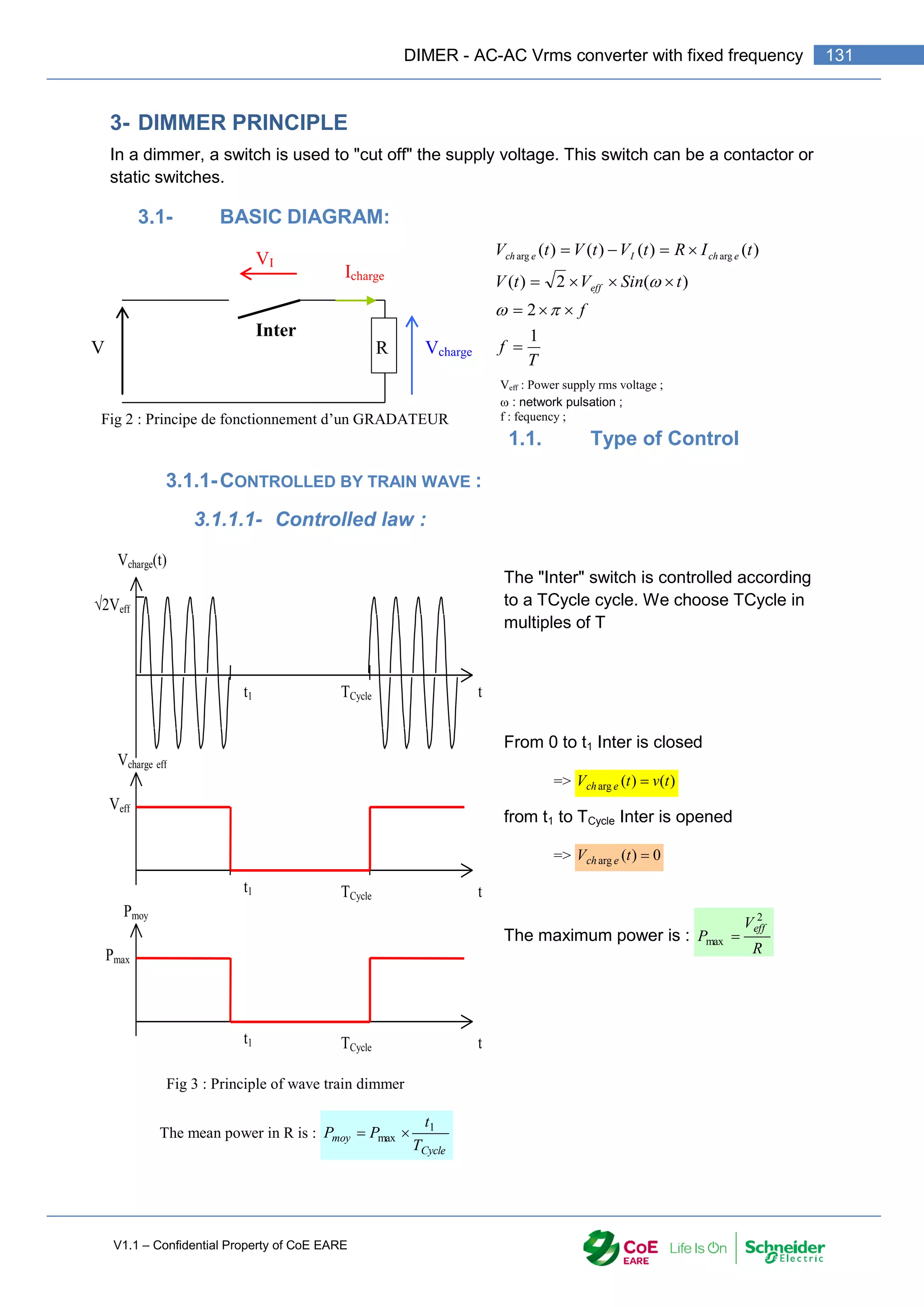
![V1.1 – Confidential Property of CoE EARE
132 [Industrial Automation – Part 1 Installation] [Safety and Security – Basic Industrial wiring]
Pmoy is linear and
function of teh ratio
Cycle
T
t1
1.1.1.1. Use of
wave train dimmer :
This type of control is mainly used in resistance heater control.
3.1.1.2- Design :
The witch can be :
• A contactor if the switching cycle TCycle is > 1 min.
• Thyristors otr Triac if teh switching time TCycle is < 1min. (Static contactor)
3.1.2-CONTROL BY PHASE ANGLE:
3.1.2.1- Controlled law :
The switch is controlled on half period (T/2):
From 0 to à t2 (0 to .t2) Inter is open => 0
)
(
arg
t
V e
ch
From t2 to T/2 (.t2 to ) Inter is closed => )
(
)
(
arg t
v
t
V e
ch
From T/2 to t2+T/2 (to .t2+T/2)) Inter is open => 0
)
(
arg
t
V e
ch
From t2+T/2 to T (.t2+T/2) to 2.) Inter is closed => )
(
)
(
arg t
v
t
V e
ch
In this case , Voltage and Current are not sinusoidal
Cycle
T
t1
1
0
Pmax
Pmoy
Fig 4 : Power in load controlled by wave train dimmer](https://image.slidesharecdn.com/iaindustrialautomation-part1-210930233627/75/Ia-industrial-automation-part-1-134-2048.jpg)
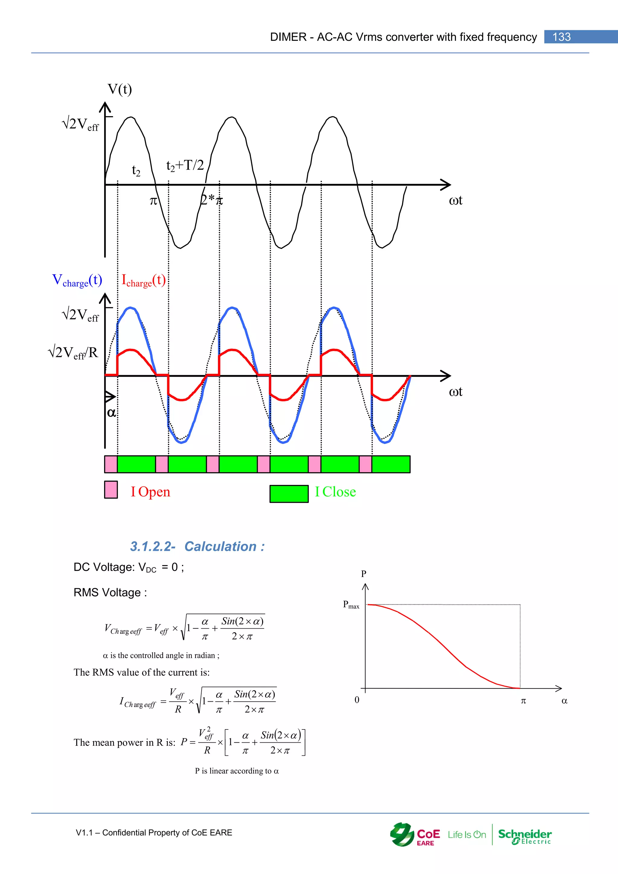
![V1.1 – Confidential Property of CoE EARE
134 [Industrial Automation – Part 1 Installation] [Safety and Security – Basic Industrial wiring]
1.1.2. Use of the dimmer :
This type of Dimmer is used mainly to control lighting.
3.1.3-DESIGN :
The switch is :
• Thyristors or Triac.
• This technology is also used to control the starting of Induction motor (Altisart)
3.2- MIXTE CONTROL :
This type of control is a mixt between
the two previous control types: Train
wave and Phase angle control
The Voltage RMS value will change
according to t1 and . The mean power is
function of the two parameters:
Cycle
eff
moy
T
t
Sin
R
V
P 1
2
2
2
1
This type of Dimmer allows a detailed
control pf the power.
4- TECHNICAL DESIGN :
Dimmer on the market are mostly designed with power electronics components. Dimmer are
built with Thyristor or Triac or power up to few KW in single-phase or three-phase systems.
4.1- SINGLE_PHASE DIMMER :
• Brand : EUROTHERM
• Voltage : 240 V 50 Hz ;
• Control Vdc 0 – 10 V = ;
• Control by phase angle;
• Current rating 16 A.
2Veff
Vcharge(t)
t
TCycle
t1
Fig 7 : Dimmer with mixte control
0
Pmax
P
t1/Tc
Fig 8 Power in load controlled by a mixted dimmer
Ph
N
Ph
N
Commande
Logique de
commande
Réseau Utilisation](https://image.slidesharecdn.com/iaindustrialautomation-part1-210930233627/75/Ia-industrial-automation-part-1-136-2048.jpg)
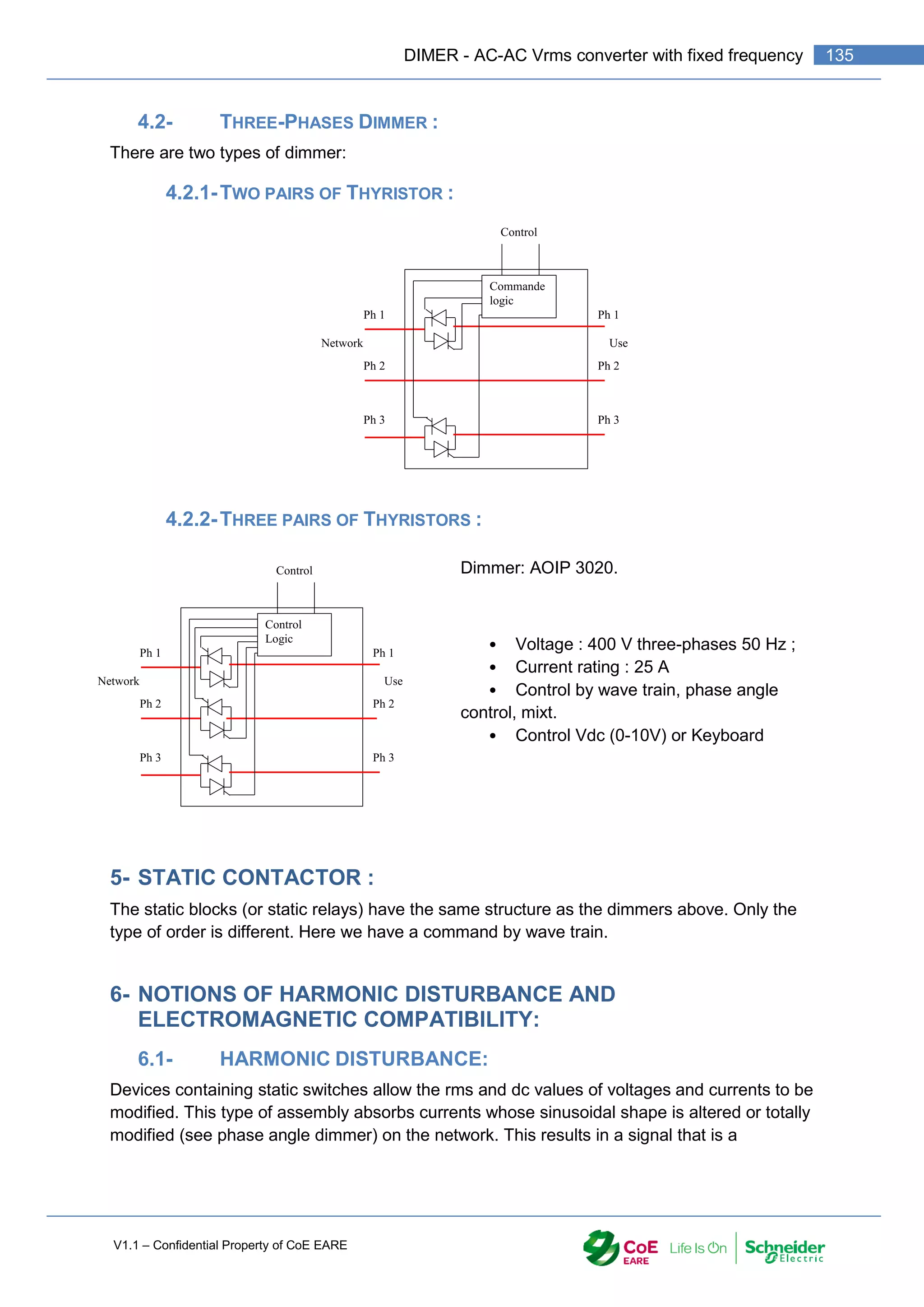
![V1.1 – Confidential Property of CoE EARE
136 [Industrial Automation – Part 1 Installation] [Safety and Security – Basic Industrial wiring]
superposition of sinusoids with multiple frequencies of the frequency of the network (these
are the Harmonics).
This type of current causes disturbances of the network (PLN in particular). To limit the
disturbances, the standards fixed a maximum value of Harmonic Distortion ie a
THDmaximum = 8% for current and voltage in LV.
6.2- EFFECT OF BAD THD :
Le tableau suivant définit les conséquences sur les appareils d'un mauvais THD.
Equipment Effect of the harmonics
Motors
Induction, Synchronous motor, Generator
Additional heating (Joule effect) in the stator windings. Oscillatory couples.
Increase in noise
Transformer
Additional losses in the iron (by Foucault currents) and in the windings (by
Joule effect). Risk of saturation in the presence of even harmonics.
Cable
Increased losses especially in the neutral cable where are added the
harmonics of rank 3 and multiples of 3. Additional dielectric losses.
Power electronics
(Thyristor rectifier bridges, transistors,
etc.).
Functional disorders related to the waveform (switching, synchronization).
Power capacitors Additional dielectric losses leading to premature aging of the capacitors
Computers
Malfunction related to pulsating couples of
magnetic media drive motors
Protective devices
(Fuses, magneto-thermic circuit breakers
...)
Inopportune operation
Energy meter Measurement errors
TV IMAGE distortion
Discharge lamps Risk of wobbling under the effect of the harmonic of rank 2
6.3- ELECTROMAGNETIC COMPATIBILITY (EMC) :
Any electronic switch, switching, emits electromagnetic radiation. It causes dissemination in
the environment of a radio wave. This wave has the effect of disrupting the operation of
surrounding devices. (TP with Radio). European Directive 89/336 / EEC of 3 March 1989 set
the EMC standards before placing a device on the market.
7- TO SUM UP
A dimmer with resistive load :
Type of command Use Advantages Disadventages
Phase angle control
Lighting,
Heating
The power is linear to the
control
Disturbance on the network.
(THD <> 0)
Train d'onde Resistive heating
The power is linear to the
control
No harmonics disturbances
(THD 0)
Power not linear](https://image.slidesharecdn.com/iaindustrialautomation-part1-210930233627/75/Ia-industrial-automation-part-1-138-2048.jpg)

![V1.1 – Confidential Property of CoE EARE
138 [Industrial Automation – Part 1 Installation] [Safety and Security – Basic Industrial wiring]
8.1- RESPONSE DOCUMENTS:
2Veff
t
V(t)
t
VL(t) IL(t)
t
VTH(t) ITH1(t)
Doc. Réponse 1 : = 0
2Veff
t
V(t)
t
VL(t) IL(t)
t
VTH(t) ITH1(t)
Doc. Réponse 2 : = /2
2Veff
t
V(t)
t
VL(t) IL(t)
t
VTH(t) ITH1(t)
Doc. Réponse 3 : = ](https://image.slidesharecdn.com/iaindustrialautomation-part1-210930233627/75/Ia-industrial-automation-part-1-140-2048.jpg)
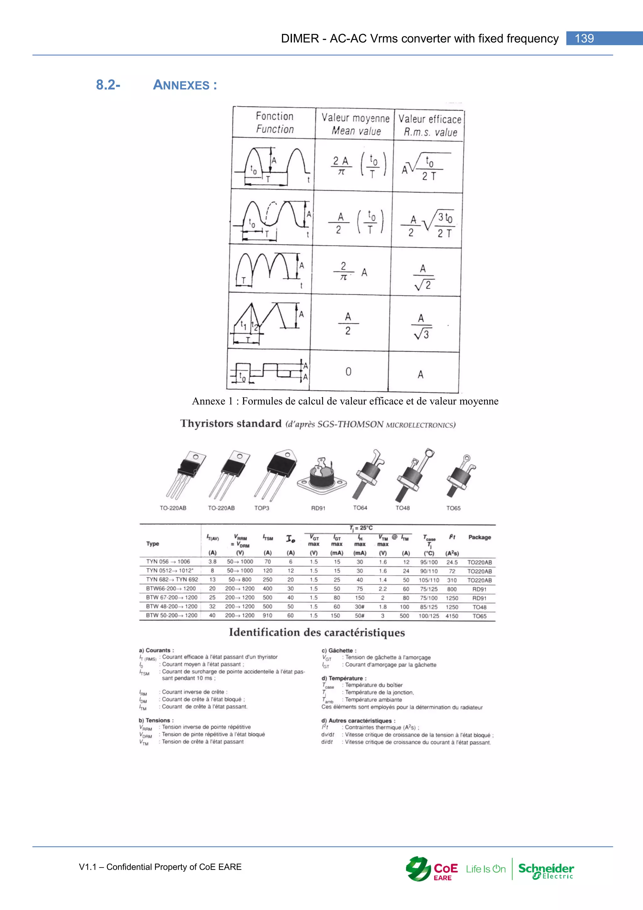
![V1.1 – Confidential Property of CoE EARE
140 [Industrial Automation – Part 1 Installation] [Safety and Security – Basic Industrial wiring]
MANUAL CONTROL](https://image.slidesharecdn.com/iaindustrialautomation-part1-210930233627/75/Ia-industrial-automation-part-1-142-2048.jpg)
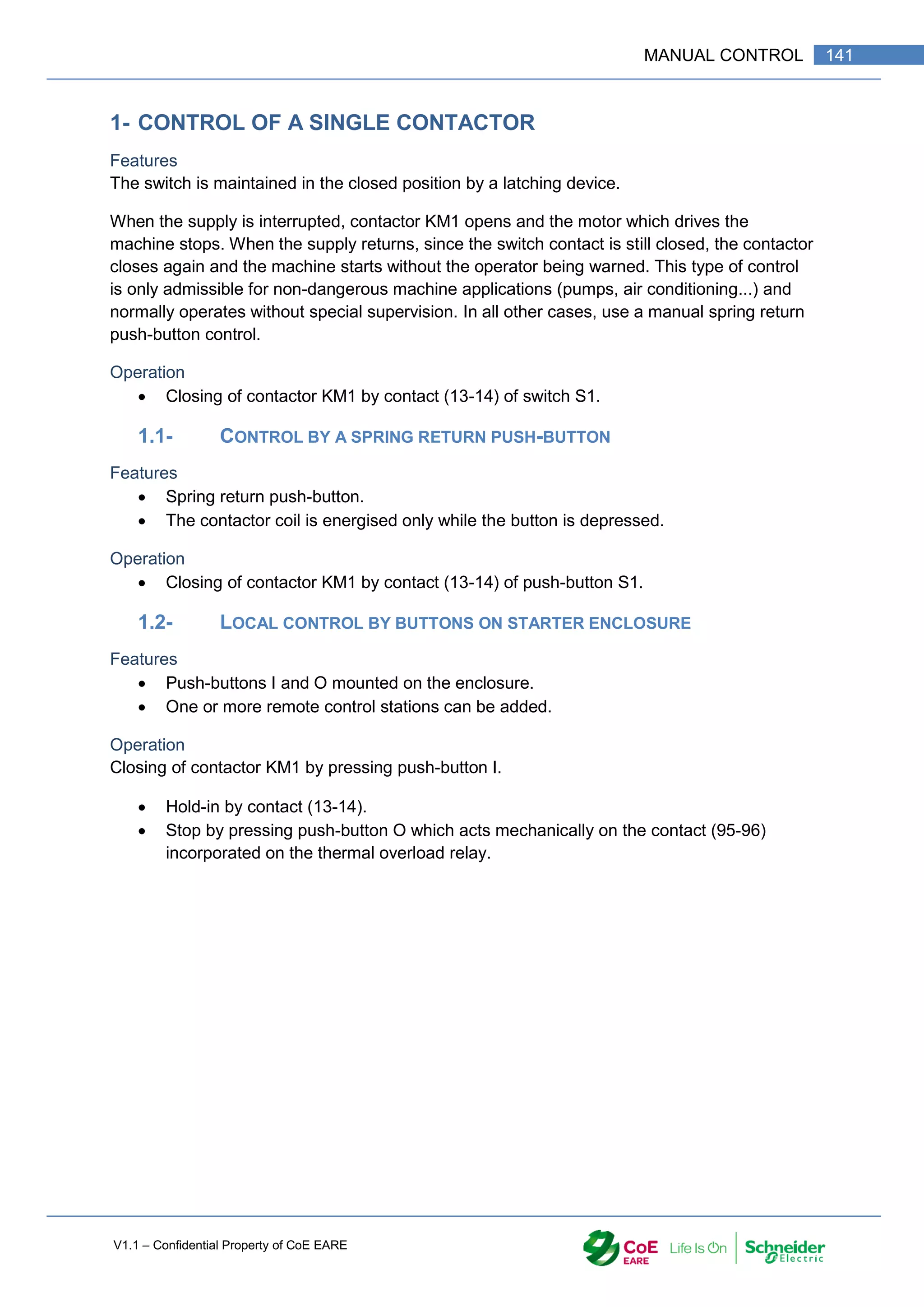
![V1.1 – Confidential Property of CoE EARE
142 [Industrial Automation – Part 1 Installation] [Safety and Security – Basic Industrial wiring]
1.3- REMOTE CONTROL BY 2 SPRING RETURN PUSH-BUTTONS
Features
When the supply is interrupted the contactor opens, S2 must then be pressed in order to
close the contactor again. One or several remote control stations can be incorporated.
Operation
Closing of contactor KM1 by contact (13-14) of push-button S2.
Hold-in by contact (13-14) of KM1.
Stop by contact (21-22) of push-button S1.
1.4- REMOTE CONTROL BY SEVERAL SPRING RETURN PUSH-BUTTONS
Features
Possibility of remote control from several points.
Operation
Closing of contactor KM1 by either of the start buttons S2-S4 connected in parallel.
Hold-in by contact (13-14).
Stop by either of the stop buttons S1-S3 connected in series.
1.5- REMOTE CONTROL, “RUN-INCH”
Features
Possibility of inching for adjustment (conveyor belt), or for the setting up of a machine (lathe,
printing machine), or for the positioning of a workpiece.
Operation
Switch S3 in “run” position :
o Contact (13-14) of switch closed.
o Closing of contactor KM1 by contact (13-14) of the start push-button S2.
o Hold-in by contact (13-14) of KM1.](https://image.slidesharecdn.com/iaindustrialautomation-part1-210930233627/75/Ia-industrial-automation-part-1-144-2048.jpg)
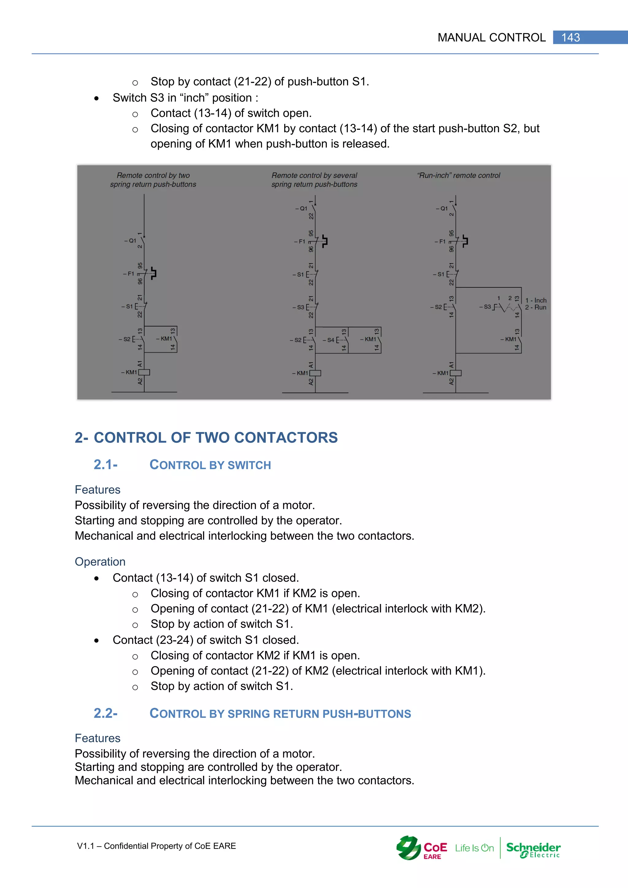
![V1.1 – Confidential Property of CoE EARE
144 [Industrial Automation – Part 1 Installation] [Safety and Security – Basic Industrial wiring]
Operation
Forward :
o Press push-button S2.
o Closing of contactor KM1 if KM2 is open.
o Hold-in of KM1 (13-14).
o Opening of contact (61-62) of KM1 (electrical interlock with KM2).
o Stop by push-button S1.
Reverse :
o Press push-button S3.
o Closing of contactor KM2 if KM1 is open.
o Hold-in of KM2 (13-14).
o Opening of contact (61-62) of KM2 (electrical interlock with KM1).
o Stop by push-button S1.](https://image.slidesharecdn.com/iaindustrialautomation-part1-210930233627/75/Ia-industrial-automation-part-1-146-2048.jpg)

![V1.1 – Confidential Property of CoE EARE
146 [Industrial Automation – Part 1 Installation] [Safety and Security – Basic Industrial wiring]
1- “SUPPLY ON” LAMP
A pilot light indicates that the supply is switched on to the installation, the power being
switched on generally by means of a fused isolator placed on the supply side.
Operation
Isolator Q1 is closed manually.
The pilot light is energised by Q1 (13-14).
2- “ON” LAMP
The pilot light indicates the closing of a contactor.
Operation
Closing of KM1.
Pilot light is energised by KM1 (53-54).
3- “OFF” LAMP
Contrary to the previous example, the opening of the contactor is indicated.
Operation
Pilot light is energised.
Closing of KM1.
Pilot light is extinguished by KM1 (61-62).](https://image.slidesharecdn.com/iaindustrialautomation-part1-210930233627/75/Ia-industrial-automation-part-1-148-2048.jpg)
![V1.1 – Confidential Property of CoE EARE
148 [Industrial Automation – Part 1 Installation] [Safety and Security – Basic Industrial wiring]
1- CONTROL BY SELECTOR SWITCH AND LIMIT SWITCHES
Features
Possibility of reversing the direction of the motor.
Starting and stopping are controlled by the operator.
Automatic stop at the end of travel.
Mechanical and electrical interlocking between the two contactors.
Operation
Contact (13-14) of switch S1 closed.
o Closing of contactor KM1 if contact of limit switch S2 closed and contactor
KM2 open.
o Opening of contact (21-22) of KM1 (electrical interlock with KM2).
o Stop by action of switch S1 or by limit switch S2.
Contact (23-24) of switch S1 closed.
Closing of contactor KM2 if contact of limit switch S3 closed and contactor KM1 open.
Opening of contact (21-22) of KM2 (electrical interlock with KM1).
Stop by action of switch S1 or by limit switch S3.
2- CONTROL BY SPRING RETURN PUSH-BUTTONS AND LIMIT
SWITCHES
Features
Identical to those described opposite.
Operation
Forward: press push-button S2.
o Closing of contactor KM1 if contact of limit switch S4 closed and contactor
KM2 open.
o Hold-in of KM1 (13-14).
o Opening of contact (61-62) of KM1 (electrical interlock with KM2).
o Stop by push-button S1 or by limit switch S4.
Reverse: press push-button S3.
o Closing of contactor KM2 if contact of limit switch S5 closed and contactor
KM1 open.
o Hold-in of KM2 (13-14).
o Opening of contact (61-62) of KM2 (electrical interlock with KM1).
o Stop by push-button S1 or by limit switch S5.](https://image.slidesharecdn.com/iaindustrialautomation-part1-210930233627/75/Ia-industrial-automation-part-1-150-2048.jpg)
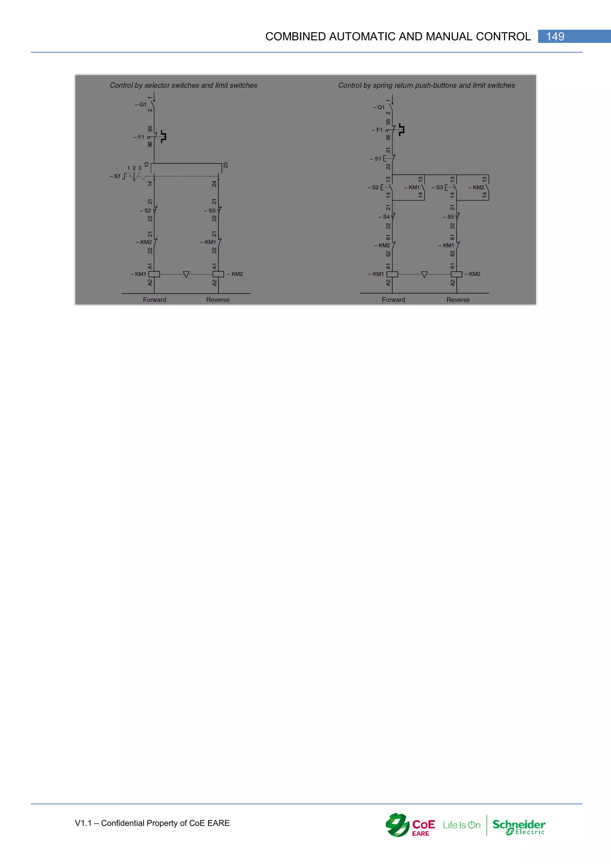
![V1.1 – Confidential Property of CoE EARE
150 [Industrial Automation – Part 1 Installation] [Safety and Security – Basic Industrial wiring]
STARTING OF SQUIRREL CAGE MOTORS](https://image.slidesharecdn.com/iaindustrialautomation-part1-210930233627/75/Ia-industrial-automation-part-1-152-2048.jpg)
![V1.1 – Confidential Property of CoE EARE
152 [Industrial Automation – Part 1 Installation] [Safety and Security – Basic Industrial wiring]
1.3- POWER CIRCUIT OPERATION :
identical to local control.
Control circuit operation
Press I (17-18) or I (13-14). Closing of KM1.
Hold-in of KM1 (13-14). Stop: by pressing O (21-22) or by tripping of thermal overload
relay F1 (95-96).
2- DIRECT-ON-LINE REVERSING STARTER
2.1- LOCAL CONTROL
Power circuit operation
Manual closing of isolator Q1.
Closing of KM1 (forward) or KM2 (reverse).
Features :
Isolator Q1 is rated for the motor FLC (full load current).
Contactors KM1 and KM2 are rated for the motor FLC and utilisation category.
Overload F1 is rated for the motor FLC.
Mechanical and electrical interlocks between KM1 and KM2.
Control circuit operation
Press push-button I or II.
Either KM1 or KM2 closes.
Hold-in of KM1 or KM2 (13-14).
Electrical interlocking of KM1 by KM2 or KM2 by KM1 (61-62).
Manual stop by pressing R.](https://image.slidesharecdn.com/iaindustrialautomation-part1-210930233627/75/Ia-industrial-automation-part-1-154-2048.jpg)
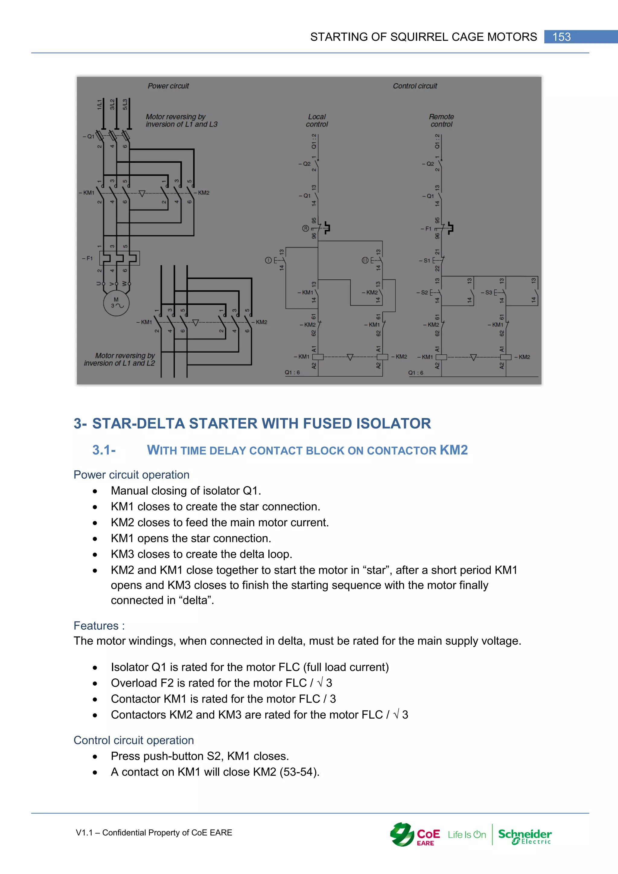
![V1.1 – Confidential Property of CoE EARE
154 [Industrial Automation – Part 1 Installation] [Safety and Security – Basic Industrial wiring]
A contact on KM2 will hold-in KM1 and KM2 (13-14).
After a short delay KM1 will open and KM3 will close (controlled by timed contact 67-
68 on KM2 and contact 21-22 on KM1).
The drive may be stopped by pressing push-button S1.
Features :
Electrical interlocking between KM1 and KM3.
The LA2-D time-delay contact block incorporates a 40 ms time delay between the
opening of its N/C contact and the closing of its N/O contact. This eliminates any risk
of a short-circuit during the star-delta transition, which could be caused by the arcing
of the contactors.](https://image.slidesharecdn.com/iaindustrialautomation-part1-210930233627/75/Ia-industrial-automation-part-1-156-2048.jpg)
![V1.1 – Confidential Property of CoE EARE
156 [Industrial Automation – Part 1 Installation] [Safety and Security – Basic Industrial wiring]
DOL TWO DIRECTION CONTROLLED BY INTEGRATED SYSTEM
TOT - Training of Trainer Code: TOT-M03-PA-006-
TR_004_Ver-00
Title:
DOL two direction controlled by integrated
system
# 004
Module: M4-Industrial Installation Doc: TR - Trainee
Topic: 006 - Industrial wiring
Type of Activity: PA -
Practical Activity
Equipment
:
C03 - Industrial devices for wiring.
Main
Objective
cpt.3-1 - Drawing and electrical circuit according to the standards
cpt.3-3 - Implement electrical wiring according to the standards
cpt.3-4 - Select the equipment in order to design an electrical circuit
cpt.3-5 - Establish the list of required equipment in order to make the electrical wiring of
a building
cpt.3-7 - Perform the commissioning of electrical circuit
Objectives The trainee will be able to :
Duration: 4:0
resources: Docs
- A4 - TeSys U_P_EN.pdf
- A4 - TeSys U_P_EN-Wiring.pdf
- TeSys U_1629984_01A55.pdf
- TeSys U_1639084_01A55.pdf
- TeSys U_163884301A05-10.pdf
Standards :
-](https://image.slidesharecdn.com/iaindustrialautomation-part1-210930233627/75/Ia-industrial-automation-part-1-158-2048.jpg)
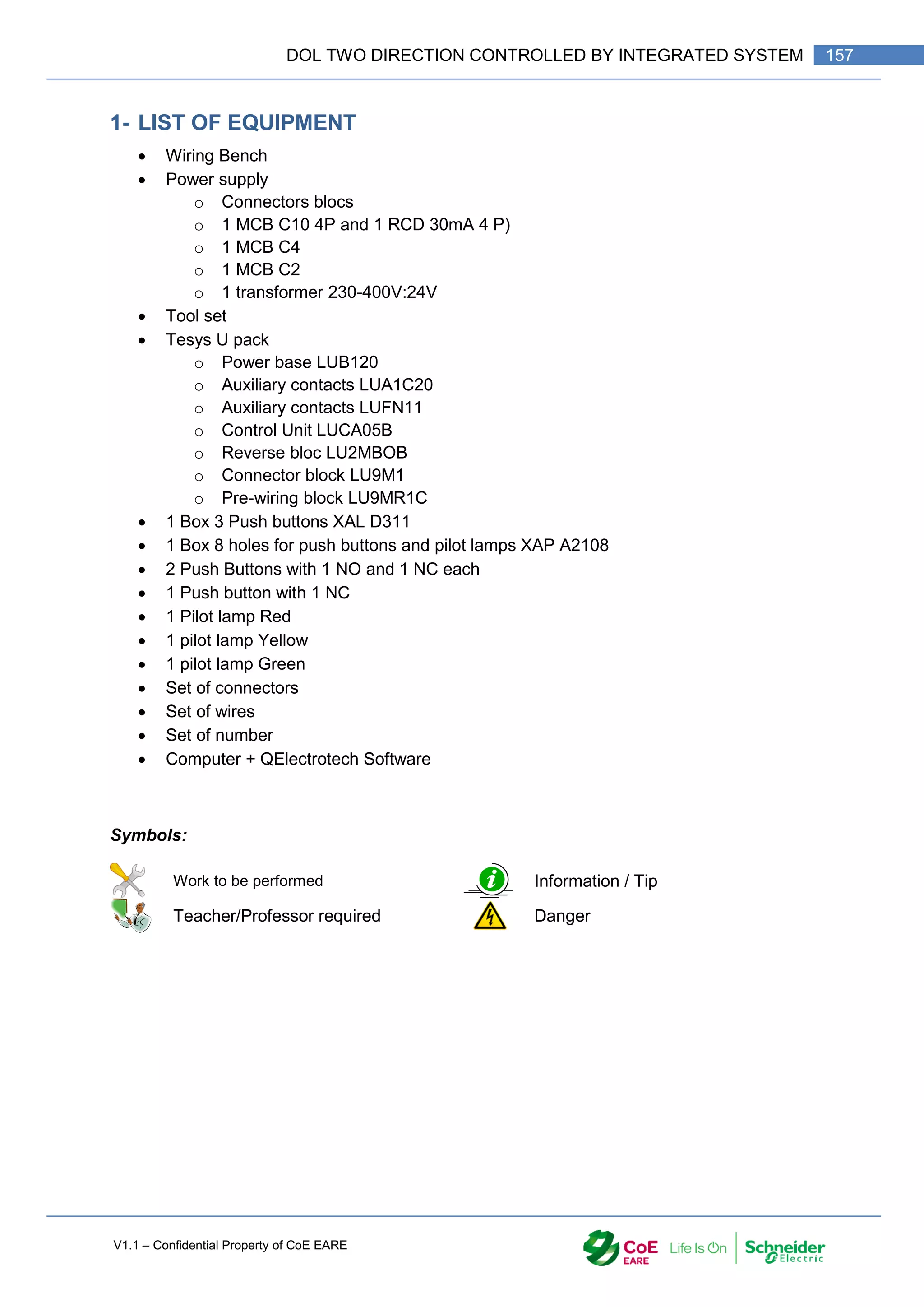
![V1.1 – Confidential Property of CoE EARE
158 [Industrial Automation – Part 1 Installation] [Safety and Security – Basic Industrial wiring]
2- PREAMBLE
The Direct on line starter is to control an induction motor. The control circuit is usually
composes with Switch Disconnector, Fuses or Magnetic Relay, Contactors and overload
relay. All of these devices have the target to control the power supply of the motor and to
protect the equipment against overload and short circuits. For a 2 direction control, additional
equipment is required.
3- TASK 1
With the help of the software QElectrotech, design, according to the standard, a DOL 2
direction circuit to control an Induction Motor.
The devices used must be
Q1: Switch disconnector with Magnetic relay
KM1: Contactor (Forward)
KM2: Contactor (Reverse)
F1: Overload Relay
S0: Emergency Stop Button
S1: Stop Push Button
S2: Forward Push Button
S3: Reverse Push Button
Q 1. What is the function of each device?
Q 2. How many wires do you need to do the wiring?
4- TASK 2
Manufacturers of industrial devices have created new integrated equipment to control
motors. Schneider Electric created the Tesys U system to do that.
By studying the recourse document “A4 - TeSys U_P_EN.pdf” pages A4/2 to A4/9, answer
the following questions:
Q 3. What are the functions included in the Tesys U system?
Q 4. With the equipment at your disposal, indicate the name, reference and function of
each part.
With the help of the resource document “A4 - TeSys U_P_EN-Wiring.pdf”, draw on
QElectrotech the DOL 2 direction circuit.
Q 5. How many wires do you need to do the wiring?
Q 6. Is this integrated system will add advantages on the wiring to compare with the
traditional wiring?](https://image.slidesharecdn.com/iaindustrialautomation-part1-210930233627/75/Ia-industrial-automation-part-1-160-2048.jpg)
![V1.1 – Confidential Property of CoE EARE
160 [Industrial Automation – Part 1 Installation] [Safety and Security – Basic Industrial wiring]
SOFT STARTER
TOT - Training of Trainer Code: TOT-M03-PA-006-
TR_005_Ver-00
Title: Soft Starter # 005
Module: M4-Industrial Installation Doc: TR - Trainee
Topic: 006 - Industrial wiring
Type of Activity: PA -
Practical Activity
Equipment
:
C03 - Industrial devices for wiring.
Main
Objective
cpt.3-1 - Drawing and electrical circuit according to the standards
cpt.3-3 - Implement electrical wiring according to the standards
cpt.3-4 - Select the equipment in order to design an electrical circuit
cpt.3-5 - Establish the list of required equipment in order to make the electrical wiring of
a building
cpt.3-7 - Perform the commissioning of electrical circuit
Objectives The trainee will be able to :
Duration: 1:0
resources: Docs
-
Standards :
-](https://image.slidesharecdn.com/iaindustrialautomation-part1-210930233627/75/Ia-industrial-automation-part-1-162-2048.jpg)
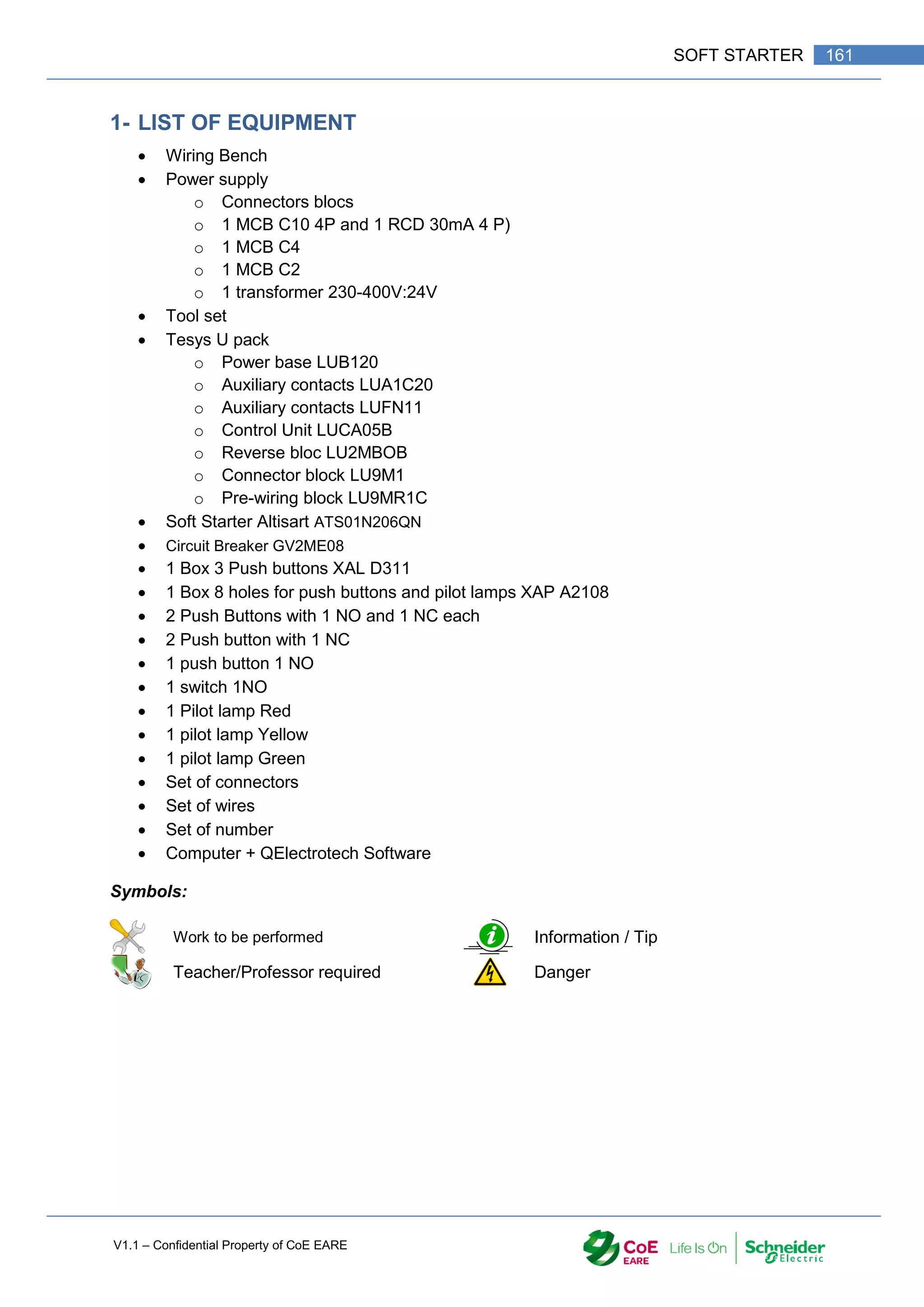
![V1.1 – Confidential Property of CoE EARE
162 [Industrial Automation – Part 1 Installation] [Safety and Security – Basic Industrial wiring]
2- PREAMBLE
The Direct on line starter for Induction Motor produces a huge demand of current. Usually the
starting current is 7 to 10 times the rating current of the motor. This situation can be an issue
for motor with large Power. To solve this issue, starters have been designed such as Star-
Delta, Rotor or Stator starters. The aim is to reduce the starting current.
The new power electronic components have allowed the design of “Electronic Starter”. The
Altistart is one of them. This device will help to control the starting current of the Induction
Motor.
It is composed of dimer that will control the voltage across the motor coil and consequently
the current. But this as a drawback! The toque will be affected and the starting torque will be
less than the DOL one. To fix it, an initial voltage and a bust voltage can be controlled by the
Altisart.
3- TASK 1
By using the technical documents about the Altistart (DIA2ED2140603EN %28web%29.pdf
and ATS01_IS_ATS01N2_1624686_04.pdf) available on the Moodle platform, answer the
following questions:
Q 1. What are the functions of the 3 selector on the altistart?
Q 2. How can we control the start and Stop of the motor?
Q 3. What is the rating of the Altistart in your possession?
4- TAKS 2
With the help of the documents above:
Q 4. Add on your previous wiring diagram the soft starter Altistart. The control of the
starting will be done directly by connecting the terminal “LI2” with the terminal “LI+” of
the Altistart. (You must use the previous wiring (DOL FR/RV with TeSys U system)
Q 5. After validation of the Master Trainer, apply the modifications to your wiring.
Q 6. Perform the commissioning and test your system.
Q 7. Are the start and Stop according to the time diagram given on the data instruction
sheet? (ATS01_IS_ATS01N2_1624686_04.pdf)
Q 8. By using an Oscilloscope and a voltmeter, Observe the voltage on the motor coil.
Describe the evolution of the voltage and the consequences on the motor functioning.
5- TASK 3
Q 9. Modify your installation to control the start and stop of you motor by using a switch.
Q 10. Perform the commissioning and test your system.
Q 11. Are the start and Stop according to the time diagram given on the data instruction
sheet? (ATS01_IS_ATS01N2_1624686_04.pdf)](https://image.slidesharecdn.com/iaindustrialautomation-part1-210930233627/75/Ia-industrial-automation-part-1-164-2048.jpg)

![V1.1 – Confidential Property of CoE EARE
164 [Industrial Automation – Part 1 Installation] [Safety and Security – Basic Industrial wiring]
INDUCTION MOTOR CONTROLLED BY VSD
TOT - Training of Trainer Code: TOT-M03-PA-006-
TR_0006_Ver-00
Title: Induction Motor controlled by VSD # 0006
Module: M4-Industrial Installation Doc: TR - Trainee
Topic: 006 - Industrial wiring
Type of Activity: PA -
Practical Activity
Equipment
:
C03 - Industrial devices for wiring.
Main
Objective
cpt.3-1 - Drawing and electrical circuit according to the standards
cpt.3-4 - Select the equipment in order to design an electrical circuit
cpt.3-7 - Perform the commissioning of electrical circuit
cpt.3-8 - Perform electrical measurement according to the safety and security rules
Objectives The trainee will be able to :
Cliquez ici pour taper du texte.
Duration: 5:0
resources: Docs
-
Standards :
-](https://image.slidesharecdn.com/iaindustrialautomation-part1-210930233627/75/Ia-industrial-automation-part-1-166-2048.jpg)
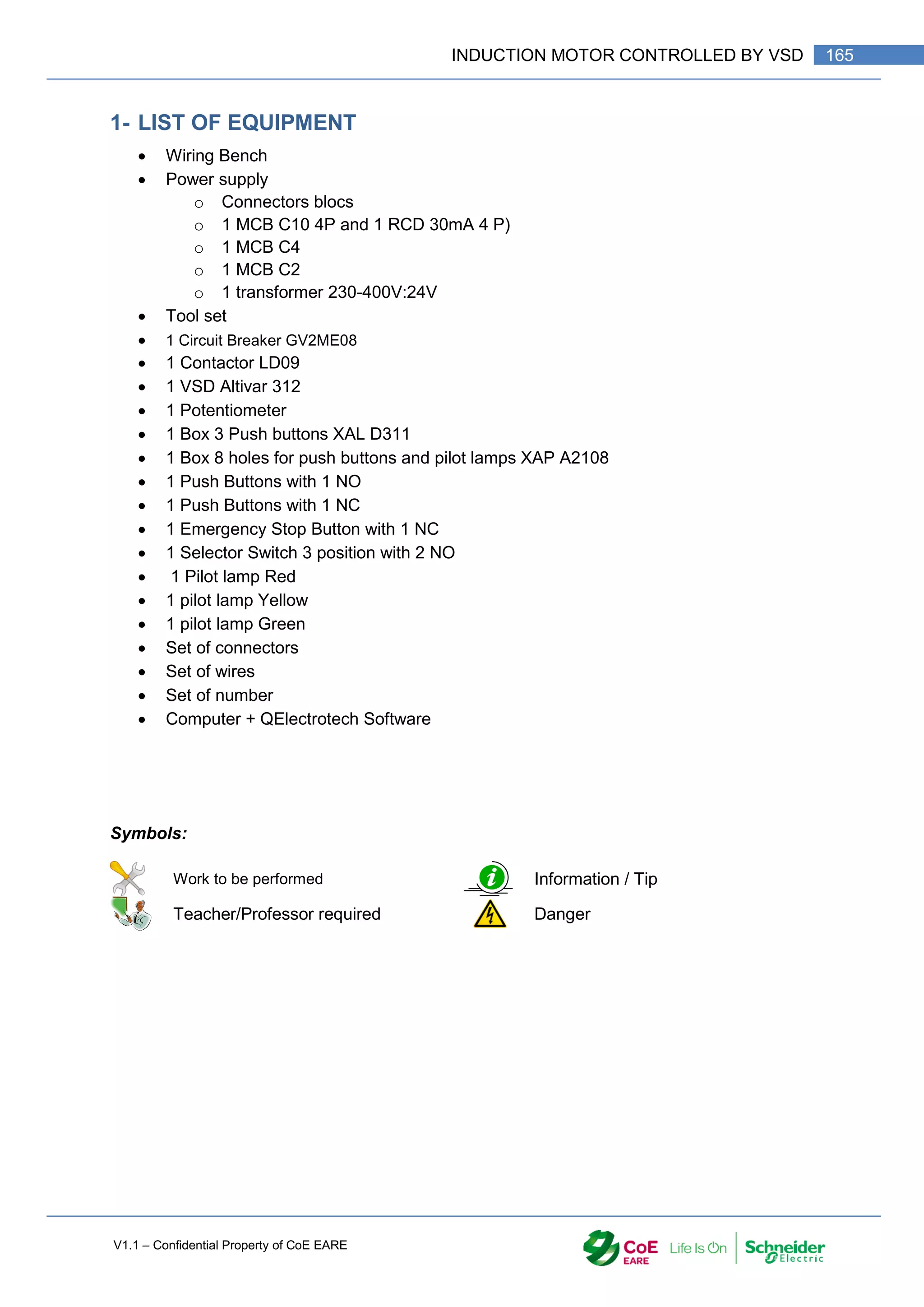
![V1.1 – Confidential Property of CoE EARE
166 [Industrial Automation – Part 1 Installation] [Safety and Security – Basic Industrial wiring]
2- PREAMBLE
To control the starting current of an Induction motor, we can us a soft starter, but if we want
to control more efficiently the starting and the running of the motor, we can use a “Variable
Speed Drive” or VSD.
You will perform in this activity the wiring and the configuration of a VSD to control the speed
of an induction motor.
3- STUDY OF VSD
With the help of the documents
“ATV312_Getting_Started_EN_S1A10942_04.pdf” page 2
“ATV12_user_manual_EN.pdf”, pages 17 to 27
Q 1. Identify the name of the terminals used for the power supply and to connect the
motor.
Q 2. Identify the inputs used to control the motor. (in 2 wires configuration)
a. What input control the Forward, the Reverse direction?
b. Those inputs will be controlled by Switch or Push button?
Q 3. Witch inputs control the speed reference?
a. With what component, the speed reference is setting up?
Q 4. What is the function of the terminal R1A, R1B, R1C?
Q 5. The supply of the VSD will be done with a “Watch Dog” circuit. A Watch Dog circuit
is a circuit that monitor the security of a system. The most common is a DOL style
circuit. It contains at least 1 Emergency Stop Button, a Start push button (Power Up),
a Stop push Button (Power down) and a contactor. The contact “VSD ready is placed
in series with the contactor’s memory contact. With the help of the previous
questions, design the electrical circuit to control an Induction Motor through a VSD
with the following components:
Q1: Main Circuit Breaker
KM1: Watch Dog Contactor
S0: Emergency Stop Button
S1: Power down push button
S2: Power up push button
VSD: Variable Speed Driver ATV312
S10: Turn Switch 3 positions (2 NO contacts) for Forward/Reverse control
P1: 10 K potentiometer to control the speed reference.
Connectors & terminals.
Q 6. After validation from the Master Trainer, collect the equipment and perform the
wiring.
Q 7. Perform the commissioning of your wiring.](https://image.slidesharecdn.com/iaindustrialautomation-part1-210930233627/75/Ia-industrial-automation-part-1-168-2048.jpg)


![V1.1 – Confidential Property of CoE EARE
172 [Industrial Automation – Part 1 Installation] [Safety and Security – Basic Industrial wiring]
TCSESU053FN0.pdf
TCSESU053FN0_User Guide.pdf
Harmony© XB7
Harmony XB7_XB7EV03MP.pdf
Harmony XB7_XB7EV04MP.pdf
Harmony XB7_XB7EV05MP.pdf
Harmony XB7_XB7NA31.pdf
Harmony XB7_XB7NA42.pdf
Harmony XB7_XB7ND21.pdf
Harmony© XB7_Catalog 2019.pdf
Instruction_Sheet_Harmony_XB7-1.pdf
Instruction_Sheet_Harmony_XB7.pdf
HMI - HMIGXU3512
Brochure - HMIGXU (2015).pdf
Catalogue - HMIGXU (2015).pdf
Easy Harmony GXU_HMIGXU3512.pdf
EAV83639_02.pdf
HMI_Catalog 2019.pdf
M221-Module MT3TI4-TM3AQ4-Analog Inputs-Outputs
Modicon TM3_TM3AQ4.pdf
Modicon TM3_TM3TI4.pdf
Modicon_TM3--_TM3T--_Installation guide.pdf
Modicon_TM3_Expansion Modules Configuration.pdf
Modicon_TM3_I-O expansion modules for Modicon-2019.pdf
M221-PLC
M221 Advanced Functions.pdf
M221 Brochure.pdf
M221 Catalog 2015.pdf
M221 CPU Hardware Guide.pdf
M221 Generic Function.pdf
M221 Logic Controler-Hardware Guide.pdf
M221 Modbus Master Example.pdf
M221 Operator Display.pdf
2M221 Programming Guide.pdf
M221 SMS Example.pdf
M221-TM221CE40R
M221_Catalog_2019.pdf
PLC - Modicon M221_TM221CE40R.pdf
M221 _Programing Guide.pdf
MCB - A9F04206
DIN Rail modular devices_A9F74206.pdf
Instruction Sheet iC60N.pdf
3.IA-Sensor Kit
ABL1- Power Supply
Phaseo ABL1_ABL1REM24042.pdf
Phaseo ABLA1_User Guide.pdf
Harmony© XB7
Harmony XB7_XB7EV06BP.pdf
Harmony© XB7_Catalogue.pdf
sensors
163439701A55.pdf
BBV13273.pdf
Opto-electronic rotary encoders_instruction sheet.pdf
OsiSense XCC_XCC1406PR01K.pdf
OsiSense XC_XCMD2110L1.pdf](https://image.slidesharecdn.com/iaindustrialautomation-part1-210930233627/75/Ia-industrial-automation-part-1-174-2048.jpg)