The document presents a comparative study of hysteresis-based voltage and current control techniques for grid-connected solar photovoltaic systems, highlighting the need for improved inverter control to maintain power quality amid increased grid harmonics. Two methods, hysteresis voltage control (HVC) and hysteresis current control (HCC), are examined through MATLAB/Simulink simulation, demonstrating that HVC outperform HCC in terms of total harmonic distortion (THD) within the standards set by IEEE and IEC. The findings emphasize the importance of optimizing inverter design to address challenges associated with integrating solar PV systems into existing power grids.
![International Journal of Electrical and Computer Engineering (IJECE)
Vol. 8, No. 5, October 2018, pp. 2671~2681
ISSN: 2088-8708, DOI: 10.11591/ijece.v8i5.pp2671-2681 2671
Journal homepage: http://iaescore.com/journals/index.php/IJECE
Hysteresis-based Voltage and Current Control Techniques for
Grid Connected Solar Photovoltaic Systems: Comparative
Study
S. Raja Mohamed1
, P. Aruna Jeyanthy2
, D. Devaraj3
1
Department of Electrical and Computer Engineering, King Faisal University, Saudi Arabia
2,3
Department of Electrical Engineering, Kalashalingham University, India
Article Info ABSTRACT
Article history:
Received Oct 3, 2017
Revised Dec 31, 2017
Accepted Aug 20, 2018
Solar PV system development and integration with existing grid is very fast
in recent years all over the world, as they require limited maintenance,
pollution free and simple structure. When observing the factors affecting the
performance of the grid connected solar photovoltaic system, the inverter
output voltage with harmonics add with the harmonics generated due to the
non-linear loads, retain a bigger challenge to maintain power quality in the
grid. To maintain grid power quality, better inverter control technique should
be developed. This paper presents the two control techniques for grid-tied
inverters. This study developed the hysteresis controller for the inverter.
Hysteresis controller used in this work two way (i) Voltage control mode (ii)
Current control mode. Matlab/Simulink model is developed for the proposed
system. Further the study presents the comparative evaluation of the
performance of both control techniques based on the percentage of total
harmonic distortion (THD) with the limits specified by the standards such as
IEEE 1547 and IEC 61727 and IEEE Std 519-2014.
Keyword:
Hysteresis controller
Power quality
Solar photovoltaic system
Total harmonic distortion
Voltage source inverter
Copyright © 2018 Institute of Advanced Engineering and Science.
All rights reserved.
Corresponding Author:
S. Raja Mohamed,
Department of Electrical and Computer Engineering,
King Faisal University,
PO Box: 380; PC-31982-Hofuf, Al-Hasa, Saudi Arabia.
Email: rsumsudeen@kfu.edu.sa
1. INTRODUCTION
Due to the limited fossil fuel reserve availability, global warming and increasing the fuel cost, all the
countries turn towards to use of green energy sources, such as wind energy bio-energy and photovoltaic
energy, fuel cell etc. Among the various types of Distributed generation (DG) systems, solar PV system
development is very fast in recent years, as they require limited maintenance, pollution free and simple
structure. While Solar PV has many advantages at the same time, it also poses several challenges, like when
increase the penetration of solar PV system into the existing grid, many problems created for example
instability, increase harmonics level, voltage variation and flicker etc. Harmonics is found to be most
important problem out all the above issues related to the quality power inject into the grid. Considering the
above reasons there is an essential to develop novel inverter topology and controller to improve the quality of
solar energy produced [1]. In [2] authors have presented the comparison of sinusoidal PWM voltage and
hysteresis current control methods of grid-tied inverters act as a reactive power compensator.
The results conclude that, when switching frequency of the inverter is low, remove the unwanted
ripples of the output current is more difficult task. For this reasons voltage control technique is preferred. In
[3] presents a current control loop mechanism in 3-phase inverter which is used to control the reactive and
active power as well as maintain the good power quality. But, the study found that proposed current control
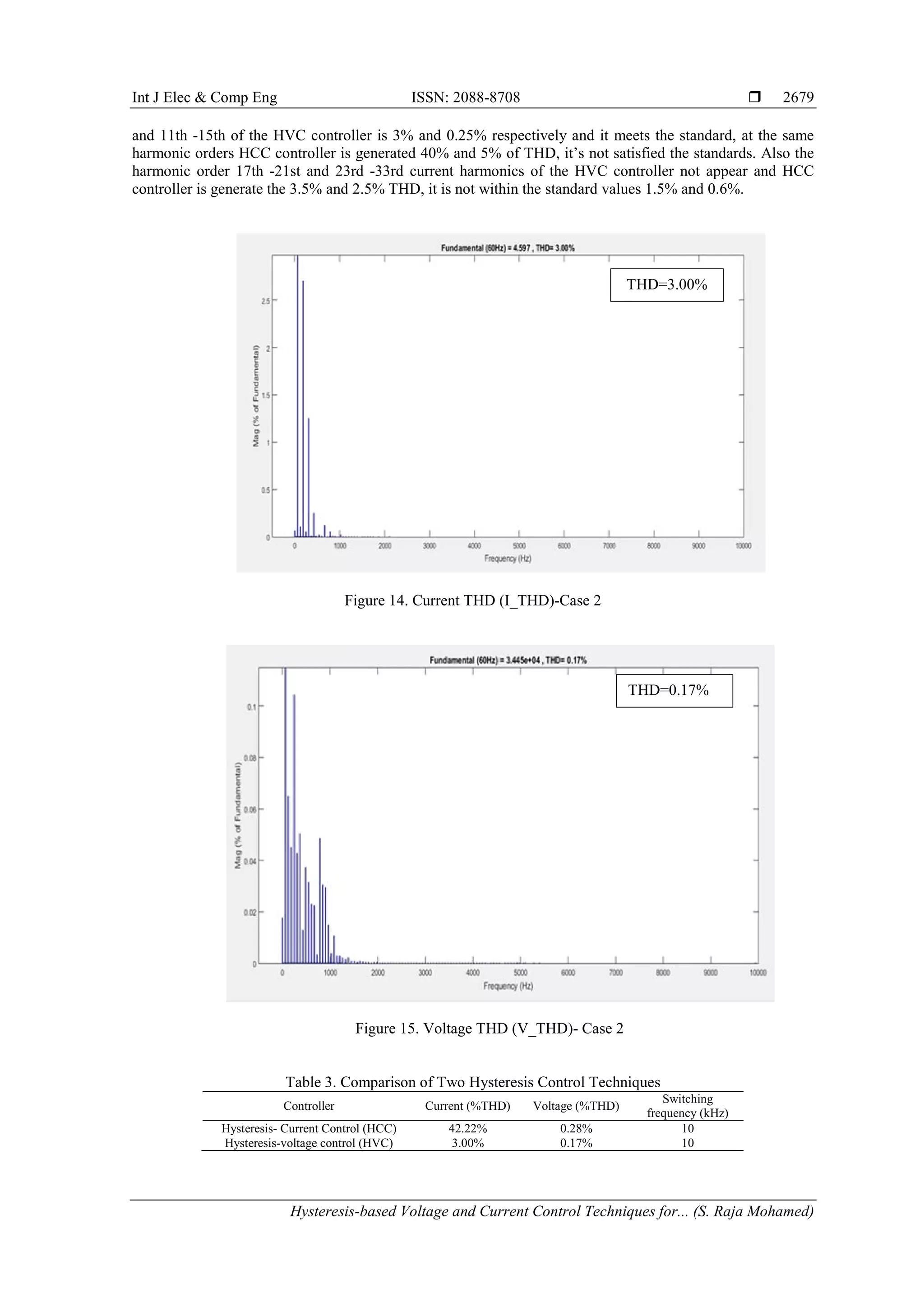
performance is affected often by change of magnitude, frequency, voltage dips, transient issues occur in a 3-](https://image.slidesharecdn.com/v043okt1731des178989-13892-1-edufi-201117063738/75/Hysteresis-based-Voltage-and-Current-Control-Techniques-for-Grid-Connected-Solar-Photovoltaic-Systems-Comparative-Study-1-2048.jpg)
![ ISSN: 2088-8708
Int J Elec & Comp Eng, Vol. 8, No. 5, October 2018 : 2671 - 2681
2672
phase grid. The study recommended that further enhancements to the current loop can be made by using soft
computing and intelligent control schemes. In [4] a hybrid model predictive control (HMPC) system is
proposed to control a 2-level voltage source inverter (VSI) of the high power grid. The impacts of the
modelling error on the system stability and average switching frequency are analyzed. HMPC can keep the
average switching frequency maintain operational limit, whereas improving the stability. Modelling and
analysis of a grid connected solar PV system integrating shunt active power filter (APF) with different PWM
generation feeding the nonlinear load is presented in [5]. In this study to generate required PWM signal for
the inverter hysteresis current control and space vector modulation (SVPWM) control are employed. The
simulation result shows that SVPWM provide the better result. In [6] presents the performance of grid
connected inverter with three digital hysteresis controllers such as fixed and adjustable switching frequency
controllers and PI compensation loop. The study found that PI control loop is efficent method to reduce the
harmonics Since, fixed switching frequency controller, the sampling frequency, filter inductance hystresis
band parameters are influence on the output current harmonics of the system. In [7] presents the method to
mitigate the power quality problems voltage sag, voltage swell of the grid by hysteresis voltage control
technique is used in inverter of dynamic voltage restorer (DVR) with PV system. The study [8] propose the
adaptive hysteresis band current control method for the 5-level cascaded multilevel inverter connected
photovoltaic system. The study concluded that due to increasing the number of levels of the inverter further
reduces total harmonic distortion (THD) of the system.
The study [9] proposed the fuzzy as well as adaptive controller to control the inverter used in the
grid connected solar PV system. The study concluded that the fuzzy adaptive hysteresis current controller
results in acceptable switching frequency and limited harmonic content and is suitable for photovoltaic
system. In [10] presents the effect of solar irradiance frequent changes of the grid-connected PV System on
THD. The study found that THD value increases when irradiance levels are decreasing. Unlike the above
mentioned works, this paper investigate the performance of the grid connected solar PV system using
hysteresis based voltage and current control techniques under the variable irradiance and temperature
conditions. This paper is organized as follows. Section II detail explanation of the overview of the system.
Section III presents modelling of various components in the system. The details of the proposed controller
are given in section IV, Simulation results and analysis of the proposed system are given in section V.
Conclusions are drawn in section VI.
2. STRUCTURE OF GRID-TIED PV SYSTEM
A grid-tied PV system as shown in Figure 1 have four major components blocks are there (i) solar
PV array, (ii) power electronics interface (iii) Controller (iv) grid. The Solar PV array delivers variable DC
power to the DC-DC boost converter, boosted DC power convert into the AC power using inverter and
transfer to the grid. The both the power converters have separate control system for maximize the DC power
and synchronous the grid and inverter voltage and frequencies.
.
Figure 1. Grid-tied solar PV system
3. SYSTEM MODELLING
3.1. PV Array Model
The equiavalent circuit of the solar PV cell as illustration in Figure 2.](https://image.slidesharecdn.com/v043okt1731des178989-13892-1-edufi-201117063738/75/Hysteresis-based-Voltage-and-Current-Control-Techniques-for-Grid-Connected-Solar-Photovoltaic-Systems-Comparative-Study-2-2048.jpg)
![Int J Elec & Comp Eng ISSN: 2088-8708
Hysteresis-based Voltage and Current Control Techniques for... (S. Raja Mohamed)
2673
Figure 2. Equivalent circuit of a solar PV cell
PV cell equation is as shown in equation 1,
𝐼 = 𝐼 𝑝ℎ − 𝐼0 �𝑒�
𝑞(𝑣+𝑅𝑠𝐼)
𝐴𝐾𝑇
−1�
� − �
𝑉+𝑅𝑠𝐼
𝑅𝑠ℎ
� (1)
where Id-reverse saturation diode current; v-thermal voltage; N diode quality factor; Iph photo voltaic
current. The proportion of the photovoltaic current and light intensity as given in equation 2.
𝐼𝑝ℎ = 𝐼𝑟 (𝐼 𝑝ℎ𝑜/𝐼 𝑟𝑜
) (2)
where Iph0 is photo voltaic current under standard light intensity (Ir0) [11]. Solar PV cell Characteristic curves
are shown in Figure 3.
Figure 3. PV cell characteristics curve
3.2. Boost Converter Model
A simple boost Converter is as shown in Figure 4. It is used in solar PV system to boost the output
voltage, when panel generate the lesser than actual voltage (unregulated) during the irregular weather
conditions with help of maximum power point tracking techniques [12]. Under steady state operation,
𝑣𝑖𝑛 × 𝑡 𝑜𝑛 − (𝑣0 − 𝑣𝑖𝑛) × 𝑡 𝑜𝑓𝑓 = 0 (3)
𝑣𝑖𝑛 × 𝐷 × 𝑇 = (𝑣0 − 𝑣𝑖𝑛) × (1 − 𝐷) × 𝑇 (4)
𝑣0
𝑣 𝑖𝑛
=
1
(1−𝐷)
(5)](https://image.slidesharecdn.com/v043okt1731des178989-13892-1-edufi-201117063738/75/Hysteresis-based-Voltage-and-Current-Control-Techniques-for-Grid-Connected-Solar-Photovoltaic-Systems-Comparative-Study-3-2048.jpg)
![ ISSN: 2088-8708
Int J Elec & Comp Eng, Vol. 8, No. 5, October 2018 : 2671 - 2681
2674
Figure 4. DC-DC boost converter [11]
3.3. Three-Phase Voltage Source Inverter (VSI) Model
The schematic diagram for a basic 3-phase VSI as shown in Figure 5. Here inverter is to convert dc
voltage get from the solar PV cell via boost converter into the ac voltage. The inverter mathematical model
state-space equations are given in Equation 6.
(6)
𝑢 𝑛𝑜 = (𝑢 𝐴 + 𝑢 𝐵 + 𝑢 𝐶 )/3 (7)
𝑢 𝐴 , 𝑢 𝐵 and 𝑢 𝑐 are controlled with switching conditions (Si) according to equ (8). [12]
(8)
Figure 5. Schematic diagram of the 3-phase voltage source inverter with hysteresis controller [13]](https://image.slidesharecdn.com/v043okt1731des178989-13892-1-edufi-201117063738/75/Hysteresis-based-Voltage-and-Current-Control-Techniques-for-Grid-Connected-Solar-Photovoltaic-Systems-Comparative-Study-4-2048.jpg)
![Int J Elec & Comp Eng ISSN: 2088-8708
Hysteresis-based Voltage and Current Control Techniques for... (S. Raja Mohamed)
2675
4. CONTROLLERS DESIGN
4.1. MPPT Control Technique
Incremental Conductance (IC) type MPPT techniques is developed based on P-V characteristic
curve. During the vast irradiation changes environment other MPPT techniques are fail to track the maximum
power. This problem solved by the IC method, it produces more energy and enhance the tracking time.
Figure 6 illustrate the IC method MPPT procedure. [14-15]. Equation 9, 10 and 11 show the mathematical
equation of the IC method. Maximum power condition is dp/dv=0
Power=v*i (9)
d(v*i)/dv=i+v*di/dv=0 (10)
di/dv=-i/v (11)
Figure 6.Incremental conductance MPPT[14-15]
4.2. Hysteresis Control Techniques
Hysteresis controller designed based on the properly selected hysteresis band (HB) fixed both of
side of the signal representing the preferred output waveform. Actually the control circuit generates the
desired magnitude and frequency reference sine wave signal, and it is compared with the actual input signal
by using the comparator. Switch status as shown in Table 1.
Table 1. 3-Phase Inverter Switching Logic Based on Hysteresis band (HB)
Comparator output signal status Switch Status
Exceeds the upper band of HB
Upper switch of the leg is ON;
Lower switch of the leg OFF
Cross the lower limits of HB
Upper switch of the leg is OFF;
Lower switch of the leg is ON
This study two types of hysteresis based control techniques are applied (I) Hysteresis voltage control
(HVC) (ii) Hysteresis current control (HCC) for the performance evaluation of the grid-tied PV system. This
study two types of hysteresis based control techniques are applied (a) Hysteresis voltage control (HVC) (b)
Hysteresis current control (HCC) for the performance evaluation of the grid-tied PV system.
4.2.1. Hysteresis Voltage Control (HVC)
Hysteresis voltage control structure as shown in Figure 7. In this technique grid-PCC point phase
voltage measure and compare with reference voltage value, hysteresis voltage band desired based on the ∆v-
error value. If suppose ∆error reach upper band value lower IGBTs are ON, alternate the ∆ error reach lower
band upper level IGBT are ON. Hysteresis band voltage control as shown in Figure 7. The relation between
the switching frequency and hysteresis band as shown in equation 12
𝑇1 + 𝑇2 = 𝑇𝐶 = 1/𝑓𝑐(12) (12)
Here, Hysteresis band=VH-VL as shown in Figure 8 and the THD calculation as shown in Equation 13.](https://image.slidesharecdn.com/v043okt1731des178989-13892-1-edufi-201117063738/75/Hysteresis-based-Voltage-and-Current-Control-Techniques-for-Grid-Connected-Solar-Photovoltaic-Systems-Comparative-Study-5-2048.jpg)
![Int J Elec & Comp Eng ISSN: 2088-8708
Hysteresis-based Voltage and Current Control Techniques for... (S. Raja Mohamed)
2677
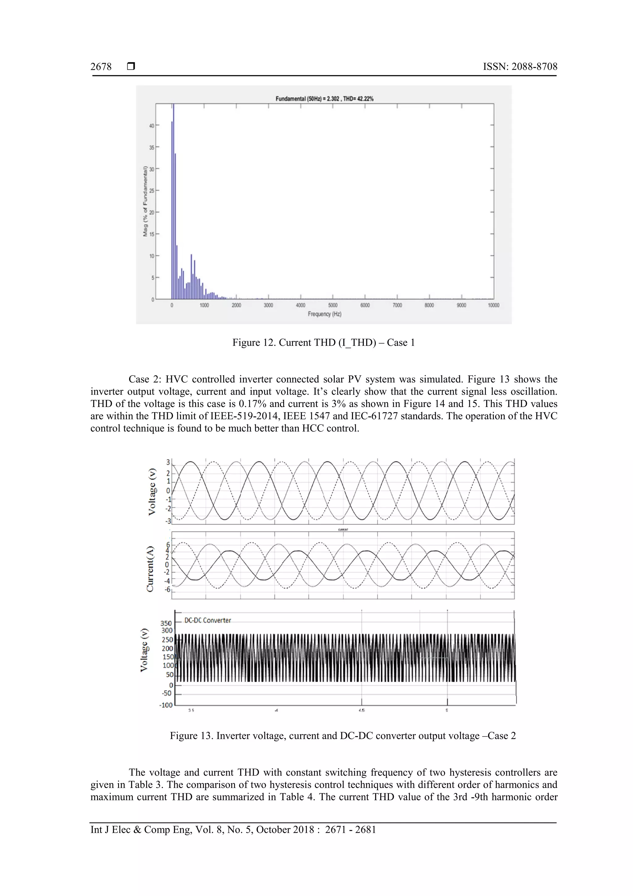
5. RESULTS AND DISCUSSION
The study model was developed and simulated using Simulink toolbox. The PV array is built based
on the Table 2 data’s and input signal temperature and irradiations ranges are set 250
C to 500
C and 250 to
1,000 W/m2 respectively. The developed study case Simulink model simulated and tested with proposed two
hysteresis control techniques (HCC and HVC) details are explain in this section.
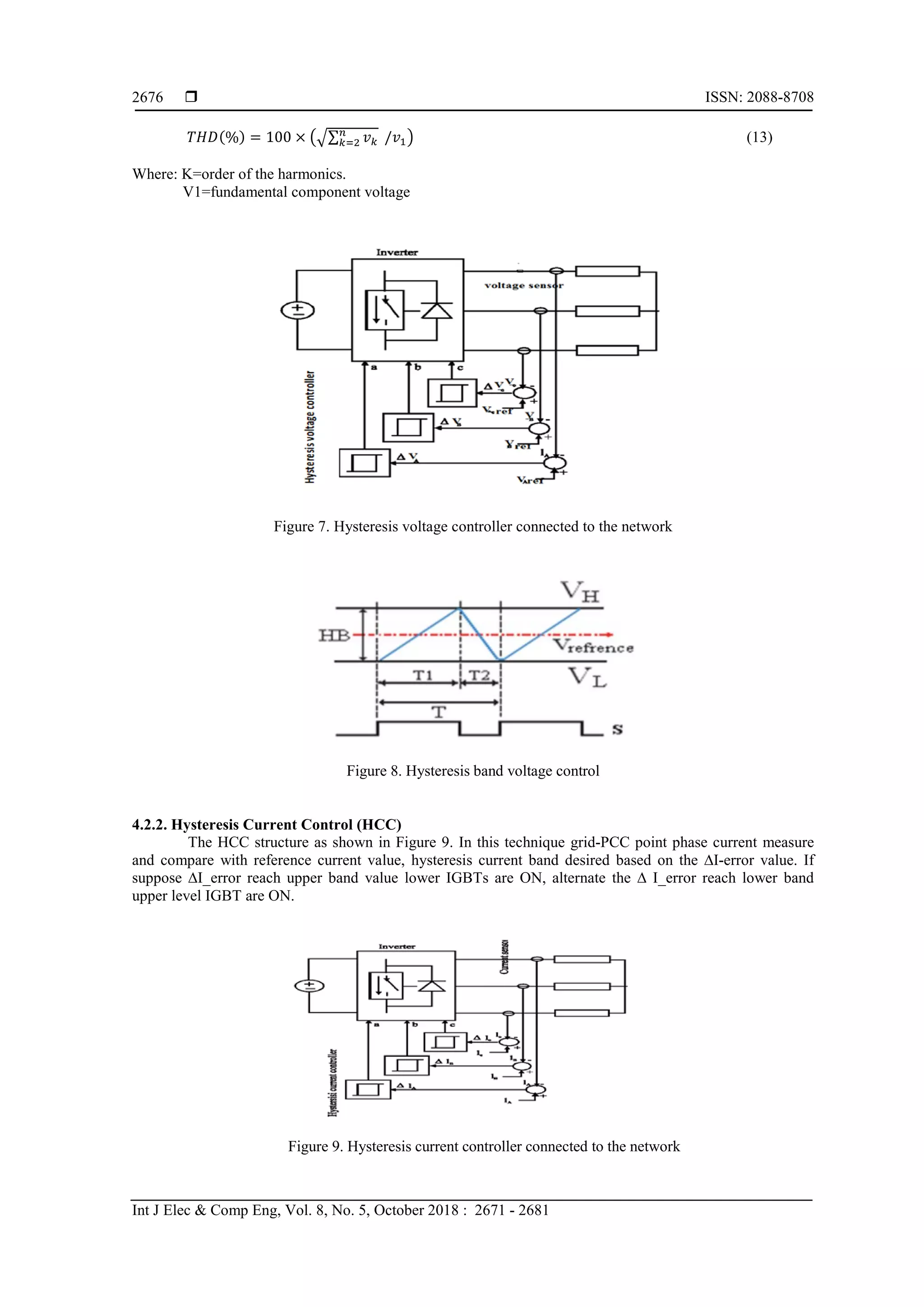
Case.1: HCC controlled inverter connected solar PV system was simulated. The inverter output
voltage, current and input voltage is shown in Figure 10. It’s clearly indicate that the inverter output current
signal is more distorted. THD of the voltage in this case is 0.28% and current is 42.42% as shown in Figure
11 and 12. The obtained results clearly indicate that voltage THD is within the IEEE-519-2014, IEEE-1547
and IEC61727 standards THD maximum limit 5% [16], [17], [18]. However, the current THD is exceed the
standards THD limit. The behaviour of the HCC control technique is found to be worst. Since hysteresis
current control, harmonics are wide spread from low to high frequency range.
Table 2. The Description of Study Case Solar PV System
Parameters Specifications
PV Array Data
Parallel string=7
Series connected modules per string=5
PV Module Data Name: Sun Power SPR-305-WHT-D
Cells per module(Ncell) 96
Maximum power (W) 305.226w
OCC voltage (Voc) (V) 64.2V
SCC current (ISC)(A) 5.96A
Figure 10. Inverter output voltage, output current and input voltage (HCC control)
Figure 11. Voltage THD (V_THD)-Case 1](https://image.slidesharecdn.com/v043okt1731des178989-13892-1-edufi-201117063738/75/Hysteresis-based-Voltage-and-Current-Control-Techniques-for-Grid-Connected-Solar-Photovoltaic-Systems-Comparative-Study-7-2048.jpg)
![ ISSN: 2088-8708
Int J Elec & Comp Eng, Vol. 8, No. 5, October 2018 : 2671 - 2681
2680
Table 4. Comparison of Two Hysteresis Control Techniques with Order of the Harmonics
IEC-61727 Standard Study system with (HVC)
Study system with
(HCC)
Nominal Power 10KW 10KW 10KW
*H
( nth
)
THD (%)
*H
(nth)
THD
(%)
*H
(nth)
THD
(%)
Harmonic current
limits
3-9 4 3-9 3% 3-9 40
11-15 2 11-15 0.25% 11-15 5
17-21 1.5 Not appear -- 17-21 3.5
23-33 0.6 Not appear -- 23-33 2.5
Maximum current
THD
5% 3% 42.42%
6. CONCLUSION
The performance of the two proposed controller techniques: hysteresis voltage controller and
hysteresis current controller has been investigated. The PV array modelling, inverter circuit topology, control
algorithm and implementation procedures are analyzed in detail. The competency of the proposed hysteresis
controllers has been demonstrated through the results of the simulation and validated with the IEEE 519-
2014, IEEE-1547 and IEC-61727 standards. This study concludes based on the results HVC controller used
in inverter is suitable for grid connected solar photovoltaic system to avoid the power quality problem
REFERENCES
[1] A. Rajapakse, D. Muthumuni, and N. Perera.Grid integration of renewable energy systems.in Renewable Energy,
InTech.2009:109-131.
[2] Porasad Y, Hosseinzadeh H. Comparison of voltage control and current control methods in grid connected
inverters. Journal of Applied Sciences. 2008;8(4):648-53.
[3] A F Jabbar, M Mansor.Current control loop of 3 phase grid-connected inverter. IOP Conference Series: Earth and
Environmental Science.2013.
[4] Arul Kumar K, Vijayakumar D, Palanisamy K. Recent advances and control techniques in grid connected PV
system. A review. International Journal of Renewable Energy Research (IJRER). 2016 Sep 6;6(3):1037-49.
[5] Ibrahim Z, et al., Performance investigation of photovoltaic grid connection for shunt active power filter with
different pwm generation. Journal of Theoretical & Applied Information Technology. 2013 Nov 20;57(2).
[6] Elsaharty MA, Hamad MS, Ashour HA. Digital hysteresis current control for grid-connected converters with LCL
filter. IECON 2011-37th Annual Conference on IEEE Industrial Electronics Society 2011 Nov 7 (pp. 4685-4690).
[7] Ali SY, Suneeta K. Simulation of the hysteresis voltage control technique in the pv based dynamic voltage restorer
for power quality improvement with induction motor drive. International Journal of Electrical and Electronics
Engineering Research (IJEEER).2015;5(1) :95-106.
[8] Punitha K, Devaraj D, Sakthivel S. Adaptive hysteresis current control of inverter for solar photovoltaic
applications. International Journal of Innovative Technology & Creative Engineering. 2011 Mar 3;1(3):25-33.
[9] Devaraj D, Sakthivel S, Punitha K. Fuzzy adaptive hysteresis band current controller for solar photovoltaic inverter.
In Advanced Materials Research 2012 (Vol. 403, pp. 4991-4999). Trans Tech Publications.
[10] Ayub M, Gan CK, Kadir AF. The impact of grid-connected PV systems on Harmonic Distortion. In Innovative
Smart Grid Technologies-Asia (ISGT Asia), IEEE 2014 May 20: 669-674).
[11] Louzazni M, Aroudam EH, Yatimi H. Modeling and simulation of a solar power source for a clean energy without
pollution. International Journal of Electrical and Computer Engineering. 2013 Aug 1;3(4):568.
[12] Erickson RW, Maksimovic D. Fundamentals of power electronics. Springer Science & Business Media; 2007.
[13] Isen E, Bakan AF. Comparison of hysteresis controlled three-wire and split-link four-wire grid connected inverters.
In Electrical Engineering/Electronics, Computer, Telecommunications and Information Technology (ECTI-CON),
2011 8th International Conference on 2011 May 17:727-730.
[14] Selvan S, Nair P, Umayal U. A Review on Photo Voltaic MPPT Algorithms. International Journal of Electrical and
Computer Engineering. 2016 Apr 1;6(2):567.
[15] Nandurkar SR, Rajeev M. Design and Simulation of Three Phase Inverter for Grid Connected Photovoltaic
systems. In 23rd annual IEEE Applied Power Electronics Conference and Exposition,2012:80–83.
[16] Langella R, Testa A. IEEE Recommended Practice and Requirements for Harmonic Control in Electric Power
Systems.
[17] IEEE Standards Association. IEEE 1547 standard for interconnecting distributed resources with electric power
systems. IEEE Standards Association, Piscataway. 2003.
[18] Photovoltaic IE. Systems. Characteristics of the Utility Interface. IEC Std. 2004 Jan: 61:727.](https://image.slidesharecdn.com/v043okt1731des178989-13892-1-edufi-201117063738/75/Hysteresis-based-Voltage-and-Current-Control-Techniques-for-Grid-Connected-Solar-Photovoltaic-Systems-Comparative-Study-10-2048.jpg)