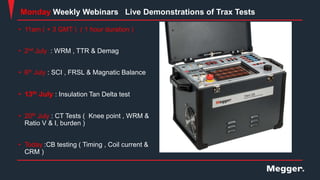
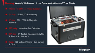
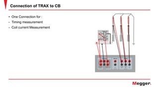
Jaafar Aldurazi
Sales & Application Engineer
Live demo on TRAX part 5 : HV
Circuit breaker testing (Contact
resistance, Timing, Coil current)
Presenter
 Jaafar Aldurazi
• Applications Engineer
• Megger Middle East, Bahrain
Today’s Presenter
 Send us your questions and comments during the presentation
Q&A
• 11am ( + 3 GMT ) ( 1 hour duration )
• 2nd July : WRM , TTR & Demag
• 6th July : SCI , FRSL & Magnatic Balance
• 13th July : Insulation Tan Delta test
• 20th July : CT Tests ( Knee point , WRM &
Ratio V & I, burden )
• Today :CB testing ( Timing , Coil current &
CRM )
Monday Weekly Webinars Live Demonstrations of Trax Tests
Scan QR code using Mobile Camera
Part 1
WRM
Demag
TTR
Part 2
SCI
FRSL
Magnetic Balance
Scan QR code using Mobile Camera
Part 3
Tan Delta
DFR
Tip Up
Part 4
Timing for CB
Coil current of CB
Contact resistance
 Cirecuit Breakers Fundamental
 Testing requirments
 Live testing using TRAX220 + Substation Software
Agenda
Low Voltage CBs
• Below 1000V
• Will trip on own when there is too much
current
• Timing test is performed via current
injection at actual current levels
Medium/High Voltage CBs
• Greater than 1000V
• Cannot trip on own, needs external signal
to trip
• Timing test performed via time and travel
analyzer at low currents
Cirecuit Breakers Fundamental
4
Typical Circuit Breaker-Single break per phase
The contact is operated by
mechanically separating the
contacts. Common insulation media
are oil, air, vacuum and SF6.
Open and close operations are
obtained by releasing energy stored
in a spring. The spring is controlled
by a coil and charged by a electrical
motor.
Connector
CB chamber where
the contact is
Operating mechanism
and control unit, auxiliary
contacts, spring.
Isolation to
earth
Connector
5
Typical Circuit Breaker-Multiple breaks per phase
 Grading capacitors in parallel
to divide voltage equally.
 Synchronization is important.
Connector Connector
 One contact can not break
400 kV under load.
CB chamber
where the
contact is
Isolation to
earth
Operating mechanism
and control unit, auxiliary
contacts, spring.
Gas Insulated switchgear (GIS)
 Everything is inside Gas Champers
(Usually SF6 GAS)
 Compact , usually Fitted indoors
 Slightly Difficult for Maintenance
operations
 When Energized Substation only access
through Earth links
Operating mechanism
and control unit
CB Chambers
Earth Links
Medium Voltage (MV) Circuit Breakers
 Usually from 400 V to 40 kV
Application
 Compact , usually Fitted in
Cabinets
 Ability to Rack Out of Cabinets for
Maintenance
CB Chambers
Operating mechanism
and control unit
10
Circuit Breaker Testing
Basic
 Contact resistance
 Contact timing
 Travel (stroke, speed,
damping, penetration)
 Operating coil current
 Minimum trip voltage
Advanced (diagnostic)
 Dynamic Resistance Measurement
 First Trip Test (On-Line)
Special
 Pressure (air blast breakers)
 Vacuum check (vacuum breakers)
 SF6 related Tests (Purity ,
Pressure , Etc)
 Insulation Tests
11
Contact Resistance
 Verify low contact resistance (micro ohm).
 High current for accuracy.
 Test current (DC):
• Minimum 100 A (IEEE)
• IEC standard requires a current of at least 50 ADC
• +10% of rated current (recommended)
12
Contact Resistance 4-wire method
>100 A
28 µΩ
Generate high current with 2
leads and measure voltage drop
with 2 separate leads.
Ability to Do Dual Ground
13
Contact Timing
 Close/open time also CO, O-C , O-CO
• Values are usually available in the CB manual
 Breaker synchronization (phase vs. phase)
• < 1/4 cycle @ close operation (IEC62271-100)
• < 1/6 cycle @ open operation (IEC62271-100)
 Phase synchronization (interrupters inside phase)
• < 1/8 cycle (IEC62271-100)
 Correct timing between main & resistor
contact(PIR Contacts)
 Aux contacts lead/lag time
16
Motion measurements
17
Trip/CloseCoil Measurement
 Recording the coil currents during breaker operation
 Armature time(coil Time)
 Max current
 Duration
 Coil Resistance
 Voltage During Operation
18
Coil Current Trace
Mechanism
Release
Open Coil
motion Main Contacts motion
Mechanism Motion
|--------Coil Motion----------
|
Locked
Open
comma
nd
----------Auxiliary contact opened----------
|
-------------Mechanism Motion-------------
|
Detect
Coil time vs Mechanism Time
Bad Coil or Bad Mechanism
No additional clamp needed
Control module direct measures
Current
recordin
g
19
Minimum Operating Voltage
 Verify that the breaker operates at the minimum
voltage (IEC 60694)
• CLOSE: 85% of rated operating voltage (AC/DC)
• OPEN: 70% of rated operating voltage (DC)
• OPEN: 85% of rated operating voltage (AC)
 11am ( + 3 GMT ) ( 1 hour duration )
 2nd July : WRM , TTR & Demag
 6th July : SCI , FRSL & Magnatic
Balance
 13th July : Insulation Tan Delta test
 20th July : CT Tests ( Knee point , WRM
& Ratio V & I, burden )
 Today :CB testing ( Timing , Coil current
& CRM )
Monday Weekly Webinars Live Demonstrations of Trax Tests
Scan QR code using Mobile Camera
Part 1
WRM
Demag
TTR
Part 2
SCI
FRSL
Magnetic Balance
Scan QR code using Mobile Camera
Part 3
Tan Delta
DFR
Tip Up
Part 4
Timing for CB
Coil current of CB
Contact resistance
25
Advanced Testing Unit
Webinar - Introduction to HV CB testing. Products, testing functions, features,benefits
By Ali Husain
Live Demo
We Need TRAX unit + Substation testing Software activated
Test Object
1- BRS – Breaker Simulator
- 1x break per phase
- Common mechanism
Test Conducted
1-Timing
2- Coil current
3- Contact Resistance
• One Connection for :
- Timing measurement
- Coil current Measurement
Connection of TRAX to CB
Questions?
 Send us your questions and comments during the presentation
Q&A
Contact Information
Presenter
Jaafar Aldurazi
Jaffer.aldurazi@megger.com
Survey and Contact Information

HV CB testing.pdf

  • 1.
    Jaafar Aldurazi Sales &Application Engineer Live demo on TRAX part 5 : HV Circuit breaker testing (Contact resistance, Timing, Coil current)
  • 2.
    Presenter  Jaafar Aldurazi •Applications Engineer • Megger Middle East, Bahrain Today’s Presenter
  • 3.
     Send usyour questions and comments during the presentation Q&A
  • 4.
    • 11am (+ 3 GMT ) ( 1 hour duration ) • 2nd July : WRM , TTR & Demag • 6th July : SCI , FRSL & Magnatic Balance • 13th July : Insulation Tan Delta test • 20th July : CT Tests ( Knee point , WRM & Ratio V & I, burden ) • Today :CB testing ( Timing , Coil current & CRM ) Monday Weekly Webinars Live Demonstrations of Trax Tests
  • 5.
    Scan QR codeusing Mobile Camera Part 1 WRM Demag TTR Part 2 SCI FRSL Magnetic Balance
  • 6.
    Scan QR codeusing Mobile Camera Part 3 Tan Delta DFR Tip Up Part 4 Timing for CB Coil current of CB Contact resistance
  • 7.
     Cirecuit BreakersFundamental  Testing requirments  Live testing using TRAX220 + Substation Software Agenda
  • 8.
    Low Voltage CBs •Below 1000V • Will trip on own when there is too much current • Timing test is performed via current injection at actual current levels Medium/High Voltage CBs • Greater than 1000V • Cannot trip on own, needs external signal to trip • Timing test performed via time and travel analyzer at low currents Cirecuit Breakers Fundamental
  • 9.
    4 Typical Circuit Breaker-Singlebreak per phase The contact is operated by mechanically separating the contacts. Common insulation media are oil, air, vacuum and SF6. Open and close operations are obtained by releasing energy stored in a spring. The spring is controlled by a coil and charged by a electrical motor. Connector CB chamber where the contact is Operating mechanism and control unit, auxiliary contacts, spring. Isolation to earth Connector
  • 10.
    5 Typical Circuit Breaker-Multiplebreaks per phase  Grading capacitors in parallel to divide voltage equally.  Synchronization is important. Connector Connector  One contact can not break 400 kV under load. CB chamber where the contact is Isolation to earth Operating mechanism and control unit, auxiliary contacts, spring.
  • 11.
    Gas Insulated switchgear(GIS)  Everything is inside Gas Champers (Usually SF6 GAS)  Compact , usually Fitted indoors  Slightly Difficult for Maintenance operations  When Energized Substation only access through Earth links Operating mechanism and control unit CB Chambers Earth Links
  • 12.
    Medium Voltage (MV)Circuit Breakers  Usually from 400 V to 40 kV Application  Compact , usually Fitted in Cabinets  Ability to Rack Out of Cabinets for Maintenance CB Chambers Operating mechanism and control unit
  • 13.
    10 Circuit Breaker Testing Basic Contact resistance  Contact timing  Travel (stroke, speed, damping, penetration)  Operating coil current  Minimum trip voltage Advanced (diagnostic)  Dynamic Resistance Measurement  First Trip Test (On-Line) Special  Pressure (air blast breakers)  Vacuum check (vacuum breakers)  SF6 related Tests (Purity , Pressure , Etc)  Insulation Tests
  • 14.
    11 Contact Resistance  Verifylow contact resistance (micro ohm).  High current for accuracy.  Test current (DC): • Minimum 100 A (IEEE) • IEC standard requires a current of at least 50 ADC • +10% of rated current (recommended)
  • 15.
    12 Contact Resistance 4-wiremethod >100 A 28 µΩ Generate high current with 2 leads and measure voltage drop with 2 separate leads. Ability to Do Dual Ground
  • 16.
    13 Contact Timing  Close/opentime also CO, O-C , O-CO • Values are usually available in the CB manual  Breaker synchronization (phase vs. phase) • < 1/4 cycle @ close operation (IEC62271-100) • < 1/6 cycle @ open operation (IEC62271-100)  Phase synchronization (interrupters inside phase) • < 1/8 cycle (IEC62271-100)  Correct timing between main & resistor contact(PIR Contacts)  Aux contacts lead/lag time
  • 17.
  • 18.
    17 Trip/CloseCoil Measurement  Recordingthe coil currents during breaker operation  Armature time(coil Time)  Max current  Duration  Coil Resistance  Voltage During Operation
  • 19.
    18 Coil Current Trace Mechanism Release OpenCoil motion Main Contacts motion Mechanism Motion |--------Coil Motion---------- | Locked Open comma nd ----------Auxiliary contact opened---------- | -------------Mechanism Motion------------- | Detect Coil time vs Mechanism Time Bad Coil or Bad Mechanism No additional clamp needed Control module direct measures Current recordin g
  • 20.
    19 Minimum Operating Voltage Verify that the breaker operates at the minimum voltage (IEC 60694) • CLOSE: 85% of rated operating voltage (AC/DC) • OPEN: 70% of rated operating voltage (DC) • OPEN: 85% of rated operating voltage (AC)
  • 21.
     11am (+ 3 GMT ) ( 1 hour duration )  2nd July : WRM , TTR & Demag  6th July : SCI , FRSL & Magnatic Balance  13th July : Insulation Tan Delta test  20th July : CT Tests ( Knee point , WRM & Ratio V & I, burden )  Today :CB testing ( Timing , Coil current & CRM ) Monday Weekly Webinars Live Demonstrations of Trax Tests
  • 22.
    Scan QR codeusing Mobile Camera Part 1 WRM Demag TTR Part 2 SCI FRSL Magnetic Balance
  • 23.
    Scan QR codeusing Mobile Camera Part 3 Tan Delta DFR Tip Up Part 4 Timing for CB Coil current of CB Contact resistance
  • 24.
    25 Advanced Testing Unit Webinar- Introduction to HV CB testing. Products, testing functions, features,benefits By Ali Husain
  • 25.
    Live Demo We NeedTRAX unit + Substation testing Software activated Test Object 1- BRS – Breaker Simulator - 1x break per phase - Common mechanism Test Conducted 1-Timing 2- Coil current 3- Contact Resistance
  • 26.
    • One Connectionfor : - Timing measurement - Coil current Measurement Connection of TRAX to CB
  • 27.
  • 28.
     Send usyour questions and comments during the presentation Q&A
  • 29.