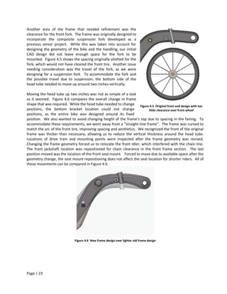
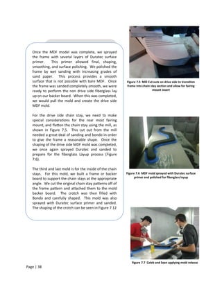
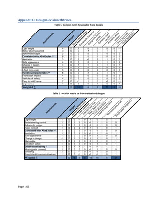
The report details the design and construction of a human-powered vehicle (HPV) for Cal Poly's entry in the ASME Human Powered Vehicle Challenge, focusing on a carbon fiber-epoxy frame and an innovative drive train. The team collaborated with HPV club leadership to establish engineering specifications, resulting in a prototype that achieves a 50% weight reduction compared to previous designs. Final designs and manufacturing plans, alongside analysis of the drive train and frame, have been documented, though further testing is required to validate performance.
![Chapter 1: Introduction
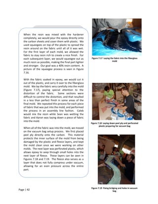
For our first project at Bicycle Technical Innovations, we have designed a new bike for Cal Poly’s 2009
Human Powered Vehicle team. Our bike will be used in the 2009 American Society of Mechanical
Engineers Human Powered Vehicle competition, in Portland, Oregon. We have worked closely with the
HPV club, their racers, and an Aerospace Engineering senior project group to determine the necessary
engineering specifications and concepts for our new vehicle. The final bike will be a working prototype
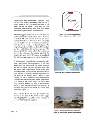
that is integrated with other components specified by the HPV team. Our goals, discussed in greater
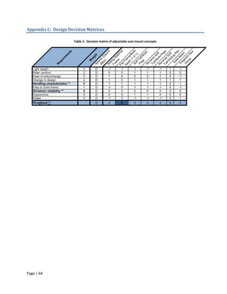
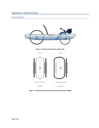
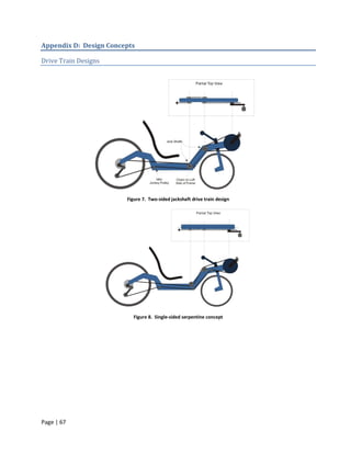
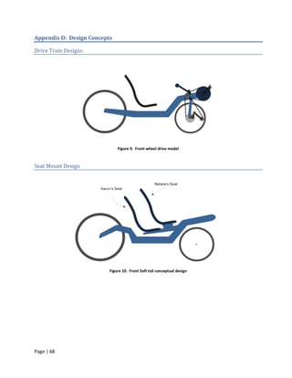
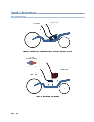
depth later in this report, are to design and build a new, lighter frame, more reliable drive train, and an
easily adjustable seat mount. By completing these goals, we plan to deliver a high quality vehicle that
performs exceptionally well at the ASME competition.
1.1 Nomenclature
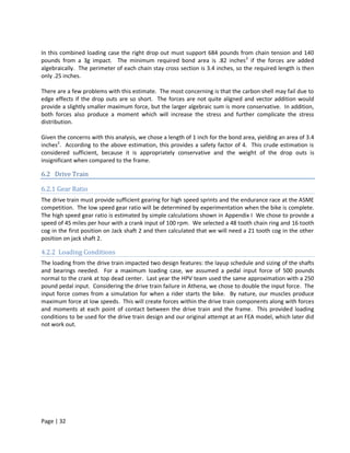
This document contains many terms that are very common in the cycling industry and the Human
Powered Vehicle world. Figure 1.1 shows many of these terms to help clarify any parts or terms that may
be discussed throughout this report.
Figure 1.1 Bicycle terminology
1.2 Background
Competition Details
To begin our research, we considered the format of the competition and reviewed the body of rules
relating to vehicle design and construction. The ASME judges have provided a detailed description of the
competition formats and a list of rules [1]. The HPV Challenge involves three distinct areas of competition:
a design category and two different races. Success in the competition will require excellent performance in
all three areas.
The first category of the competition, design, begins with the submission of a report several weeks before
the actual event. Student teams must prepare and submit technical reports detailing the design and
Page | 8](https://image.slidesharecdn.com/hpvseniorprojectreport2009-1250197658912-phpapp02/85/HPV-Senior-Project-Report-2009-9-320.jpg)
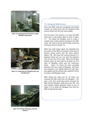
![Chapter 6: Analysis
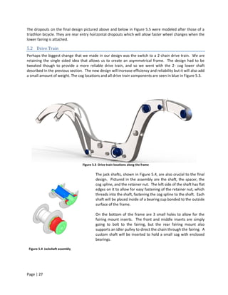
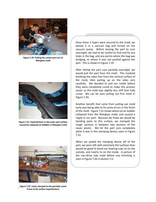
6.1 Frame
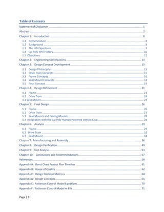
The frame has three basic requirements. It must provide: good handling, stiffness, and sufficient strength.
In order to meet these goals, we used an existing mathematical model of bicycle controllability and
classical lamination theory.
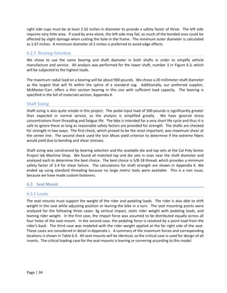
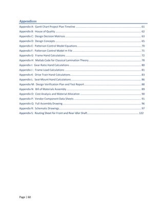
6.1.1 Handling and Controllability Analysis
In recent years, the Cal Poly HPV designs have provided exceptional handling characteristics. Many of the
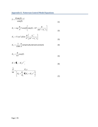
team riders have provided feedback comparing some of these vehicles. We have also used the Patterson
Control Model (PCM) to quantify the response of the various bikes. The qualitative rider input was used to
interpret our results so that we could choose the best compromise of handling qualities. This model is
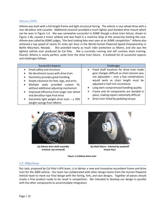
based on several critical parameters that are shown in Table 6.1.
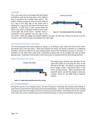
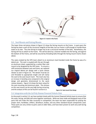
The Patterson Control Model provides two very useful tools for analyzing the handling of a bicycle. The
first is the control spring as a function of velocity, which indicates the force feedback felt through the
handle bars. The positive values show a control reversal and tend to make a bike unstable and negative
values tend to make a bike stable. In this case, the maximum value must be low and the transition to a
negative control spring must happen at very low speeds so that the bike stabilizes itself quickly. The
second tool is a graph of the control sensitivity as a function of velocity. Control sensitivity describes the
roll response of the bike compared to the rider’s intention. The basic equations of this model are shown
in Appendix E and the Mat lab code used is included as Appendix F. A full description of these tools is
beyond the scope of this report, but more information is available from references 3 and 4.
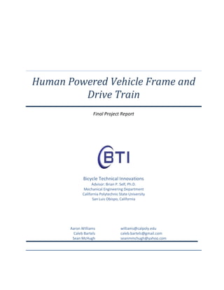
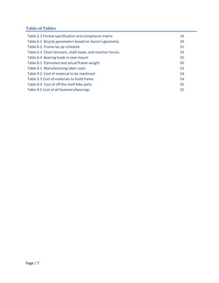
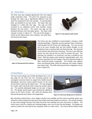
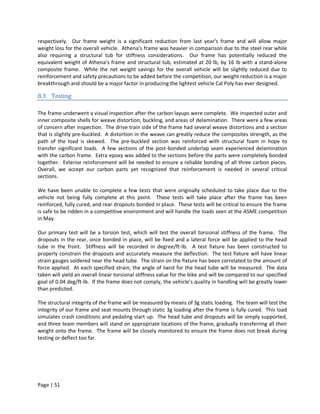
Table 6.1 Bicycle parameters based on Aaron's geometry
Parameter Units 2009 BTI Athena Matrix
Wheelbase A [m] 1.321 1.397 1.051
C.G. Position B [m] 0.838 0.874 0.531
C.G. Height h [m] 0.445 0.394 0.394
Head Tube Angle β [°] 12 12 12
Radius of Gyration Kx [m] 0.272 0.213 0.213
Control Radius Rh [m] 0.2 0.203 0.127
Front Wheel Radius R [m] 0.241 0.241 0.241
Offset e [m] -0.076 -0.076 -0.051
In particular, we chose to compare to Athena because the general configuration is the same as our design.
We reduced the control sensitivity slightly while retaining a similar control spring response. Decreasing
the control sensitivity will provide a ride that feels more stable and predictable and should ultimately lead
to better performance. Testing by W.B. Patterson showed that a control sensitivity of about 14 made for a
stable, comfortable ride. This line is shown on the graph for comparison. We have been careful to retain
a fairly high amount of control sensitivity so that the bike will still feel responsive and quick. We believe
that the HPV riders are exceptional bike handlers and will prefer higher control sensitivity.
Page | 29](https://image.slidesharecdn.com/hpvseniorprojectreport2009-1250197658912-phpapp02/85/HPV-Senior-Project-Report-2009-30-320.jpg)
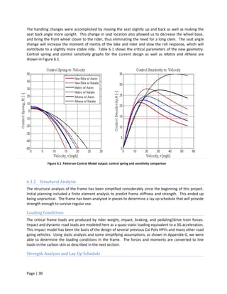
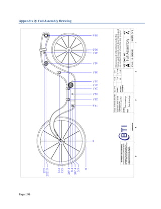
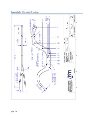
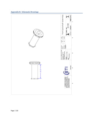
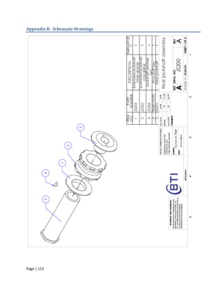
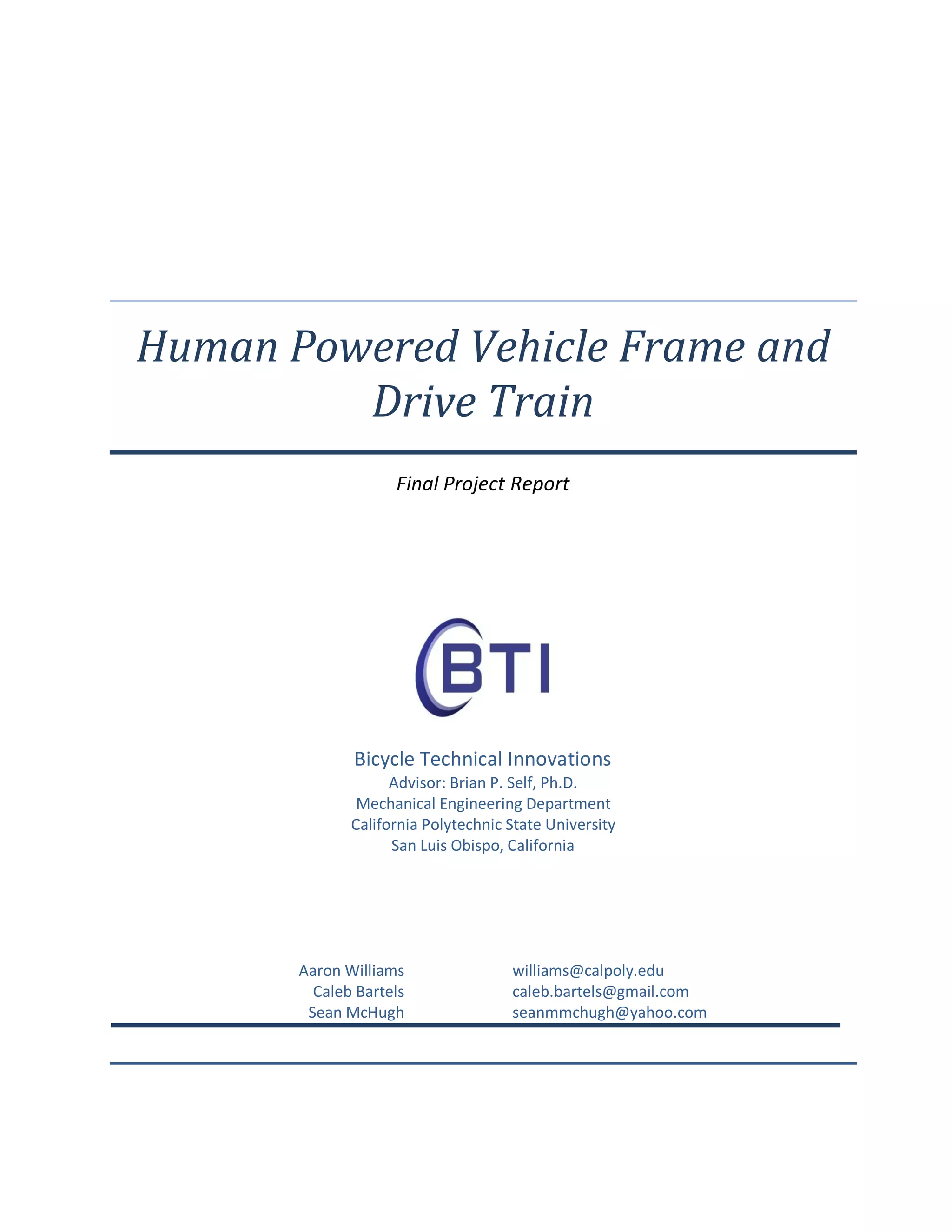
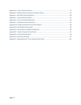
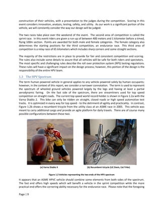
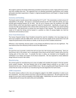
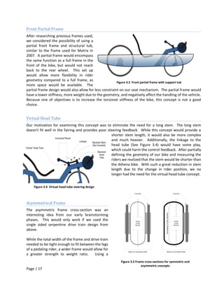
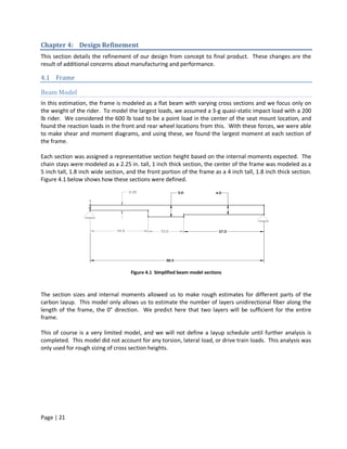
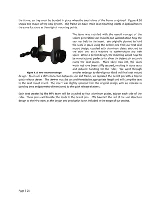
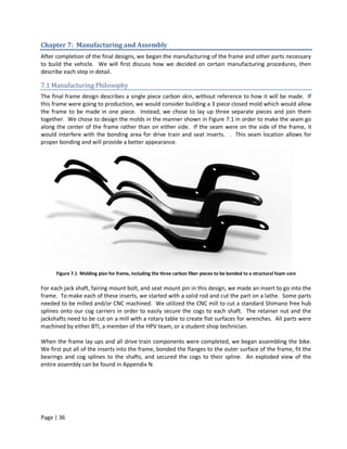
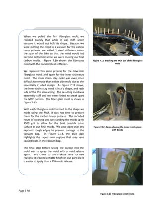
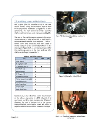
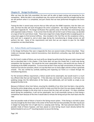
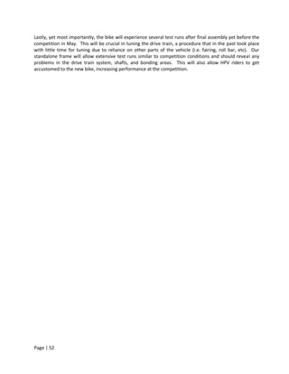
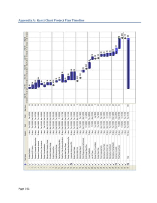
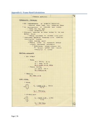
![Figure 6.2 Geometry diagram for drive train force analysis
Using the geometry shown above in Figure 4.3, we were able to calculate the reaction forces for each
shaft in the drive train based on the chain tension. The reactions for points 1, 2, and 3 are shown below in
Table 6.3. These correspond to the bottom bracket, front jackshaft, and rear jackshaft respectively.
Details regarding the geometry of Figure 6.2 can be found in Appendix J.
Table 6.3 Chain tensions, shaft loads, and reaction forces based on 500lbf Pedaling Force
Tension Vertical Shaft Loads Horizontal Shaft
Location [lb] [lb] Loads [lb]
1 855 -219 -827
2 855 -391 227
3 684 735 -73
The reactionary loads on the drive and non drive side of the frame were calculated from the vertical loads,
horizontal loads, and length of the shafts. This informed us where the critical sections were located and
what was the minimum force needed to design our bearing cup mounts. The critical load takes place at
location 3, on the drive side of the rear jackshaft. The skin of the frame experiences 1038 lb vertically and
411 lb horizontally. We designed around this loading case to ensure our drive train and frame would not
fail.
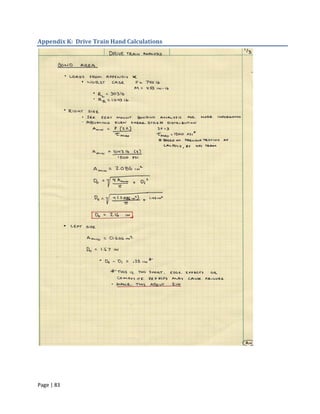
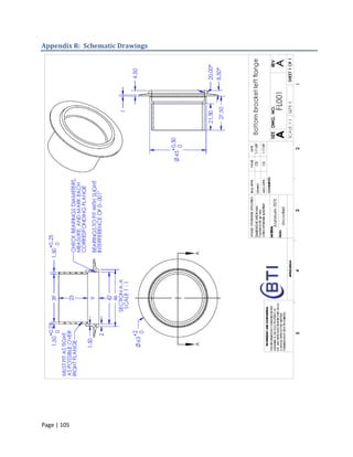
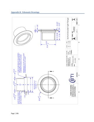
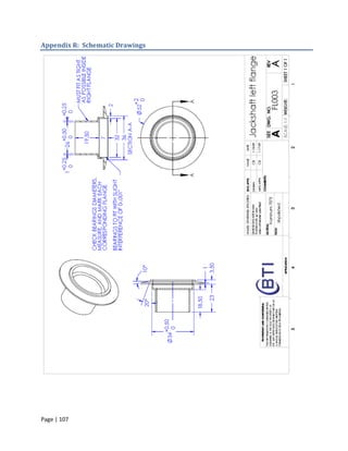
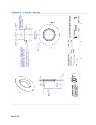
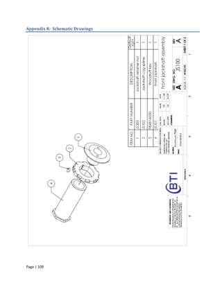
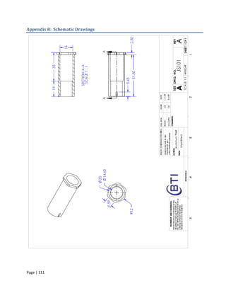
6.2.2 Bonding Area
The drive train shafts are bonded to the frame using round, tapered flanges. Adhesive bonding is a rapidly
developing field, and exact stress analysis of a particular bond is very difficult. To avoid excessive analysis,
we have used information from previous testing. The HPV performed careful testing of similar aluminum
bonds last year. The test data was reported as maximum average stress at joint failure. The drive train
cups will be similarly sized so an average shear stress approach is appropriate for design. Additionally, the
bonded flanges are tapered to reduce stress concentrations and smooth the shear stress distribution.
The analysis of a uniform stress distribution is used to determine the minimum outer diameter of the
bonded flanges. The right side cups will see significantly higher loads, estimated up to 740 pounds. The
Page | 33](https://image.slidesharecdn.com/hpvseniorprojectreport2009-1250197658912-phpapp02/85/HPV-Senior-Project-Report-2009-34-320.jpg)
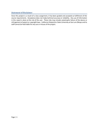
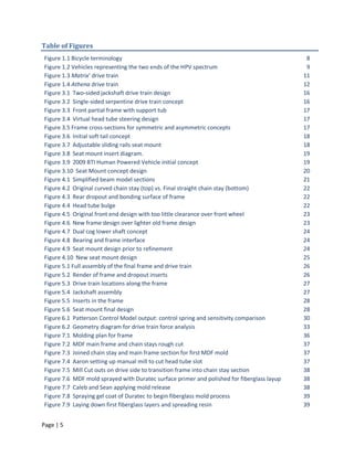
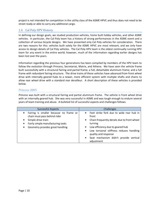
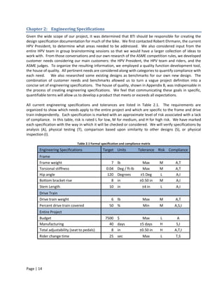
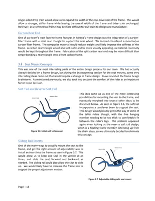
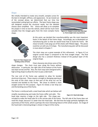
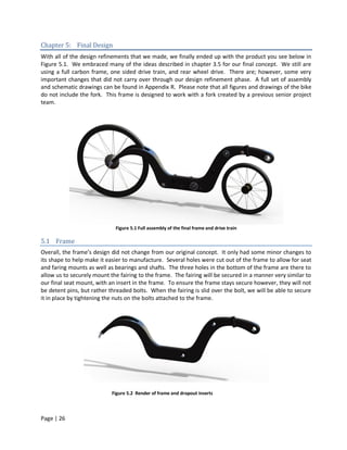
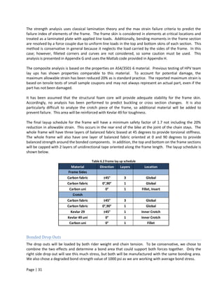
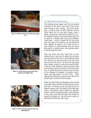
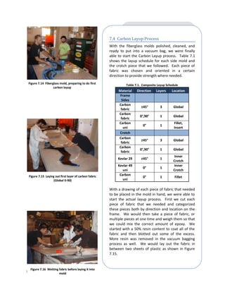
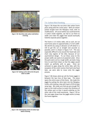
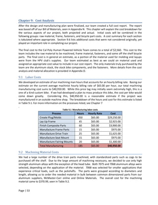
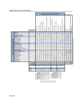
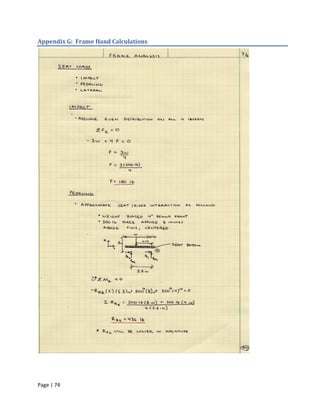
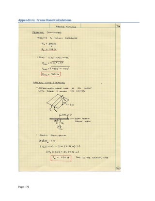
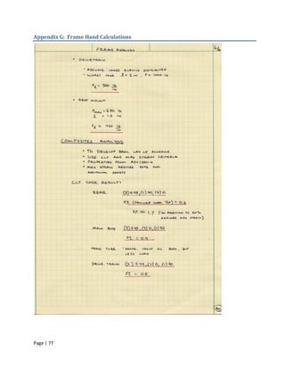
![Table 6.4 Bearing loads in seat mount
Maximum Force
Loading Case Location
Per Hole[lb]
3g Impact 150 all
Leaning or Cornering 630 each side
Max Pedal Force 460 rear
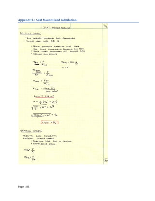
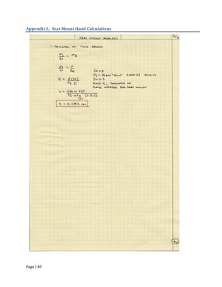
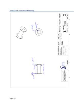
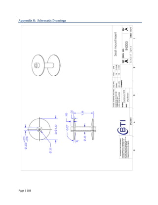
6.3.2 Sizing
This section provides a description of the analyses made to size components and finalize the seat mount
design.
Bond Area
As mentioned above, all inserts will be identical and all design is based on the highest load predicted.
These inserts, like the drop outs will be bonded to the frame skin with round, tapered flanges. The bond is
modeled as a simple lap shear joint with an even stress distribution. With a safety factor of 3 and
maximum shear strength of 1500 psi, the outer diameter of the seat insert flange must be at least 1.3
inches, providing 1.26 in2 of bonding area.
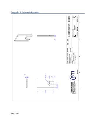
Bearing Surface
The seat mount will have an aluminum plate as a bearing surface. This plate is intended only as a bearing
surface and must be reinforced by additional structure. Accordingly, we have analyzed only bearing stress
in the plates.
The worst case load is 630 pounds per insert. These plates will be made of 7075 T6 aluminum sheet which
has an approximate yield strength of 76 ksi [8]. The plate was sized by assuming uniform distribution of
bearing stress and neglecting the clamping mechanism. Clamping force provides a more complex stress
state and allows some load to be transmitted via friction and surface traction. According to this simplified
analysis, shown in Appendix L, the plates must be 0.083 inches thick to provide a safety factor of 3.
Page | 35](https://image.slidesharecdn.com/hpvseniorprojectreport2009-1250197658912-phpapp02/85/HPV-Senior-Project-Report-2009-36-320.jpg)
![References
[1] Rules for the 2009 Human Powered Vehicle Challenge, ASME.org, 2008
[2] Dynamic Model of a Bicycle from Kinematic and Kinetic Considerations, Andrew Davol and Frank
Owen, California Polytechnic State University, San Luis Obispo
[3] Model of a Bicycle from Handling Qualities Considerations, Andrew Davol and Frank Owen,
California Polytechnic State University, San Luis Obispo
[4] The Chronicles of the Lords of the Chain Ring, W.B. Patterson
[5] Bicycling Science, 3rd ed, David G. Wilson, MIT Press, 2004
[6] High Tech Cycling, Edmond R. Burke, Human Kinetics, 2003
[7] Shigley’s Mechanical Engineering Design, Richard Budynas and J. Keith Nisbett, McGraw-Hill,
October 25, 2006
[8] Matweb. 2009. Automation Creations, Inc.. <htt[://www.matweb.com/>
Page | 59](https://image.slidesharecdn.com/hpvseniorprojectreport2009-1250197658912-phpapp02/85/HPV-Senior-Project-Report-2009-60-320.jpg)
![Appendix F: Patterson Control Model m File
% Patterson Control Model
% By Darryll Fletcher
clc; close all; clear all
% Parameters %
% New Bike || Matrix w/ Aaron || Athena w/Aaron ||
A =[ 1.321, 1.054, 1.397]; %Wheelbase Length [m]
B =[ 0.838, 0.531, 0.874]; %C.M. to Rear Hub [m]
h =[ 0.445, 0.394, 0.394]; %C.M. Height [m]
Beta =[ 13, 12, 12]; %Compliment of Head Tube Angle [∞]
k_x =[ 0.272, 0.213, 0.213]; %Radius of Gyration [m]
R_h =[ 0.2, 0.2032, 0.35]; %Handlebar Radius [m]
R =[ 0.241, 0.241, 0.241]; %Front Wheel Radius [m]
e =[ -.076, -0.051, -0.076]; %Offset [m]
m =[ 119.7, 119.7, 119.7]; %Combined Mass [kg]
g = 9.81; %Gravity [m/s^2]
Max_V = 55*0.44704; %Maximum Velocity [m/s]
ConstantMtx = [A,B,h,Beta,k_x,R_h,R,e,m];
ConstantNames = {'Wheelbase','C.M. to Rear','C.M. Height','Head Tube Angle'...
,'Radius of Gyration','Handlebar Radius','Front Wheel Radius','Offset','Combined Mass'};
Velocity = [0:Max_V/1000:Max_V];
for alpha = 1:length(A)
T(alpha) = (R(alpha)).*sind(Beta(alpha)) - e(alpha)./cosd(Beta(alpha)); % Track [m]
K_1(alpha)=(m(alpha).*g.*(B(alpha)./A(alpha)).*T(alpha).*cosd(Beta(alpha))).*(sind(Beta(alpha)) -
h(alpha).*T(alpha).*B(alpha)./(A(alpha).*(h(alpha).^2 + k_x(alpha).^2)));
K_2(alpha)=T(alpha).*(cos(Beta(alpha)).^2).*m(alpha).*(B(alpha)./A(alpha).^2).*(k_x(alpha).^2./(h(alpha).
^2 + k_x(alpha).^2));
K_3(alpha) = 1/1500; %[m/N]
K_4(alpha) = B(alpha)./(h(alpha).*A(alpha)).*cos(Beta(alpha));
K(:,alpha) = (K_1(alpha) - K_2(alpha).*Velocity.^2); %Control Spring
Con_Sens(:,alpha) = (K_4(alpha).*Velocity)./(R_h(alpha) + (K_3(alpha)/R_h(alpha)).*(-K_1(alpha) +
K_2(alpha).*Velocity.^2)); %Control Sensitivity [-]
End
Page | 71](https://image.slidesharecdn.com/hpvseniorprojectreport2009-1250197658912-phpapp02/85/HPV-Senior-Project-Report-2009-72-320.jpg)
![Appendix H: Matlab Code for Classical Lamination Theory
% Simple CLT File for i = 2 : imax
% Written by Mello, J.D., Ph.D. h(i) = h(i-1) + l(i-1,2);
clear all end
close all
clc %loop over each ply to integrate the ABD matrices
for i = 1:n
%set up a diary file
diary CLTng.dat %ply material ID
%units are US customary (lb, in, E in psi) mi=l(i,3);
% total laminate definition in matrix below v21 = E(mi,2)*E(mi,3)/E(mi,1);
% [ply angles, thicknesses, matl. #] d = 1 - E(mi,3)*v21;
%Set up for two materials
%Q12 matrix
% Data in there now is Q = [E(mi,1)/d v21*E(mi,1)/d 0;
%1-carbon E(mi,3)*E(mi,2)/d E(mi,2)/d 0;
%2-Eglass 0 0 E(mi,4)];
% Laminate is defined in this matrix little "L" or l (sorry it looks like %ply angle in radians
a one in default font) a1=l(i,1)*pi/180;
disp('Laminate:')
disp('angle thick matl #') %Form transformation matrices T1 for ply
%to change format of l output to default T1 = [(cos(a1))^2 (sin(a1))^2
format 2*sin(a1)*cos(a1);
l=[ 0 .0052 1; (sin(a1))^2 (cos(a1))^2 -2*sin(a1)*cos(a1);
45 .0052 1; -sin(a1)*cos(a1) sin(a1)*cos(a1) (cos(a1))^2-(sin(a1))^2 ];
-45 .0052 1;
0 .0052 1];
disp(l) %Form Qxy
% this is the total laminate Qxy = inv(T1)*Q*R*T1*inv(R);
% cut, paste, edit above to study your laminate of choice
% build up the laminate stiffness matrices
% find the total thickness A = A + Qxy*(h(i+1)-h(i));
total = sum(l,1); B = B + Qxy*(h(i+1)^2 - h(i)^2);
thick = total(1,2); D = D + Qxy*(h(i+1)^3 - h(i)^3);
disp('thickness ply count')
disp (total(2:3)) %load alphs into and array
a=[E(mi,5); E(mi,6); 0.0];
% size command to get number of plies
n = size(l,1) ; %end of stiffness loop
end
% Lamina Properties %change the display format for compliance matrix
% matrix for engineering constants format short e
disp(' E1 E2 v12 G12 a11 A = 1.0*A
a22') B = .5*B
E = [20.0e6 1.4e6 .30 .93e6 -.5e-6 15e-6; %AS4/3501-6 D = (1/3)*D
5.84e6 .9e6 .2 .3e6 0.0e-6 0.0e-6]; %E-Glass/Epoxy %
% a's are CTE's not used yet! K = [A, B;
format short e B, D]
disp (E) %put in mechanical loads here
%intiialize the ply distance and ABD matrices %mech loads
h = zeros(n+1,1); Nx=500
A = zeros(3); Ny=0
B = zeros(3); Ns=0.0
D = zeros(3); Mx=0.0
% Form R matrix which relates engineering to tensor strain My=0.0
R = [1 0 0; Ms=0.0
0 1 0; %
0 0 2]; % builds array of loads
1 load = [ Nx;
% locate the bottom of the first ply Ny;
h(1) = -thick/2.; Ns;
imax = n + 1; Mx;
%loop for rest of the ply distances from midsurf My;
Page | 78](https://image.slidesharecdn.com/hpvseniorprojectreport2009-1250197658912-phpapp02/85/HPV-Senior-Project-Report-2009-79-320.jpg)
![Ms] % uses MAX Strain criteria
%failure index now looks at two different materials
% Plate compliance
% % check fiber direction
C = [inv(K)] if ep(1) > 0.0;
% FI = ep(1)/ea(mi,1);
%solve for strains and curvatures FIF=FI;
e = C*load elseif ep(1) < 0.0;
% FI = abs( ep(1) )/ea(mi,2);
FIF=FI;
% reduction factor for ultimate (pseudo A-basis use .80) end
RF=.80
% %chck transverse direction
% if ep(2) > 0.0;
% allowable strains reduced to account for ultimate strength after F1 = ep(2)/ea(mi,3);
impact elseif ep(2) < 0.0;
% row1 is carbon F1 = abs( ep(2) )/ea(mi,4);
% row2 is E-glass end
% transverse prperties assumed same %
% load allowable strains into array if F1 > FI;
% ELU ELUP ETU ETUP ELTU FI = F1;
ea = [RF*.014 RF*.012 RF*.007 RF*.031 RF*.0296; end
RF*.02 RF*.018 RF*.0067 RF*.031 RF*.0296] %
% %
%zero out results array % check shear
ERES = zeros(2*n,6); %strain results F1 = abs( ep(3) )/ea(mi,5);
SRES = zeros(2*n,6); %stress results if F1 > FI ;
FIe = F1;
% loop over each ply and calculate strain elseif F1 < FI;
for i=1 : n; FIe = FI;
%loop over top and bottom of each ply end
for j=1 : 2;
% one is bottom two is top for loc % FIF is failure index on fiber failure
ply = i; % FIe is the lowest failure index which could be fiber, transverse or
loc = j; % shear
z = h(i-1+j); %load the results array
% need angles and transform back to principal directions % strain
el= [ e(1)+z*e(4); e(2)+z*e(5); e(3)+z*e(6)]; ERES(2*i+j-2,1)=l(i); %ply angle
ERES(2*i+j-2,2)=ep(1); % strain in ply 1 direction
%ply material ID ERES(2*i+j-2,3)=ep(2); % strain in ply 2 direction
mi=l(i,3); ERES(2*i+j-2,4)=ep(3); % strain in ply 12 or shear strain
v21 = E(mi,2)*E(mi,3)/E(mi,1); ERES(2*i+j-2,5)=FIe; % lowest failure index
d = 1 - E(mi,3)*v21; ERES(2*i+j-2,6)=FIF; % failure indice on fiber
%Q12 matrix %stress now, note failure index is based on max strain and just
Q = [E(mi,1)/d v21*E(mi,1)/d 0; repeated
E(mi,3)*E(mi,2)/d E(mi,2)/d 0; %here now with the stresses
0 0 E(mi,4)]; SRES(2*i+j-2,1)=l(i);
% SRES(2*i+j-2,2)=sp(1);
%ply angle in radians SRES(2*i+j-2,3)=sp(2);
a1=l(i,1)*pi/180; SRES(2*i+j-2,4)=sp(3);
SRES(2*i+j-2,5)=FIe;
%Form transformation matrices T1 for ply SRES(2*i+j-2,6)=FIF;
T1 = [(cos(a1))^2 (sin(a1))^2 end
2*sin(a1)*cos(a1); %
(sin(a1))^2 (cos(a1))^2 -2*sin(a1)*cos(a1); end
-sin(a1)*cos(a1) sin(a1)*cos(a1) (cos(a1))^2-(sin(a1))^2 ]; ERES=ERES*1
SRES=SRES*1
% ply srain in principal coords diary off
ep = R*T1*inv(R)*el;
% ply stress in principal material coords
sp = Q*ep;
Page | 79](https://image.slidesharecdn.com/hpvseniorprojectreport2009-1250197658912-phpapp02/85/HPV-Senior-Project-Report-2009-80-320.jpg)
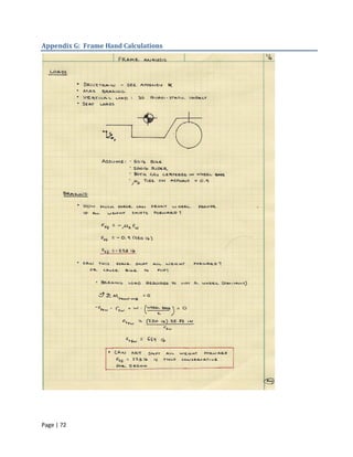
![Appendix J : Frame Load Calculations
Load Locations:
1. Bottom bracket loads
2. Front jackshaft loads
3. Rear jackshaft loads
Variables Units Variables Units Variables Units
F 500 lbf θ1 14.8 deg L2 0.5 in
lc 6.5 in θ2 14.8 deg L3a 1 in
dg 7.6 in θ3 45.47 deg L3b 1.20 in
dp - in θ4 45.47 deg D1 1.75 in
dc1 2.55 in θ5 10.56 deg D2 1 in
dc2 3.18 in L1 1 in D3 1 in
Tension Vertical Shaft Horizontal Shaft
Location [lb] Loads [lb] Loads [lb]
1 855 -219 -827
2 855 -391 227
3 684 735 -73
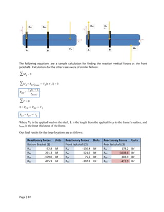
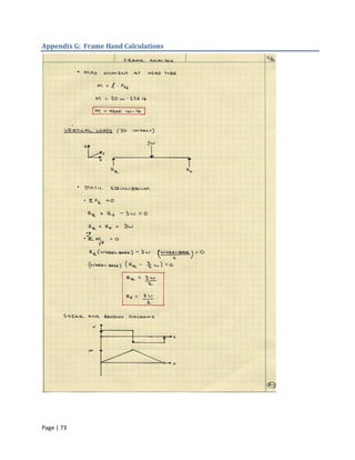
After the forces from the chain were calculated, each loading location was analyzed to find the reactionary
forces on the frame. The loading was analyzed in the z-x coordinates, or vertical force, and the y-x
coordinates, or horizontal force. A sample free body diagram is shown below with reaction forces acting
on the right (drive) and left (non-drive) sides.
Page | 81](https://image.slidesharecdn.com/hpvseniorprojectreport2009-1250197658912-phpapp02/85/HPV-Senior-Project-Report-2009-82-320.jpg)