This document summarizes the specifications and characteristics of HHE series low ohm power resistors from HTR-India. Key details include:
- Power ratings from 4W to 10W depending on resistance value and operating temperature
- Applications in power tools, automotive equipment, frequency converters, and power modules
- Resistance range from 0.003 ohms to 2 ohms with tolerances from ±0.25% to ±5%
- Operating temperature range of -55°C to +170°C with derating curves provided
- Electrical and environmental testing qualifications including temperature cycling, humidity, vibration, and power cycling
![PHYSICAL CONFIGURATION LOW OHM
POWER
RESISTORS
HHESERIES
Size 3820
2/5
e : info@htr-india.com
www.htr-india.com
APPLICATIONS
• Power tools due to nature of physical construction.
• High current applications for the automotive sector.
• Frequency convertors.
• Power modules.
FEATURES
• 5W constant power possible in R0003.
• Constant current carrying capability upto 120amp (R0003).
• Sturdy copper connectors.
• Excellent long term stability.
DIMENSIONAL TABLE
ELECTRICAL AND ENVIRONMENTAL CHARACTERISTICS
PARAMETER / PERFORMANCE TEST & TEST METHOD PERFORMANCE REQUIREMENTS
Power Rating For FeCrAl - Full power dissipation at 70° C and linearly derated to
zero at +170° C.
For Manganin (< 0.5% Improved Stability) -
Full power dissipation at 105° C & linearly derated to zero at +140° C.
For Manganin (< 1% Stability) - Full power dissipation at 135° C and
linearly derated to zero at +170° C.
Inductance < 3nH
Temperature Range - 55° C to +170° C (Suitably derated as per derating curve provided)
Voltage Rating / LimitingVoltage / Max.WorkingVoltage P x R
(Subject to max.TerminalTemperature of 135° C)
LowTemperature Storage and Operation [-65° C for 250 h] ∆R ± 0.2% - Average
Temperature Coefficient of Resistance From 100 ppm / K (Depending on Resistance Value)
(AmbientTemperature Range 20° C - 60° C)
Temperature Cycling -2000 cycles (-55° C to 150° C) ∆R ± 0.5% - Average
LifeTest / Operational Life - 2000 h rated power with ∆R ± 1% - Average
Temperature limitation onTerminal kept at 135° C
Moisture Resistance [MIL-STD-202 method106] ∆R ± 0.1% -Typical
Mechanical Shock [100 g. 6 ms half sine] ∆R ± 0.2% -Typical
Vibration, High Frequency [20 g. 10-2000 Hz] ∆R ± 0.2% -Typical
Bias Humidity [+85° C, 85% RH, 1000h] ∆R ± 0.5% -Typical
Resistance to Soldering Heat 260°C for 10 sec / 8h steam aging
HighTemperature Exposure – 2000h / 170°C ΔR ± 1% - Average (In covered condition)
Rev Date : 26/08/2020
Sr HTR RESISTANCE Tolerance WATTAGE WATTAGE D1 (mm) D2 (mm) INTERNAL HEAT TCR Typical WT.
No. TYPE Value AT 100°C AT 70°C ± 0.10 ± 0.10 RESISTANCE (Rthi) (ppm) PER PC. (gms)
1 HHE5W R0003 R0003 ± 0.25, ± 0.5, ± 1, ± 2, ± 3, ± 5% 5W 10W 1.42 1.42 4°K/W <100 1.10
2 HHE5W R0005 R0005 ± 0.25, ± 0.5, ± 1, ± 2, ± 3, ± 5% 5W 9W 0.86 0.86 7°K/W < 100 0.65
3 HHE5W R001 R001 ± 0.25, ± 0.5, ± 1, ± 2, ± 3, ± 5% 5W 8W 1.36 1.36 8°K/W < 100 0.89
4 HHE4W R002 R002 ± 0.25, ± 0.5, ± 1, ± 2, ± 3, ± 5% 4W 6W 0.68 0.68 15°K/W < 100 0.44](https://image.slidesharecdn.com/hhe-200909082458/85/HHE-2-320.jpg)
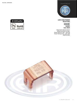
![LOW OHM
POWER
RESISTORS
HHESERIES
Size 3820
4/5
e : info@htr-india.com
www.htr-india.com
Rev Date : 26/08/2020
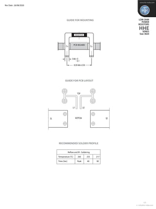
TYPICAL POWER DERATING CURVE FOR
RESISTOR WHEn full power is at 105oC & 135oC
TYPICAL POWER DERATING CURVE FOR
RESISTOR WHEn full power is at 70oC
In case the Design Engineer requires a specific graph of a particular component it can be supplied on request.
TYPICAL TEMPERATURE DEPENDANCE OF HHE SERIES
MAXIMUM PULSE ENERGY WITH RESPECT TO PULSE POWER FOR PERMANANT OPERATION
1
0.75
0,5
0.25
0
0 20 40 60 80 100 120 140 160 180
1.25
Terminal Temperature [°C]
P/P100 °C
Stability <1.0%
Improved Stability <0.5%
1
0.75
0,5
0.25
0
0 20 40 60 8070 100 120 140 160 180
1.25
Terminal Temperature [°C]
P/P 70 °C
-40
-1.0
0.0
0.2
0.4
0.6
0.8
1.0
-0.2
-0.4
-0.6
-0.8
-20 0 20 40 60 80 100 120
Temperature [°C]
dR/R100 [%]
Limiting Curve
Typical temperature dependence of a resistor made with Mangnin
140
In this graph the max. & min. curve are shown as and for all resistance values, the area between the max. & min. curve is applicable.
In case the Design Engineer requires a specific graph of a particular component it can be supplied on request.
10000
1000
100
10
1
1
10000 1000
10 100
0.0001
0.001
0.01
0.1
1
10
100
0.1
0.1
0.01
0.01
Pulse width [sec]
Pulseenergy[J]
Power[W]](https://image.slidesharecdn.com/hhe-200909082458/85/HHE-4-320.jpg)