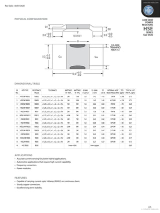
This document provides information on low ohm power resistors in the HSE series. It includes specifications for 11 resistor models with resistance values ranging from R0002 to R005 and power ratings from 2W to 12W. Key features highlighted are the ability to carry currents up to 160A, sturdy copper connectors, and excellent long-term stability. Dimensions, tolerances, and other electrical and mechanical characteristics are provided in tables.
![Recommended Pcb - Layout
www.htr-india.com
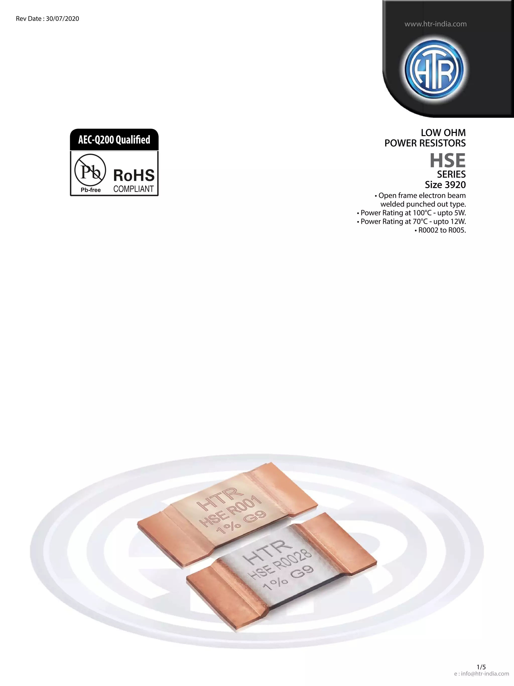
LOW OHM
POWER
RESISTORS
HSE
SERIES
Size 3920
RECOMMENDED SOLDER PROFILE
ELECTRICAL AND ENVIRONMENTAL CHARACTERISTICS
Reflow and IR soldering
Temperature (°C) 260 255 217
Time (Sec) Peak 40 90
Rev Date : 30/07/2020
2.70 2.70
5.60
6.20
Recommended PCB layout for high precision applications Recommended PCB layout for normal application
Sense Terminals
e : info@htr-india.com
3/5
PARAMETER / PERFORMANCE TEST & TEST METHOD PERFORMANCE REQUIREMENTS
Power Rating For FeCrAl - Full power dissipation at 70° C and linearly derated to
zero at +170° C.
For Manganin (< 0.5% Improved Stability) -
Full power dissipation at 100° C & linearly derated to zero at +140° C.
For Manganin (< 1% Stability) - Full power dissipation at 130° C and
linearly derated to zero at +170° C.
Inductance < 3nH
Temperature Range - 65° C to +170° C (Suitably derated as per derating curve provided)
Voltage Rating / LimitingVoltage / Max.WorkingVoltage
(Subject to max.TerminalTemperature of 130° C)
LowTemperature Storage and Operation [-65° C for 250 h] ∆R ± 0.1% - Average
Temperature Coefficient of Resistance From 50 ppm / K (Depending on Resistance Value)
(AmbientTemperature Range 20° C - 60° C)
Temperature Cycling -2000 cycles (-55° C to 150° C) ∆R ± 0.5% - Average
LifeTest / Operational Life - 2000 h rated power with ∆R ± 1% - Average
Temperature limitation onTerminal kept at 130° C
Moisture Resistance [MIL-STD-202 method106] ∆R ± 0.1% - Average
Mechanical Shock [100 g. 6 ms half sine] ∆R ± 0.2% -Typical
Vibration, High Frequency [20 g. 10-2000 Hz] ∆R ± 0.2% -Typical
Bias Humidity [+85° C, 85% RH, 1000h] ∆R ± 0.5% -Typical
Resistance to Soldering Heat 260°C for 10 sec / 8h steam aging
HighTemperature Exposure – 2000h / 170°C ΔR ± 1% - Average (In covered condition)
P x R](https://image.slidesharecdn.com/hse-size3920-300720-210710100807/85/Hse-size-3920-300720-3-320.jpg)
![TYPICAL POWER DERATING CURVE FOR
RESISTOR WHEn full power is at 100oC & 130oC
TYPICAL POWER DERATING CURVE FOR
RESISTOR WHEn full power is at 70oC
1
0.75
0,5
0.25
0
0 20 40 60 80
70 100 120 140 160 180
1.25
Terminal Temperature [°C]
P/P 70 °C
In this graph the max. & min. curve are shown as and for all resistance values, the area between the max. & min. curve is applicable.
In case the Design Engineer requires a specific graph of a particular component it can be supplied on request.
Typical Temperature dependance of the electrical resistance
MAXIMUM PULSE ENERGY WITH RESPECT TO PULSE POWER FOR PERMANANT OPERATION
10000
1000
100
10
1
1
10000 1000
10 100
0.0001
0.001
0.01
0.1
1
10
100
0.1
0.1
0.01
0.01
Pulse width [sec]
Pulse
energy
[J]
Power
[W]
www.htr-india.com
LOW OHM
POWER
RESISTORS
HSE
SERIES
Size 3920
-40
-1
1
0.8
0.6
0.4
0.2
0
-0.2
-0.4
-0.6
-0.8
-20 0 20 40 60 80 100 120
Temperature [°C]
dR/R20 [%]
Limiting Curve
Typical temperature dependence of a rresistor made with manganin
140 -40
-1.0
-0.5
0.0
0.5
1.0
-20 0 20 40 60 80 100 120
Temperature [°C]
dR/R20 [%]
Limiting Curve
Typical temperature dependence of aresistor made with FeCrAl
140 160
In case the Design Engineer requires a specific graph of a particular component it can be supplied on request.
•••
1
0.75
0.5
0.25
0
0 20 40 60 80 100 120 140 160 180
1.25
Terminal Temperature [°C]
P/P100 °C
Stability <1.0%
Improved Stability <0.5%
Rev Date : 30/07/2020
e : info@htr-india.com
4/5](https://image.slidesharecdn.com/hse-size3920-300720-210710100807/85/Hse-size-3920-300720-4-320.jpg)