This document provides information about low ohm power resistors made by HTR India. It includes specifications for resistance values and tolerances, power ratings at different temperatures, dimensions, applications like current sensors and power modules, features like maximum current capacity and solder temperature resistance, recommended layout and solder profile, electrical and environmental test results, derating curves, ordering information examples, and packaging in bulk boxes or tape and reel. The resistors are open frame welded designs for applications requiring high current capacity.

![RECOMMENDED PCB - LAYOUT
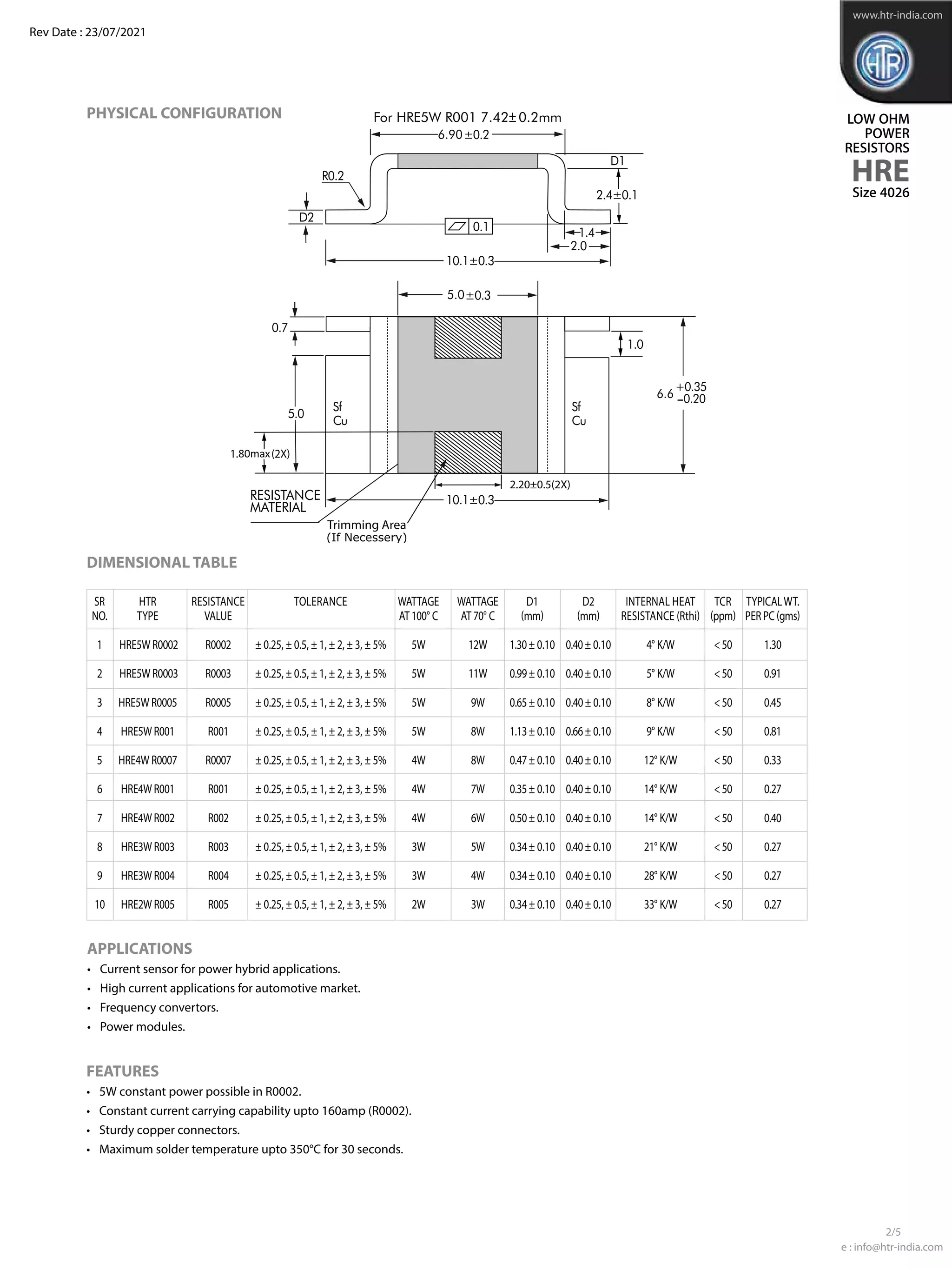
LOW OHM
POWER
RESISTORS
HRE
www.htr-india.com
Rev Date : 23/07/2021
Size 4026
RECOMMENDED SOLDER PROFILE
Reflow, IR - Soldering
Temperature (°C) 260 255 217
Time (Sec) Peak 40 90
e : info@htr-india.com
3/5
ELECTRICAL AND ENVIRONMENTAL CHARACTERISTICS
PARAMETER / PERFORMANCE TEST & TEST METHOD PERFORMANCE REQUIREMENTS
Power Rating For FeCrAl - Full power dissipation at 70° C and linearly derated to
zero at +170° C.
For Manganin (< 0.5% Improved Stability) -
Full power dissipation at 100° C & linearly derated to zero at +140° C.
For Manganin (< 1% Stability) - Full power dissipation at 130° C and
linearly derated to zero at +170° C.
Inductance < 3nH
Temperature Range - 65° C to +170° C (Suitably derated as per derating curve provided)
Voltage Rating / LimitingVoltage / Max.WorkingVoltage
(Subject to max.TerminalTemperature of 130° C)
LowTemperature Storage and Operation [-65° C for 250 h] ∆R ± 0.1% - Average
Temperature Coefficient of Resistance <50 ppm / K (Depending on Resistance Value)
(AmbientTemperature Range 20° C - 60° C)
Temperature Cycling -2000 cycles (-55° C to 150° C) ∆R ± 0.5% - Average
LifeTest / Operational Life - 2000 h rated power with ∆R ± 1% - Average
Temperature limitation onTerminal kept at 130° C
Moisture Resistance [MIL-STD-202 method106] ∆R ± 0.1% - Average
Mechanical Shock [100 g. 6 ms half sine] ∆R ± 0.2% -Typical
Vibration, High Frequency [20 g. 10-2000 Hz] ∆R ± 0.2% -Typical
Bias Humidity [+85° C, 85% RH, 1000h] ∆R ± 0.5% -Typical
Resistance to Soldering Heat 260°C for 10 sec / 8h steam aging
HighTemperature Exposure – 2000h / 170°C ΔR ± 1% - Average (In covered condition)
P x R](https://image.slidesharecdn.com/hre-210805095602/75/Hre-3-2048.jpg)
![LOW OHM
POWER
RESISTORS
HRE
e : info@htr-india.com
www.htr-india.com
Rev Date : 23/07/2021
Size 4026
4/5
TYPICAL POWER DERATING CURVE FOR
RESISTOR WHEn full power is at 100oC & 130oC
TYPICAL POWER DERATING CURVE FOR
RESISTOR WHEn full power is at 70oC
In case the Design Engineer requires a specific graph of a particular component it can be supplied on request.
TYPICAL TEMPERATURE DEPENDANCE electrical resistance
MAXIMUM PULSE ENERGY WITH RESPECT TO PULSE POWER FOR PERMANANT OPERATION
In this graph the max. & min. curve are shown as and for all resistance values, the area between the max. & min. curve is applicable.
In case the Design Engineer requires a specific graph of a particular component it can be supplied on request.
1
0.75
0,5
0.25
0
0 20 40 60 80 100 120 140 160 180
1.25
Terminal Temperature [°C]
P(W)/P
Stability <1.0% (in covered condition)
Stability <0.5%
Nom
Stability <1.0% (in covered condition)
1
0.75
0,5
0.25
0
0 20 40 60 80
70 100 120 140 160 180
1.25
Terminal Temperature [°C]
P(W)/PNom
0.8
0.6
0.4
-0.2
0
-0.2
-0.4
-0.6
-0.8
1
-40 -20 0 20 40 60 80 100 120 140
Temperature [°C]
dR/R20 [%]
Typical temperature dependence of a resistor made with Mangnin
Limiting Curve
-1
1.0
0.5
0.0
-0.5
-1.0
-40 -20 0 20 40 60 80 100 120 140 160
Temperature [°C]
dR/R20 [%]
Typical temperature dependence of a resistor made with FeCrAl
Limiting Curve
10000
1000
100
10
1
1
10000 1000
10 100
0.0001
0.001
0.01
0.1
1
10
100
0.1
0.1
0.01
0.01
Pulse width [sec]
Pulse
energy
[J]
Power
[W]](https://image.slidesharecdn.com/hre-210805095602/75/Hre-4-2048.jpg)


![Coded Agents – with UiPath SDK + LangGraph [Virtual Hands-on Workshop]](https://cdn.slidesharecdn.com/ss_thumbnails/codedagentsdeck-251215155422-5497c599-thumbnail.jpg?width=640&height=640&fit=bounds)


![Vibe Coding vs. Spec-Driven Development [Free Meetup]](https://cdn.slidesharecdn.com/ss_thumbnails/vibecodingvsspecdrivendevelopment-251209105622-43f455e7-thumbnail.jpg?width=640&height=640&fit=bounds)


