Download to read offline


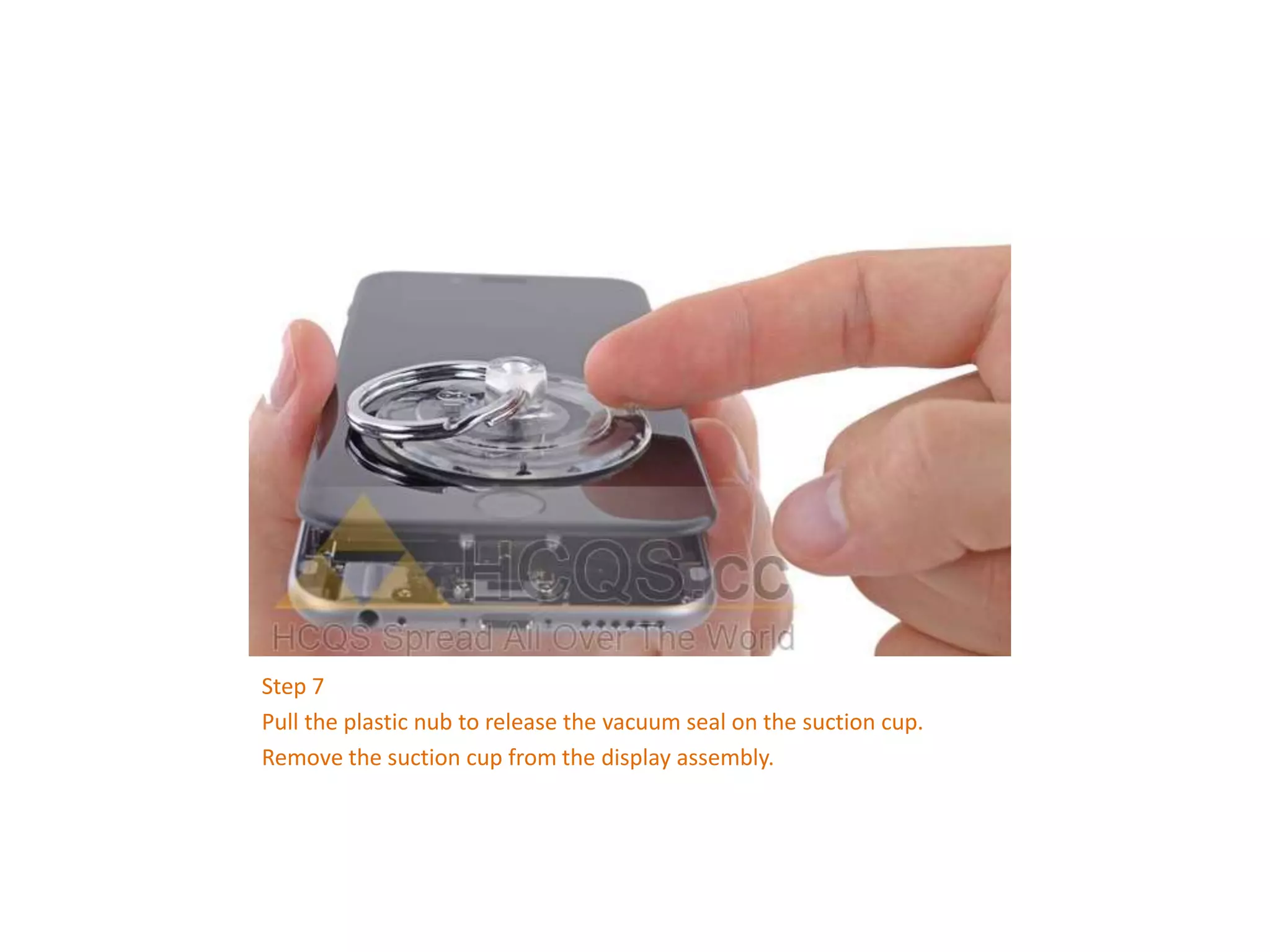

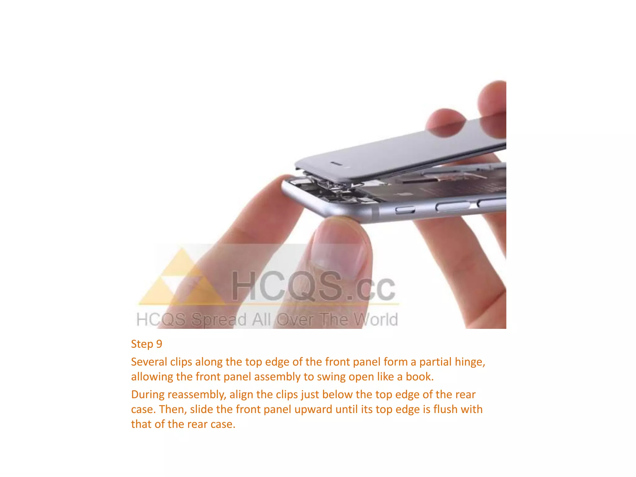


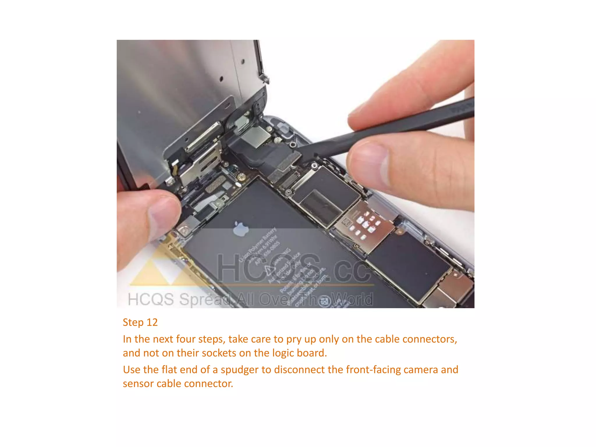
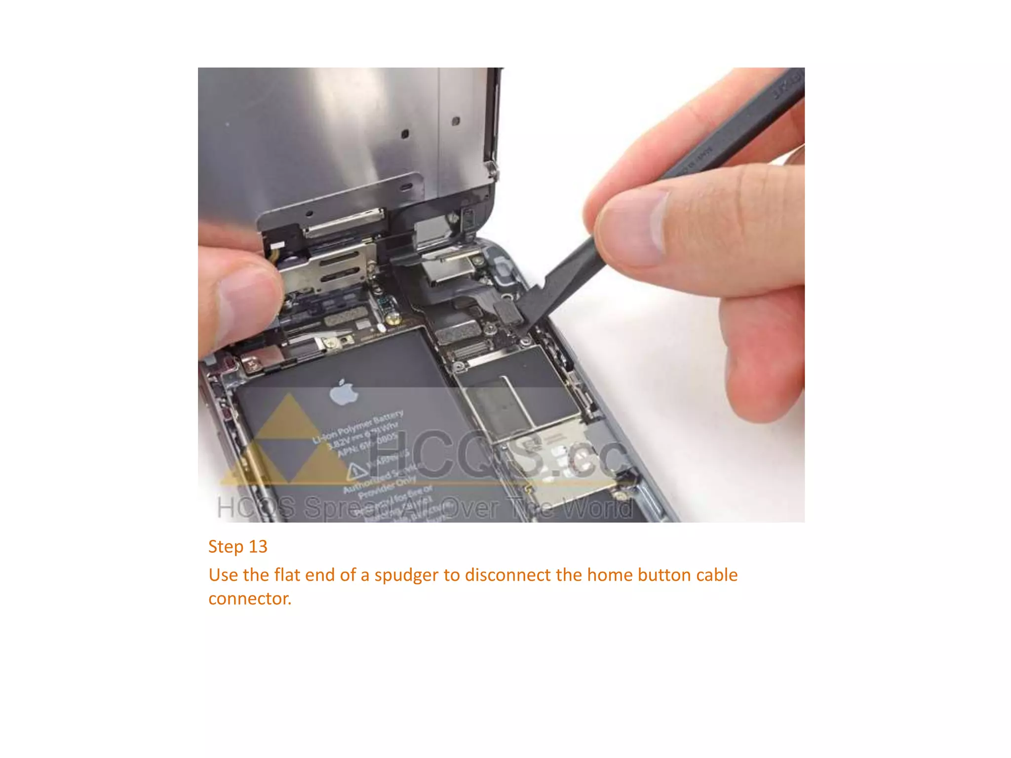


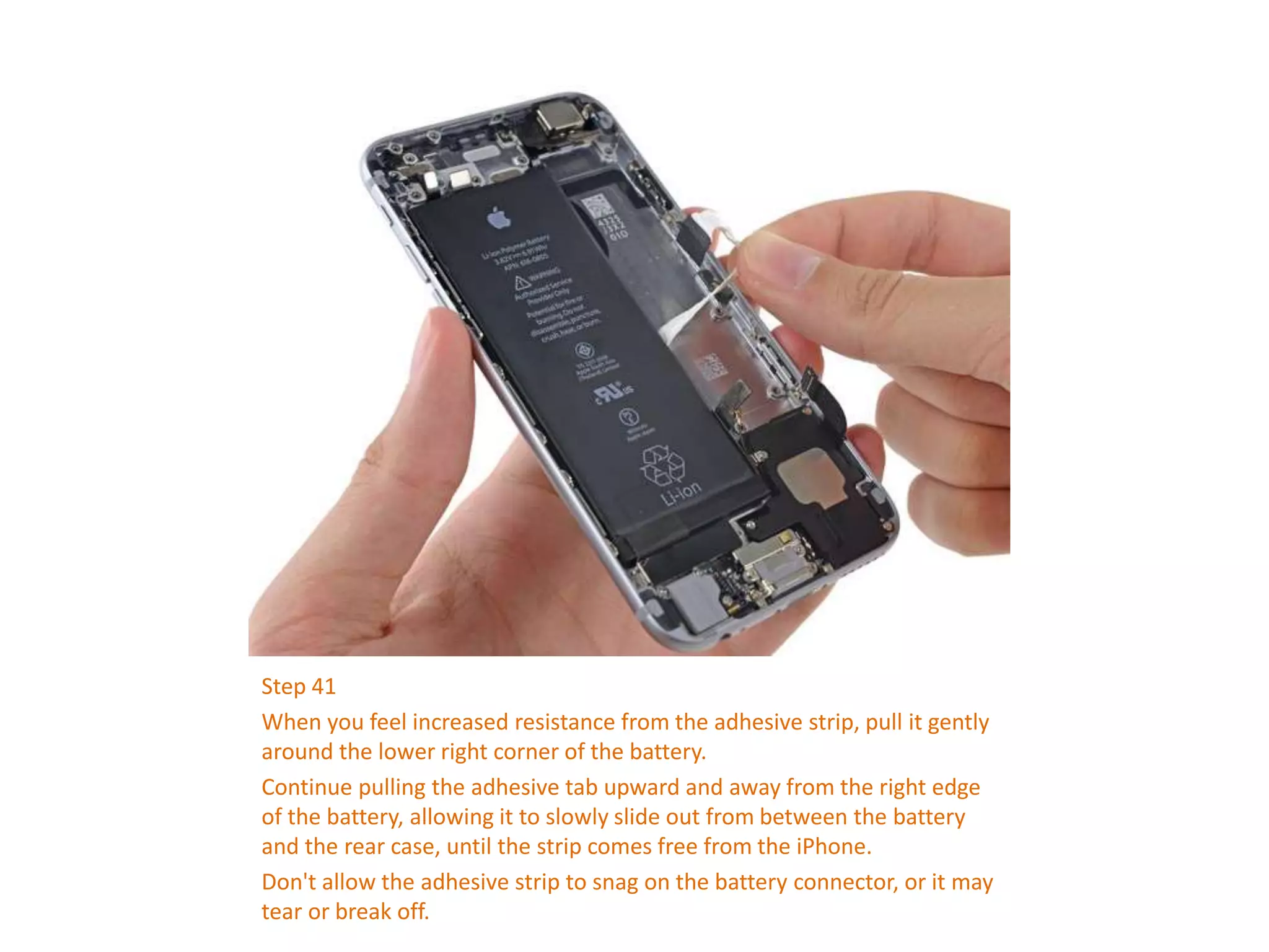
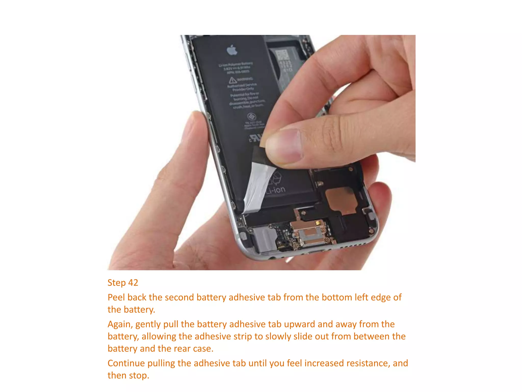
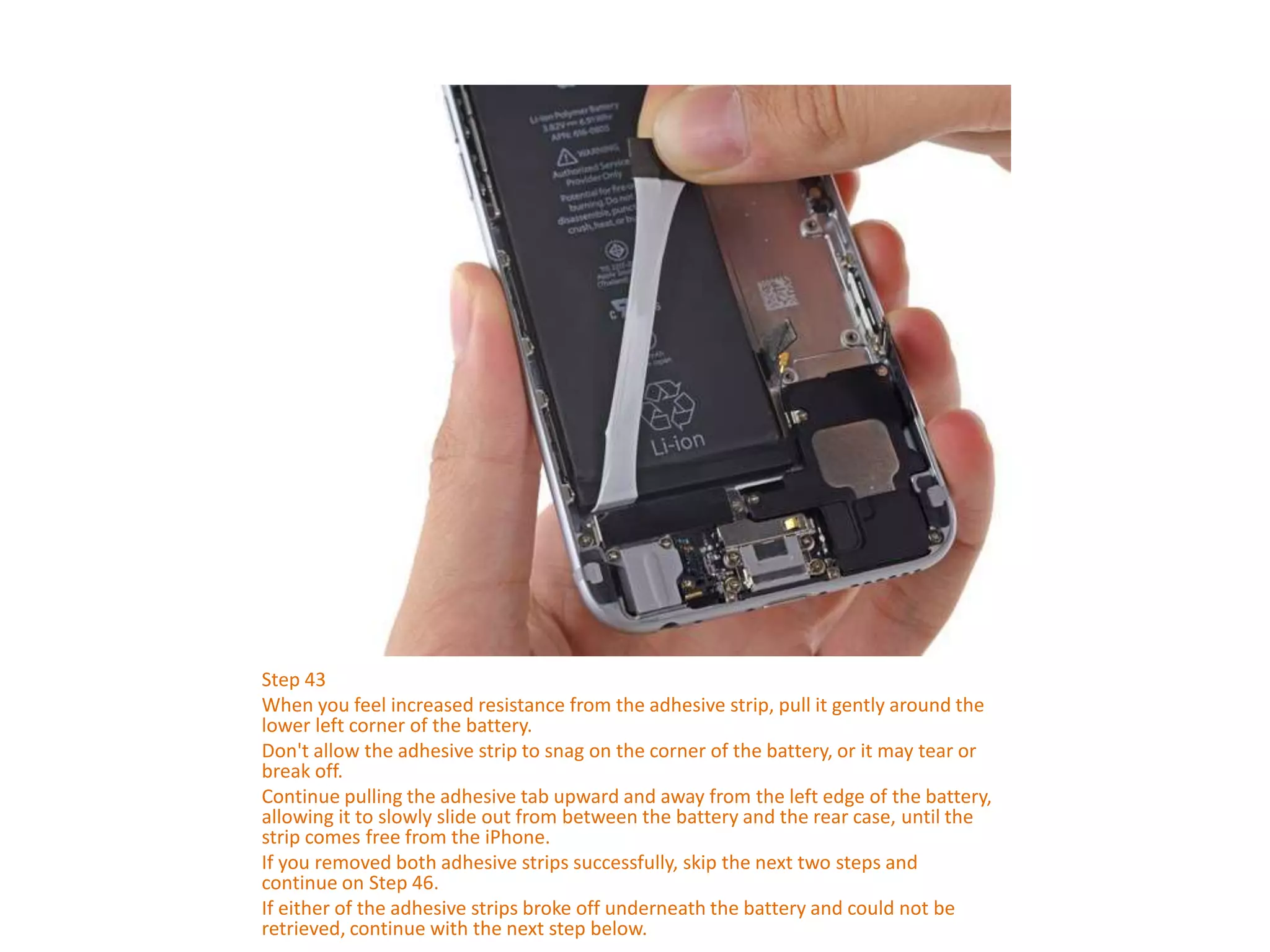
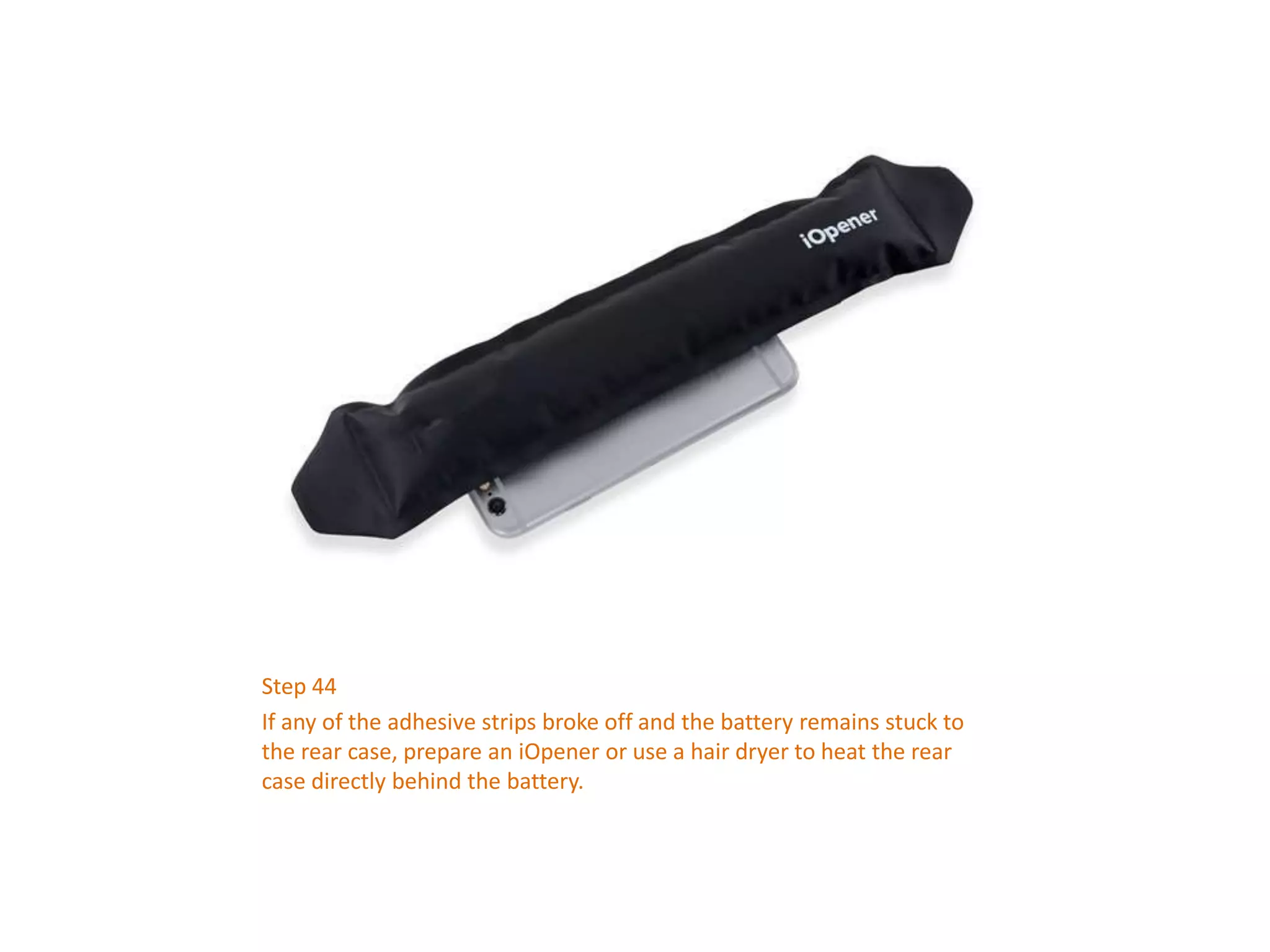
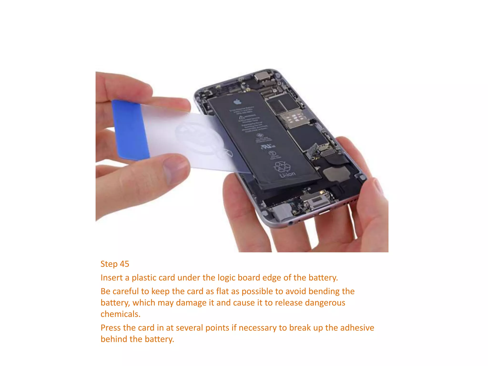
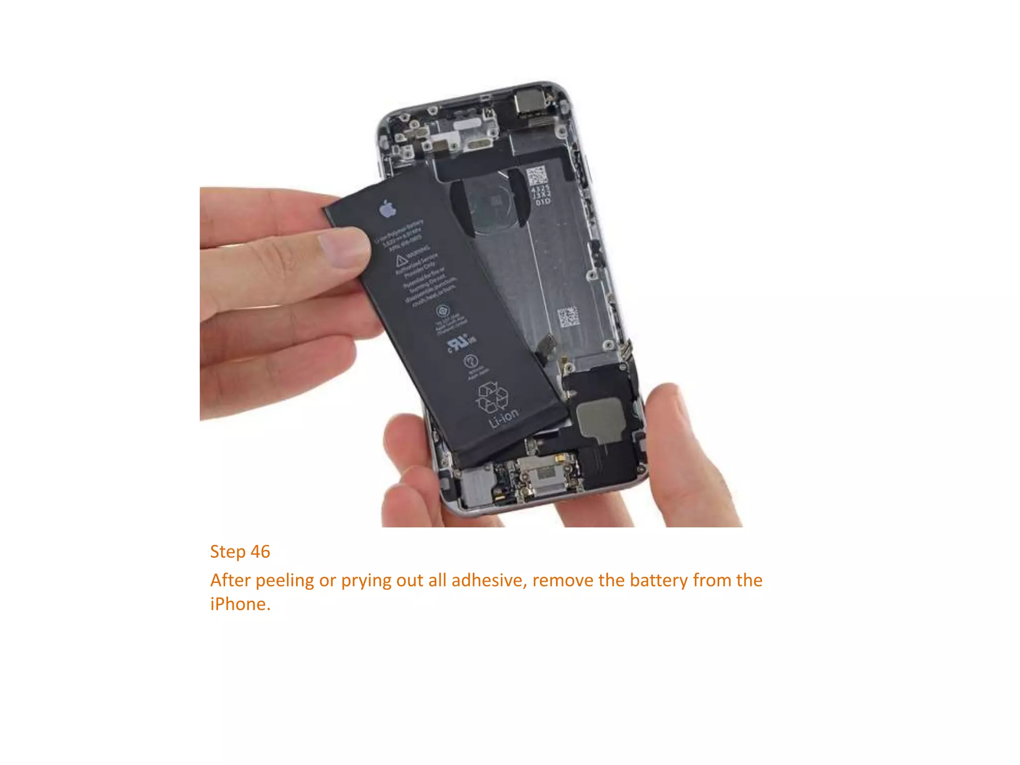


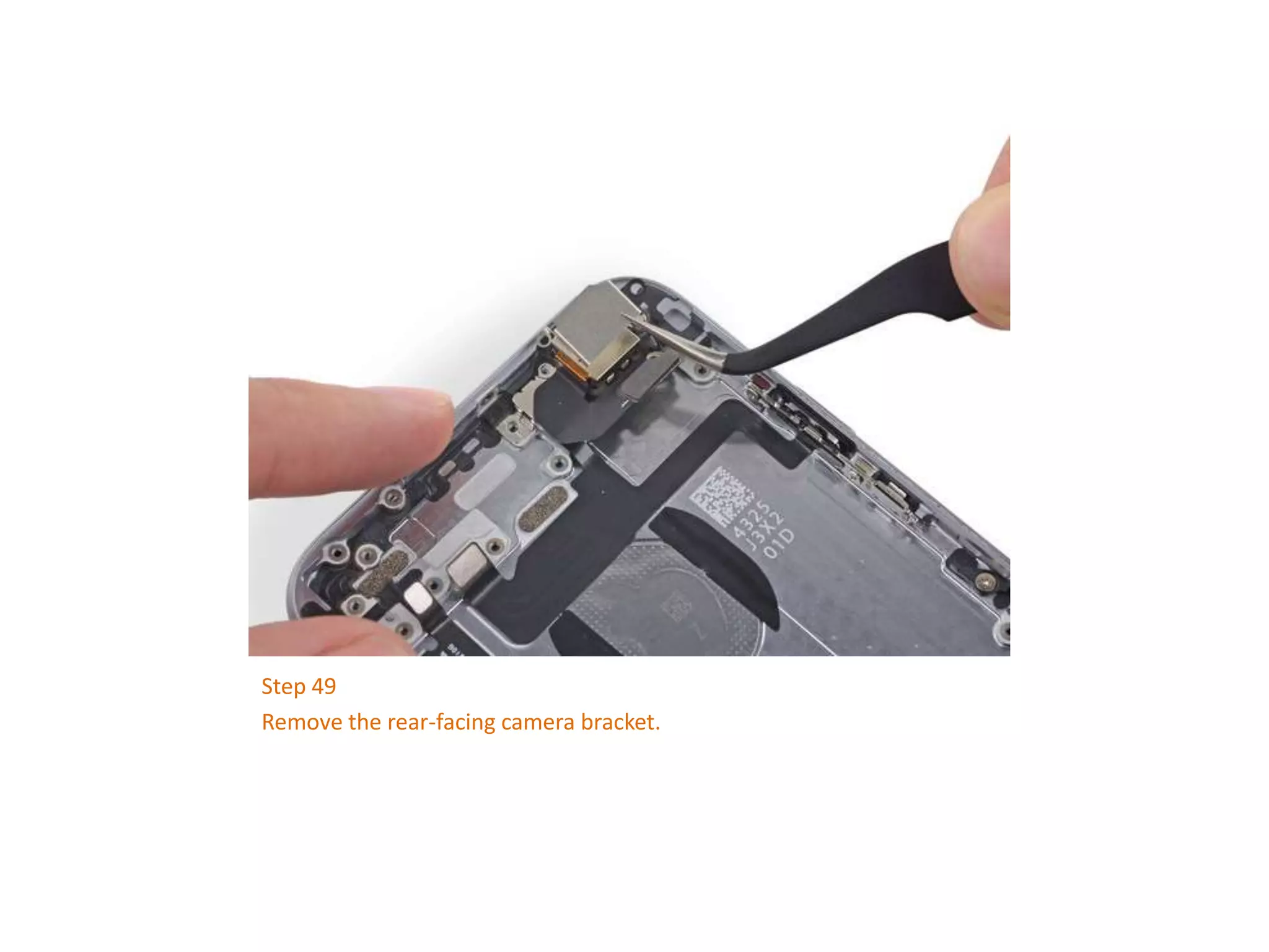
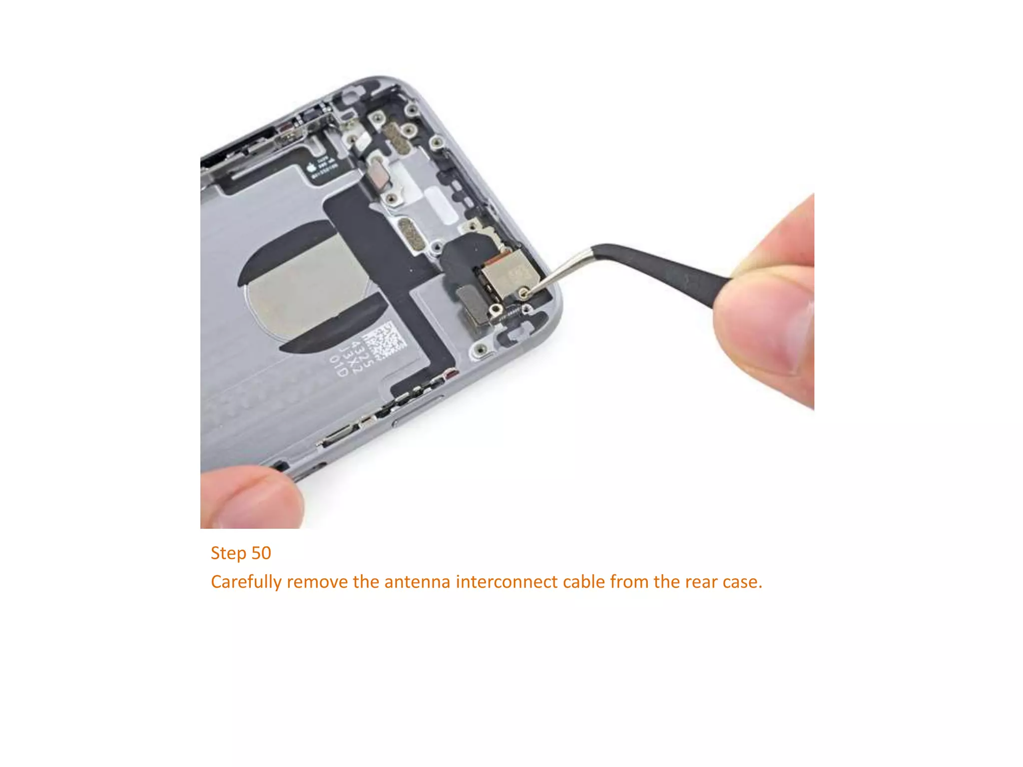


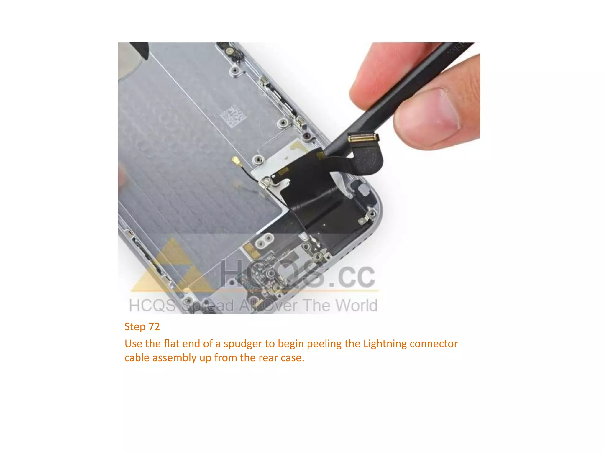


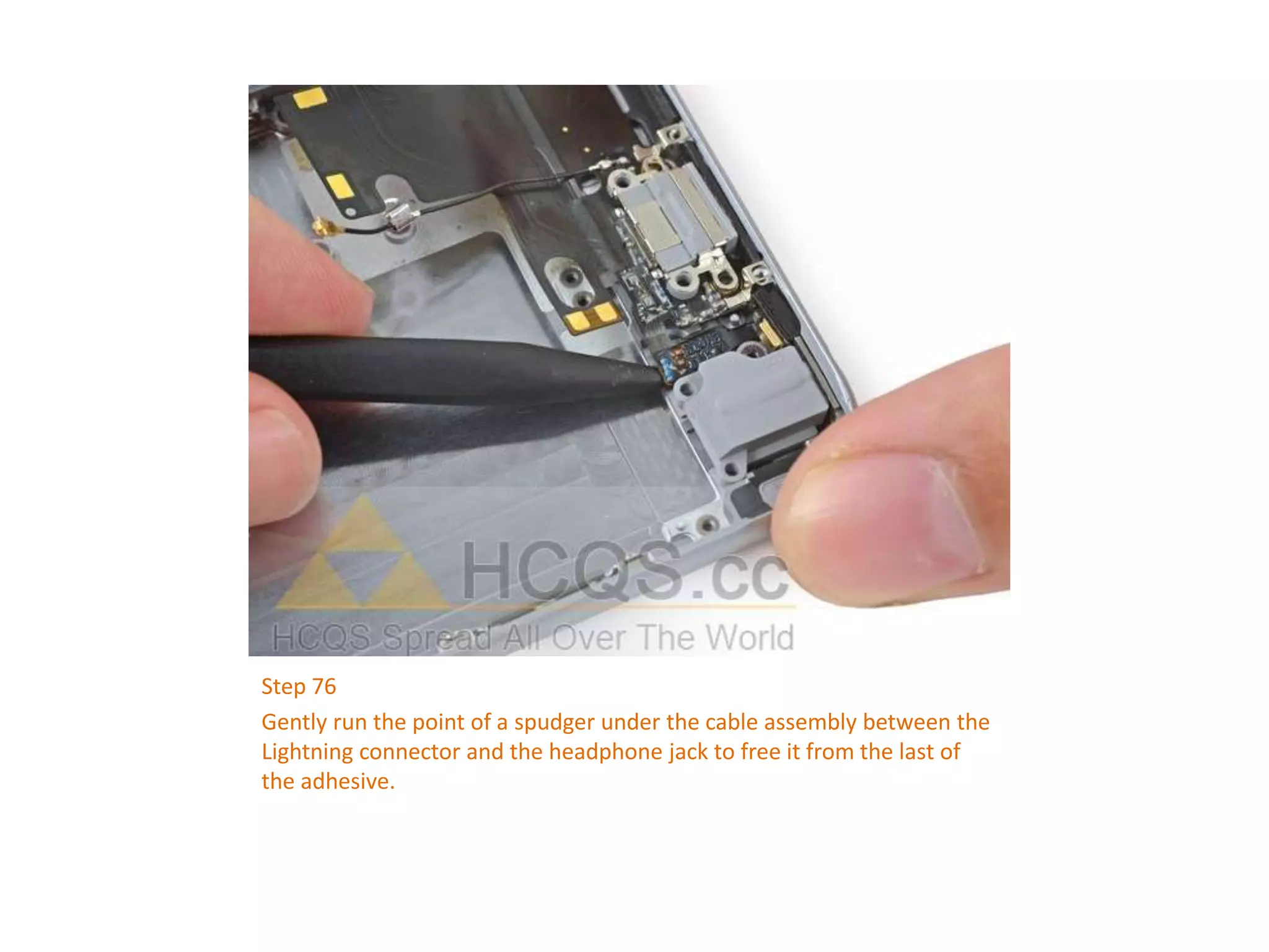


This document provides a detailed step-by-step guide for replacing the rear case of an iPhone 6, including necessary tools, disassembly instructions, and care tips. It outlines the process from powering off the device to removing internal components and the battery, emphasizing caution to avoid damaging connectors and components. The guide also includes reassembly instructions to complete the repair successfully.


