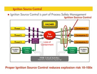
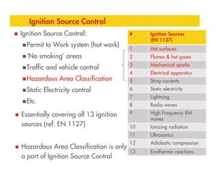
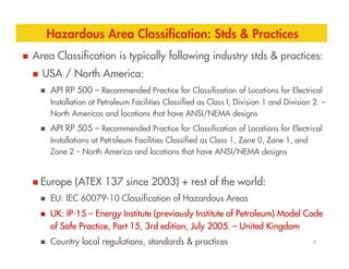
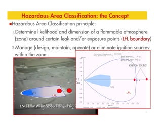
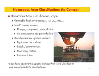
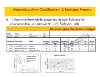
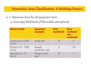
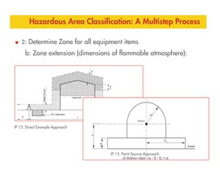
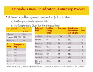
Hazardous Area Classification
Fundamentals & Cases
ATEX congres
Mei 2014, Dordrecht, Nederland
Erik van de Kuilen Shell Global Solutions Inc.
EX
Agenda
Fundamentals
Ignition Source Control
Standards & Practices
Area Classification: the Concept
Area Classification: a Multistep Process
Cases
2
Hot Surfaces
Management of Change – Gasgroup & Temperature class
Negligible Extent
Abnormal Operating Conditions - Temporary Zone 1
Management of Change – Release dispersion
Heat Exchanger Leakage
Ventilation
Q&A
Ignition Source Control…. or Not (?)
3
Hot
Surface
Ignition Source Control
Ignition Source Control is part of Process Safety Management
4
Loss of
Containment
Proper Ignition Source Control reduces explosion risk 10-100x
Ignition Source Control
Ignition Source Control:
Permit to Work system (hot work)
‘No smoking’ areas
Traffic and vehicle control
Hazardous Area Classification
# Ignition Sources
(EN 1127)
1 Hot surfaces
2 Flames & hot gases
3 Mechanical sparks
4 Electrical apparatus
5 Stray currents
5
Static Electricity control
Etc.
6 Static electricity
7 Lightning
8 Radio waves
9 High Frequency EM
waves
10 Ionizing radiation
11 Ultrasonics
12 Adiabatic compression
13 Exothermic reactions
Essentially covering all 13 ignition
sources (ref. EN 1127)
Hazardous Area Classification is only
a part of Ignition Source Control
Hazardous Area Classification: Stds & Practices
Area Classification is typically following industry stds & practices:
USA / North America:
API RP 500 – Recommended Practice for Classification of Locations for Electrical
Installation at Petroleum Facilities Classified as Class I, Division 1 and Division 2. –
North Americas and locations that have ANSI/NEMA designs
API RP 505 – Recommended Practice for Classification of Locations for Electrical
6
Installations at Petroleum Facilities Classified as Class 1, Zone 0, Zone 1, and
Zone 2 – North America and locations that have ANSI/NEMA designs
Europe (ATEX 137 since 2003) + rest of the world:
EU: IEC 60079-10 Classification of Hazardous Areas
UK: IP-15 – Energy Institute (previously Institute of Petroleum) Model Code
of Safe Practice, Part 15, 3rd edition, July 2005. – United Kingdom
Country local regulations, standards & practices
Hazardous Area Classification: the Concept
Hazardous Area Classification principle:
1.Determine likelihood and dimension of a flammable atmosphere
(zone) around certain leak and/or exposure points (LFL boundary)
2.Manage (design, maintain, operate) or eliminate ignition sources
within the zone
7
UFL
LFL
LFL
Hazardous Area Classification: the Concept
Hazardous Area Classification scope:
Flammable fluids (Hydrocarbons, H2, CO, NH3, …)
‘Small’ release sources:
Flanges, pump seals, vents, drains
No catastrophic equipment failure
(Semi)permanent ignition sources*:
8
(Semi)permanent ignition sources*:
Equipment hot surfaces
Roads / plant vehicles
Machinery motors
Instrumentation
*Open flame equipment is typically excluded from Area Classification
and located outside the classified area
Hazardous Area Classification: A Multistep Process
1: Determine flammability properties for each fluid and/or
equipment item (in particular LFL, UFL, flashpoint, AIT)
9
Hydrocarbon
Auto Ignition
Temperature
(AIT)
Hazardous Area Classification: A Multistep Process
2: Determine Zone for all equipment items
a: Zone type (likelihood of flammable atmosphere):
Release Grade Equipment
(example)
Zone
(ventilated)
Zone
(confined/
non-
10
b: Zone extension (dimensions of flammable atmosphere):
non-
ventilated)
Continuous (>1000
hr/yr)
Inside tank 0 0
Primary (10 - 1000
hr/yr)
Sample
connection, pits
1 1/0
Secondary (< 10
hr/yr)
Flange, pump
seal
2 1
Hazardous Area Classification: A Multistep Process
2: Determine Zone for all equipment items
b: Zone extension (dimensions of flammable atmosphere):
11
IP 15: Direct Example Approach
IP 15: Point Source Approach
Hazardous Area Classification: A Multistep Process
3: Determine fluid ignition parameters (ref. Literature)
a: the Gasgroup for the released fluid*
b: the Temperature Class for the released fluid
Released
fluid
Ignition
Energy
(mIE)
Gasgroup Auto Ignition
Temperature
(AIT) (deg C)
T
class
Methane 0.28 I /II A 525 T1
Fluid (typical) Gas
group
Alkanes II A
Ethylene, EO, CO II B
12
* Also ‘apparatus’ group or ‘explosion’ group; a parameter related to the sensitivity for ignition
Methane 0.28 I /II A 525 T1
Ethane 0.24 II A 510 T1
Propane 0.25 II A 460 T1
Hexane 0.24 II A 230 T3
Ethylene 0.07 II B 425 T2
Hydrogen 0.01 II C 560 T1
Benzene 0.2 II A 498 T1
Ethylene
Oxide
0.06 II B 429 T2
T
class
Temperature
(deg C)
1 450
2 300
3 200
4 135
5 100
6 85
Ethylene, EO, CO II B
Hydrogen II C
Hazardous Area Classification: A Multistep Process
4: Complete the Hazardous Area Classification Design Basis
and develop the drawings….
13
Hazardous Area Classification: A Multistep Process
14
///// Zone 2
Hazardous Area Classification: A Multistep Process
5: Implement and/or verify in the field:
(incl. selected explosion protection: ia, ib, d, e, n,...)
equipment nameplates
hot surfaces
roads & vehicles
6: Risk assess and/or modify any
Hazardous Area Classification: A Multistep Process
NAME PLATE:
Universal Supplies Ltd,
CE 0999
Trans type 100
II G
EEX ib IIC T4
Copyright of Shell Projects & Technology 16
October 2012
RESTRICTED
6: Risk assess and/or modify any
deviations from the required area
classification
(Ignition Hazard Analysis)
7: Document !
(Area Classification Design Basis,
Explosion Protection Document)
EEX ib IIC T4
40 C < Ta < 70 C
ACB 00 ATEX 9999
Apparatus parameters
Serial No. 991234
Hazardous Area Classification – Some Cases
1. Hot Surfaces
2. Management of Change – Gasgroup & Temperature class
3. Negligible Extent
4. Abnormal Operating Conditions - Temporary Zone 1 operation
5. Management of Change – Release dispersion
Copyright of Shell Projects & Technology 17
October 2012
RESTRICTED
5. Management of Change – Release dispersion
6. Heat Exchanger Leakage
7. Ventilation
Hot Surfaces
Hot equipment surfaces can be an ignition source, if the surface
temperature exceeds the Auto Ignition Temperature (AIT) of the
released fluid:
Operating temperature > Gasoline AIT
Copyright of Shell Projects & Technology 18
October 2012
RESTRICTED
Hot Surfaces
Risk Considerations (Ignition Hazard Analysis):
What is the actual Heating Medium line surface temperature? Is the line
insulated or could it be ? Is the insulation gas tight? Are there any flanges?
Will the Gasoline indeed reach the Heating Medium line and heat up to AIT?
Could any Gasoline leak points perhaps be eliminated or relocated?
Could the Heating Medium line be rerouted/shielded off?
API RP 2216-03:
Copyright of Shell Projects & Technology 19
October 2012
RESTRICTED
API RP 2216-03:
Ignition Risk of Hydrocarbon Liquids and Vapors by Hot Surfaces in Open Air:
“ignition of hydrocarbons by a hot surface should not be assumed unless the
surface temperature is approximately 360 °F (182°C) above the accepted
minimum ignition temperature of the hydrocarbon involved.”
Consider ignition due to hot surface*:
Zone 0 & Zone 1: fluid AIT
Zone 2: fluid AIT + 180 °C.
* EN1127 indicates 80% of AIT for Zone 0 and 1 and AIT for Zone 2
Hot Surfaces
A new insulated Steam line (Operating Temperature > 300 C) into
an existing pipe track (conservatively) classified as Zone 1 with
fluids AITs < 250 C: New steam line
Existing pipe track
Zone 1
Copyright of Shell Projects & Technology 20
October 2012
RESTRICTED
Alternative: installing a new 2 km pipe rack
Risk Considerations (Ignition Hazard Analysis):
API 2216 not applicable for Zone 1 (only for well ventilated systems)
What is the Steam line surface temperature? What about flanges?
Where are the Hydrocarbon leak sources? Close to Steam line hot points?
Could the Steam line be shielded/segregated from the Hydrocarbon lines?
Management of Change – Gasgroup and T Class
Existing / Replaced IIA-T3
Equipment / zone
(max surface temp. 200 ̊C)
New IIA-T2 equipment / zone
(max surface temp. 300 ̊C)
Existing IIA-T3 and
IIC-T3 Equipment /
T2 equipment
Installing new equipment in
existing facility New IIC-T2 equipment / zone
(max surface temp. 300 ̊C)
New IIA-T2 equipment / zone
(max surface temp. 300 ̊C)
IIC-T3 Equipment /
zone (max surface
temp. 200 ̊C)
in T3 zone
IIA equipment in
IIC zone
Zone with Negligible Extent (NE)
During facility decommissioning
residual Hydrocarbons at low/no
pressure may retain inside and
dictate need for Area
Classification .
EN 60079-10-1 has introduced
the concept of Zone with
Negligible Extend (NE).
Zone 2 NE is accepted by the UK
Health and Safety Executive
(HSE) and does not require
control of ignition sources within
it.
Approach is being considered for
de-commissioning of platforms in
North Sea: Normal outside
conditions
Good High
Ventilation
required
Abnormal Operating Conditions (Drilling WHCP)
Platform Well Head Control Panel (WHCP)
cabinet (ca. 3 m3) is located in Zone 2 and
internally classified Zone 1. Zone 2 is
based on normal production.
During HAZOP it was found that for 3-6
months every 3-4 yrs, the platform is also
used to drill new wells.
This would require 3 m radius Zone 1
conditions extending over the WHCP.
Relocate/renew the cabinet for Zone 0 ?
Alternative? During Zone 1 operation:
Provide gas detection in/near the cabinet to indicate
increased gas concentration inside/outside the cabinet.
Install ventilation on the cabinet to maintain Zone 1 inside
Management of Change – Standards & Dispersion
New filter unit for FCC product
Distance from proposed location to
nearby road: 7.5 m
Zone radius/distance to road
according local standard: 15 m
This would require closure or
major rerouting of main access
road to Control Room and Unit….
Physical Effect Modeling:
Dispersion analysis shows max release
size 4.5 m from filter unit leak points
Supported by IP 15 Area Classification
point source method
IP 15 Point Source
Heat Exchanger Leakage (Cooling Water Return)
Leaking Heat Exchanger(s)
resulting in Hydrocarbon in open
Cooling Water Returns and may
be ignited
(CW Return not classified).
To reduce the risk:
To reduce the risk:
Zone 1/2 for the CW Return?
Install gas / Hydrocarbon
detection in CW Return +
Close off the road in case of gas
detection to prevent ignition by
passing vehicle
A similar case:
Heat Exchanger Leakage (Cooling Water Return)
CW tower fire
New designs would have closed CW return lines, classified
CW towers and Hydrocarbon vent in the return line:
Hydrocarbon Vent Line
CW Return Line
Ref. API 505
Ventilation (Winterizing)
During winter, some plants are ‘sheltered’ to prevent freezing
problems. This could impact the natural ventilation and the Zoning.
Ventilation (Winterizing)
Design and locate the screens such that (natural) ventilation is still
adequate:
50% LEL for secondary grade release
25% LEL for continuous & primary grade release
(ref. IEC 60079-10 ventilation calcs)
Winterizing
screens
If not adequate, then need to consider artificial ventilation and/or
gas detection
Zone 2 facility
Winterizing
screens
Open area
for
ventilation
Q & A
Hazad Area Classification fundamentals and codes

Hazad Area Classification fundamentals and codes

  • 1.
    Hazardous Area Classification Fundamentals& Cases ATEX congres Mei 2014, Dordrecht, Nederland Erik van de Kuilen Shell Global Solutions Inc. EX
  • 2.
    Agenda Fundamentals Ignition Source Control Standards& Practices Area Classification: the Concept Area Classification: a Multistep Process Cases 2 Hot Surfaces Management of Change – Gasgroup & Temperature class Negligible Extent Abnormal Operating Conditions - Temporary Zone 1 Management of Change – Release dispersion Heat Exchanger Leakage Ventilation Q&A
  • 3.
    Ignition Source Control….or Not (?) 3 Hot Surface
  • 4.
    Ignition Source Control IgnitionSource Control Ignition Source Control is part of Process Safety Management 4 Loss of Containment Proper Ignition Source Control reduces explosion risk 10-100x
  • 5.
    Ignition Source Control IgnitionSource Control: Permit to Work system (hot work) ‘No smoking’ areas Traffic and vehicle control Hazardous Area Classification # Ignition Sources (EN 1127) 1 Hot surfaces 2 Flames & hot gases 3 Mechanical sparks 4 Electrical apparatus 5 Stray currents 5 Static Electricity control Etc. 6 Static electricity 7 Lightning 8 Radio waves 9 High Frequency EM waves 10 Ionizing radiation 11 Ultrasonics 12 Adiabatic compression 13 Exothermic reactions Essentially covering all 13 ignition sources (ref. EN 1127) Hazardous Area Classification is only a part of Ignition Source Control
  • 6.
    Hazardous Area Classification:Stds & Practices Area Classification is typically following industry stds & practices: USA / North America: API RP 500 – Recommended Practice for Classification of Locations for Electrical Installation at Petroleum Facilities Classified as Class I, Division 1 and Division 2. – North Americas and locations that have ANSI/NEMA designs API RP 505 – Recommended Practice for Classification of Locations for Electrical 6 Installations at Petroleum Facilities Classified as Class 1, Zone 0, Zone 1, and Zone 2 – North America and locations that have ANSI/NEMA designs Europe (ATEX 137 since 2003) + rest of the world: EU: IEC 60079-10 Classification of Hazardous Areas UK: IP-15 – Energy Institute (previously Institute of Petroleum) Model Code of Safe Practice, Part 15, 3rd edition, July 2005. – United Kingdom Country local regulations, standards & practices
  • 7.
    Hazardous Area Classification:the Concept Hazardous Area Classification principle: 1.Determine likelihood and dimension of a flammable atmosphere (zone) around certain leak and/or exposure points (LFL boundary) 2.Manage (design, maintain, operate) or eliminate ignition sources within the zone 7 UFL LFL LFL
  • 8.
    Hazardous Area Classification:the Concept Hazardous Area Classification scope: Flammable fluids (Hydrocarbons, H2, CO, NH3, …) ‘Small’ release sources: Flanges, pump seals, vents, drains No catastrophic equipment failure (Semi)permanent ignition sources*: 8 (Semi)permanent ignition sources*: Equipment hot surfaces Roads / plant vehicles Machinery motors Instrumentation *Open flame equipment is typically excluded from Area Classification and located outside the classified area
  • 9.
    Hazardous Area Classification:A Multistep Process 1: Determine flammability properties for each fluid and/or equipment item (in particular LFL, UFL, flashpoint, AIT) 9 Hydrocarbon Auto Ignition Temperature (AIT)
  • 10.
    Hazardous Area Classification:A Multistep Process 2: Determine Zone for all equipment items a: Zone type (likelihood of flammable atmosphere): Release Grade Equipment (example) Zone (ventilated) Zone (confined/ non- 10 b: Zone extension (dimensions of flammable atmosphere): non- ventilated) Continuous (>1000 hr/yr) Inside tank 0 0 Primary (10 - 1000 hr/yr) Sample connection, pits 1 1/0 Secondary (< 10 hr/yr) Flange, pump seal 2 1
  • 11.
    Hazardous Area Classification:A Multistep Process 2: Determine Zone for all equipment items b: Zone extension (dimensions of flammable atmosphere): 11 IP 15: Direct Example Approach IP 15: Point Source Approach
  • 12.
    Hazardous Area Classification:A Multistep Process 3: Determine fluid ignition parameters (ref. Literature) a: the Gasgroup for the released fluid* b: the Temperature Class for the released fluid Released fluid Ignition Energy (mIE) Gasgroup Auto Ignition Temperature (AIT) (deg C) T class Methane 0.28 I /II A 525 T1 Fluid (typical) Gas group Alkanes II A Ethylene, EO, CO II B 12 * Also ‘apparatus’ group or ‘explosion’ group; a parameter related to the sensitivity for ignition Methane 0.28 I /II A 525 T1 Ethane 0.24 II A 510 T1 Propane 0.25 II A 460 T1 Hexane 0.24 II A 230 T3 Ethylene 0.07 II B 425 T2 Hydrogen 0.01 II C 560 T1 Benzene 0.2 II A 498 T1 Ethylene Oxide 0.06 II B 429 T2 T class Temperature (deg C) 1 450 2 300 3 200 4 135 5 100 6 85 Ethylene, EO, CO II B Hydrogen II C
  • 13.
    Hazardous Area Classification:A Multistep Process 4: Complete the Hazardous Area Classification Design Basis and develop the drawings…. 13
  • 14.
    Hazardous Area Classification:A Multistep Process 14 ///// Zone 2
  • 15.
    Hazardous Area Classification:A Multistep Process
  • 16.
    5: Implement and/orverify in the field: (incl. selected explosion protection: ia, ib, d, e, n,...) equipment nameplates hot surfaces roads & vehicles 6: Risk assess and/or modify any Hazardous Area Classification: A Multistep Process NAME PLATE: Universal Supplies Ltd, CE 0999 Trans type 100 II G EEX ib IIC T4 Copyright of Shell Projects & Technology 16 October 2012 RESTRICTED 6: Risk assess and/or modify any deviations from the required area classification (Ignition Hazard Analysis) 7: Document ! (Area Classification Design Basis, Explosion Protection Document) EEX ib IIC T4 40 C < Ta < 70 C ACB 00 ATEX 9999 Apparatus parameters Serial No. 991234
  • 17.
    Hazardous Area Classification– Some Cases 1. Hot Surfaces 2. Management of Change – Gasgroup & Temperature class 3. Negligible Extent 4. Abnormal Operating Conditions - Temporary Zone 1 operation 5. Management of Change – Release dispersion Copyright of Shell Projects & Technology 17 October 2012 RESTRICTED 5. Management of Change – Release dispersion 6. Heat Exchanger Leakage 7. Ventilation
  • 18.
    Hot Surfaces Hot equipmentsurfaces can be an ignition source, if the surface temperature exceeds the Auto Ignition Temperature (AIT) of the released fluid: Operating temperature > Gasoline AIT Copyright of Shell Projects & Technology 18 October 2012 RESTRICTED
  • 19.
    Hot Surfaces Risk Considerations(Ignition Hazard Analysis): What is the actual Heating Medium line surface temperature? Is the line insulated or could it be ? Is the insulation gas tight? Are there any flanges? Will the Gasoline indeed reach the Heating Medium line and heat up to AIT? Could any Gasoline leak points perhaps be eliminated or relocated? Could the Heating Medium line be rerouted/shielded off? API RP 2216-03: Copyright of Shell Projects & Technology 19 October 2012 RESTRICTED API RP 2216-03: Ignition Risk of Hydrocarbon Liquids and Vapors by Hot Surfaces in Open Air: “ignition of hydrocarbons by a hot surface should not be assumed unless the surface temperature is approximately 360 °F (182°C) above the accepted minimum ignition temperature of the hydrocarbon involved.” Consider ignition due to hot surface*: Zone 0 & Zone 1: fluid AIT Zone 2: fluid AIT + 180 °C. * EN1127 indicates 80% of AIT for Zone 0 and 1 and AIT for Zone 2
  • 20.
    Hot Surfaces A newinsulated Steam line (Operating Temperature > 300 C) into an existing pipe track (conservatively) classified as Zone 1 with fluids AITs < 250 C: New steam line Existing pipe track Zone 1 Copyright of Shell Projects & Technology 20 October 2012 RESTRICTED Alternative: installing a new 2 km pipe rack Risk Considerations (Ignition Hazard Analysis): API 2216 not applicable for Zone 1 (only for well ventilated systems) What is the Steam line surface temperature? What about flanges? Where are the Hydrocarbon leak sources? Close to Steam line hot points? Could the Steam line be shielded/segregated from the Hydrocarbon lines?
  • 21.
    Management of Change– Gasgroup and T Class Existing / Replaced IIA-T3 Equipment / zone (max surface temp. 200 ̊C) New IIA-T2 equipment / zone (max surface temp. 300 ̊C) Existing IIA-T3 and IIC-T3 Equipment / T2 equipment Installing new equipment in existing facility New IIC-T2 equipment / zone (max surface temp. 300 ̊C) New IIA-T2 equipment / zone (max surface temp. 300 ̊C) IIC-T3 Equipment / zone (max surface temp. 200 ̊C) in T3 zone IIA equipment in IIC zone
  • 22.
    Zone with NegligibleExtent (NE) During facility decommissioning residual Hydrocarbons at low/no pressure may retain inside and dictate need for Area Classification . EN 60079-10-1 has introduced the concept of Zone with Negligible Extend (NE). Negligible Extend (NE). Zone 2 NE is accepted by the UK Health and Safety Executive (HSE) and does not require control of ignition sources within it. Approach is being considered for de-commissioning of platforms in North Sea: Normal outside conditions Good High Ventilation required
  • 23.
    Abnormal Operating Conditions(Drilling WHCP) Platform Well Head Control Panel (WHCP) cabinet (ca. 3 m3) is located in Zone 2 and internally classified Zone 1. Zone 2 is based on normal production. During HAZOP it was found that for 3-6 months every 3-4 yrs, the platform is also used to drill new wells. used to drill new wells. This would require 3 m radius Zone 1 conditions extending over the WHCP. Relocate/renew the cabinet for Zone 0 ? Alternative? During Zone 1 operation: Provide gas detection in/near the cabinet to indicate increased gas concentration inside/outside the cabinet. Install ventilation on the cabinet to maintain Zone 1 inside
  • 24.
    Management of Change– Standards & Dispersion New filter unit for FCC product Distance from proposed location to nearby road: 7.5 m Zone radius/distance to road according local standard: 15 m This would require closure or major rerouting of main access major rerouting of main access road to Control Room and Unit…. Physical Effect Modeling: Dispersion analysis shows max release size 4.5 m from filter unit leak points Supported by IP 15 Area Classification point source method IP 15 Point Source
  • 25.
    Heat Exchanger Leakage(Cooling Water Return) Leaking Heat Exchanger(s) resulting in Hydrocarbon in open Cooling Water Returns and may be ignited (CW Return not classified). To reduce the risk: To reduce the risk: Zone 1/2 for the CW Return? Install gas / Hydrocarbon detection in CW Return + Close off the road in case of gas detection to prevent ignition by passing vehicle A similar case:
  • 26.
    Heat Exchanger Leakage(Cooling Water Return) CW tower fire New designs would have closed CW return lines, classified CW towers and Hydrocarbon vent in the return line: Hydrocarbon Vent Line CW Return Line Ref. API 505
  • 27.
    Ventilation (Winterizing) During winter,some plants are ‘sheltered’ to prevent freezing problems. This could impact the natural ventilation and the Zoning.
  • 28.
    Ventilation (Winterizing) Design andlocate the screens such that (natural) ventilation is still adequate: 50% LEL for secondary grade release 25% LEL for continuous & primary grade release (ref. IEC 60079-10 ventilation calcs) Winterizing screens If not adequate, then need to consider artificial ventilation and/or gas detection Zone 2 facility Winterizing screens Open area for ventilation
  • 29.