This document summarizes a study using Star-CCM+ software to model microfluidic flows. Single-phase flow in rectangular and circular microchannels was modeled and validated against analytical solutions. Droplet formation in a microfluidic T-junction and flow focusing device was also modeled using the volume of fluid method. High spurious currents were observed at fluid interfaces with coarse meshes. Adaptive mesh refinement was employed for the flow focusing device to minimize currents and sharpen interfaces, improving the model.
![1
application is the use of droplets as chemical reactors where the kinetics can be monitored and
controlled precisely. Droplets have also been used as templates for producing micro-particles
with specialized biological, chemical, and optical properties. Creation of mono-disperse
emulsions requires microfluidic channels for droplet formation as traditional methods produce
droplets of varying sizes [1].
However, many unexpected phenomena have been reported when dealing with micro-flows [2].
The limited available data show behavior that is either exactly same or significantly different
from the macroscopic behavior and theory. The reason for this anomaly has been attributed to
micro-effects, which become significant as the characteristic length scale decreases. Some of
these micro-effects include high lateral momentum diffusion, surface forces etc. Also, the
applicability of continuum hypothesis is questionable.
The present study investigates the ability of Star-CCM+ to model flows in Microchannels. Flows
for low Knudsen number have been studied to eliminate inapplicability of continuum hypothesis.
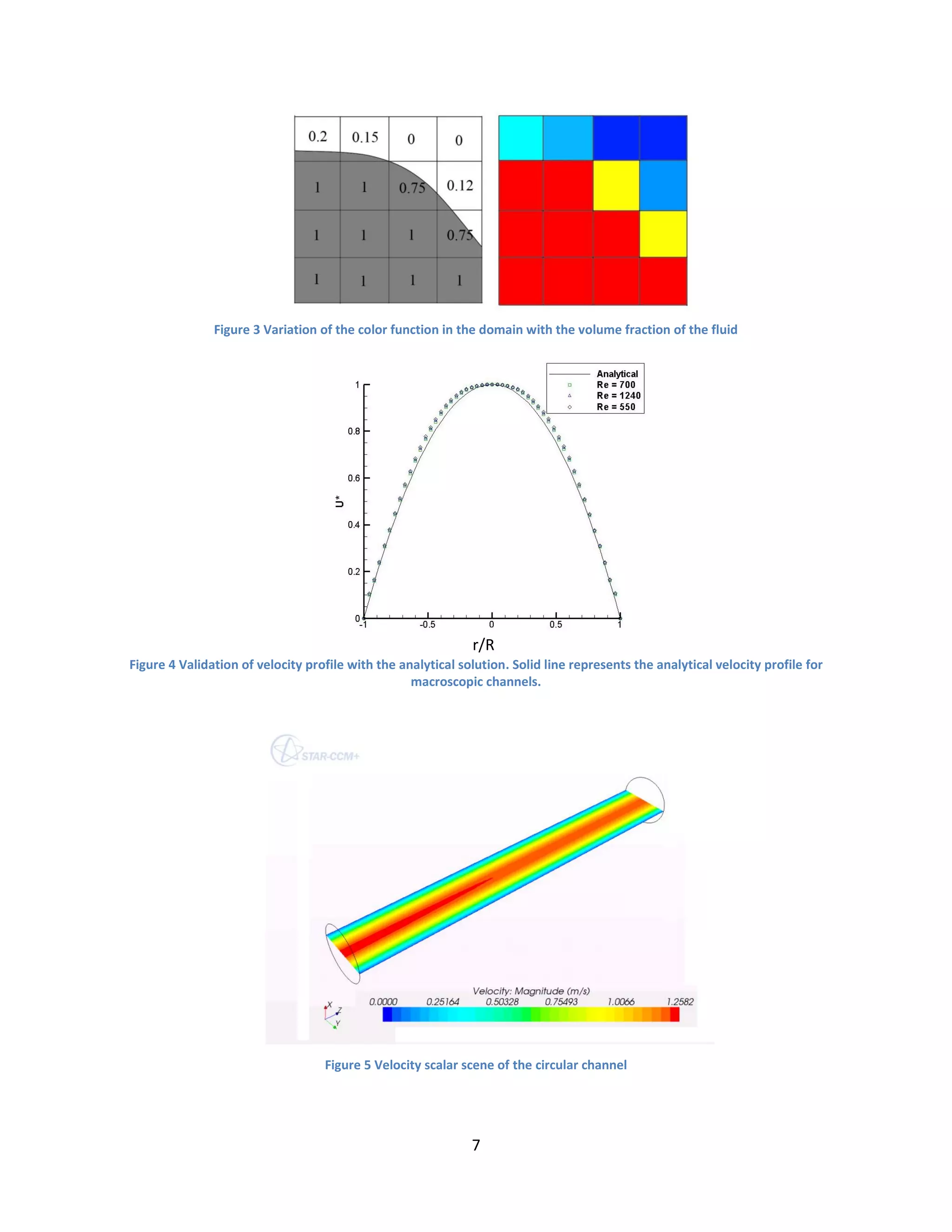
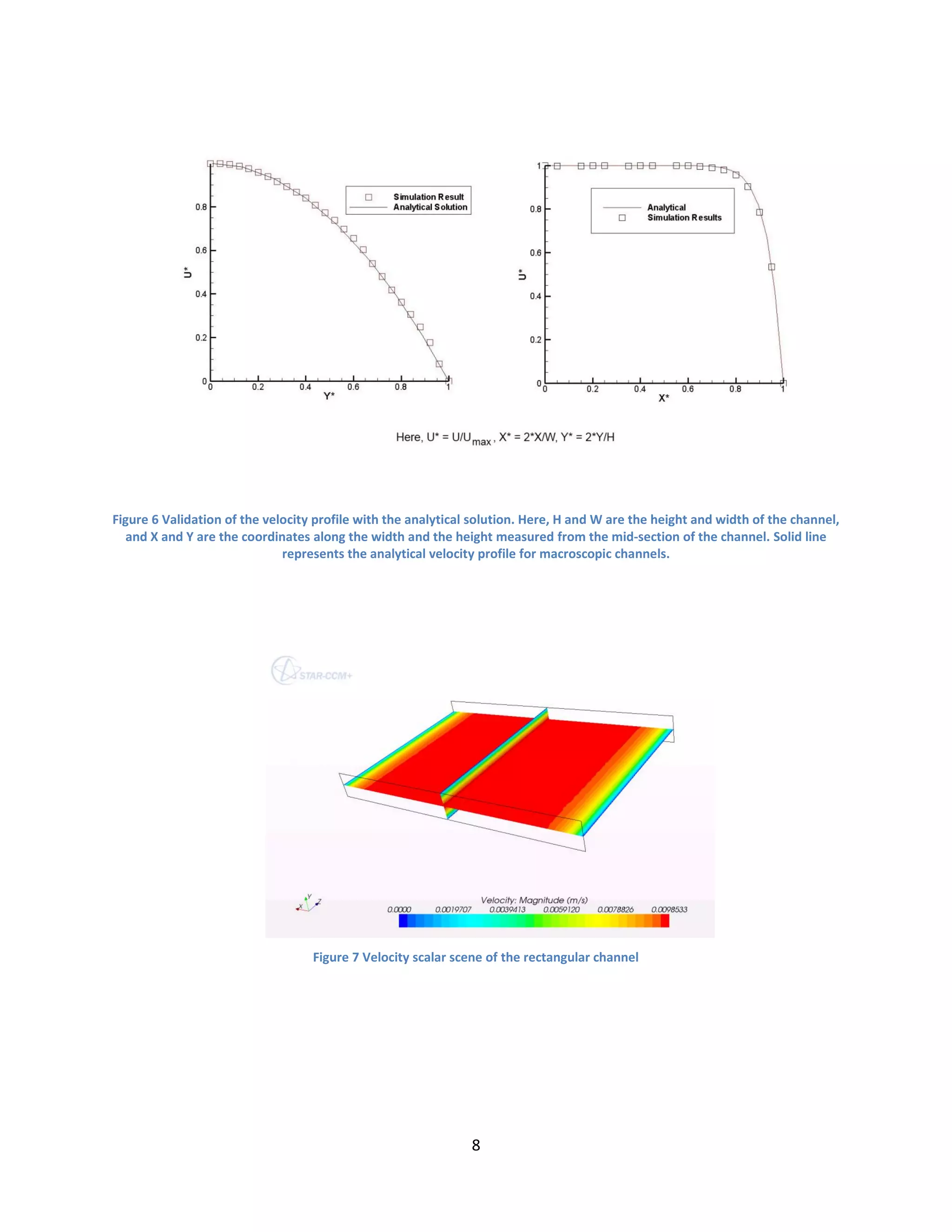
Firstly, flow characteristics (velocity profile and pressure gradient) of simple flow in
Microchannels of rectangular and circular cross section were validated.
After validating the single phase flow model, multiphase flow in Microchannels was validated by
modeling Droplet formation in a Microfluidic T-junction and a Microfluidic flow focusing
device.
A schematic diagram of T-junction is shown in fig. 1. The T-junction geometry consists of a
main channel and a dispersed channel that merge at a right angle. The main channel carries the
continuous fluid (carrier fluid), while the dispersed channel carries the dispersed phase. The T-
junction uses shearing action or pressure forces or both to form Droplets.](https://image.slidesharecdn.com/c31befc8-3cf6-408d-95b0-596d8b0fde70-160620044534/75/HarpreetMatharoo_IITDelhi-2-2048.jpg)
![2
A schematic of the flow focusing device is shown in fig. 2. There are three inlets to the device
out of which, the outer ones carry the continuous fluid and the inner one carry the dispersed
fluid. The interface is disturbed by forcing the three liquid streams to move through an orifice
placed at a certain distance from the inlet. Depending upon the flow parameters and geometrical
parameters, the disturbance might lead to the breakup of the inner liquid stream into small
droplets, which then flow downstream into the collection tube.
Both the geometries were modeled using Volume of fluid (VOF) because of its ability to
accommodate large surface topology changes including surface rupture and coalescence. Star-
CCM+ was successfully able to model the T-junction, however, very high spurious currents were
observed at the interface and to reduce these currents, adaptive mesh refinement (AMR)
technique was used to model the flow focusing device.
Methodology
Single Phase Flow
Incompressible laminar 3-D Navier-Stokes equations for pressure driven water flow were solved.
Also, no slip at the wall, velocity inlet and pressure outlet were imposed. Periodic boundary
condition was imposed for the rectangular channel, while for circular channel developed velocity
profile for macroscopic channel was imposed at the inlet.
Multiphase Flow and Droplet Formation
Study of droplet formation through numerical modeling imposes a great challenge because of the
complex interfacial dynamics and the formation of singularity at the time of interface breakup
[1]. There have been plenty of methods of available to model droplet formation, which can be](https://image.slidesharecdn.com/c31befc8-3cf6-408d-95b0-596d8b0fde70-160620044534/75/HarpreetMatharoo_IITDelhi-3-2048.jpg)
![3
categorized into two categories: Sharp interface methods and diffuse interface methods [1]. The
problem of modeling past transition of Droplet formation arises in case of sharp interface
methods because of the formation of singularity at the surface break-up. However, the surface
breakup is implicitly modeled in case of diffuse interface methods, while solving the governing
equations. One of such diffuse interface methods is Volume of fluid (VOF).
Volume of Fluid (VOF)
The VOF is well known for its ability to conserve the mass of the traced fluid and to
accommodate great surface topology changes. This change is traced easily, so the interfaces can
for example join, or break apart.
Mathematical formulation of VOF involves defining a color function C, which assumes a value
of 1 in one phase, 0 in another and fractional value at the interface [3]. Fig. 3 demonstrates how
‘C’ varies with the volume fraction of the fluid.
The properties of the fluid in the domain are defined as the function of C. Any general property
at any grid point is defined as:
( )
Where are the properties of fluids ‘c’ and ‘d’ respectively.
VOF solver involves an additional advection equation along with the momentum equations and
the continuity equation. The advection equation is as follows:](https://image.slidesharecdn.com/c31befc8-3cf6-408d-95b0-596d8b0fde70-160620044534/75/HarpreetMatharoo_IITDelhi-4-2048.jpg)
![5
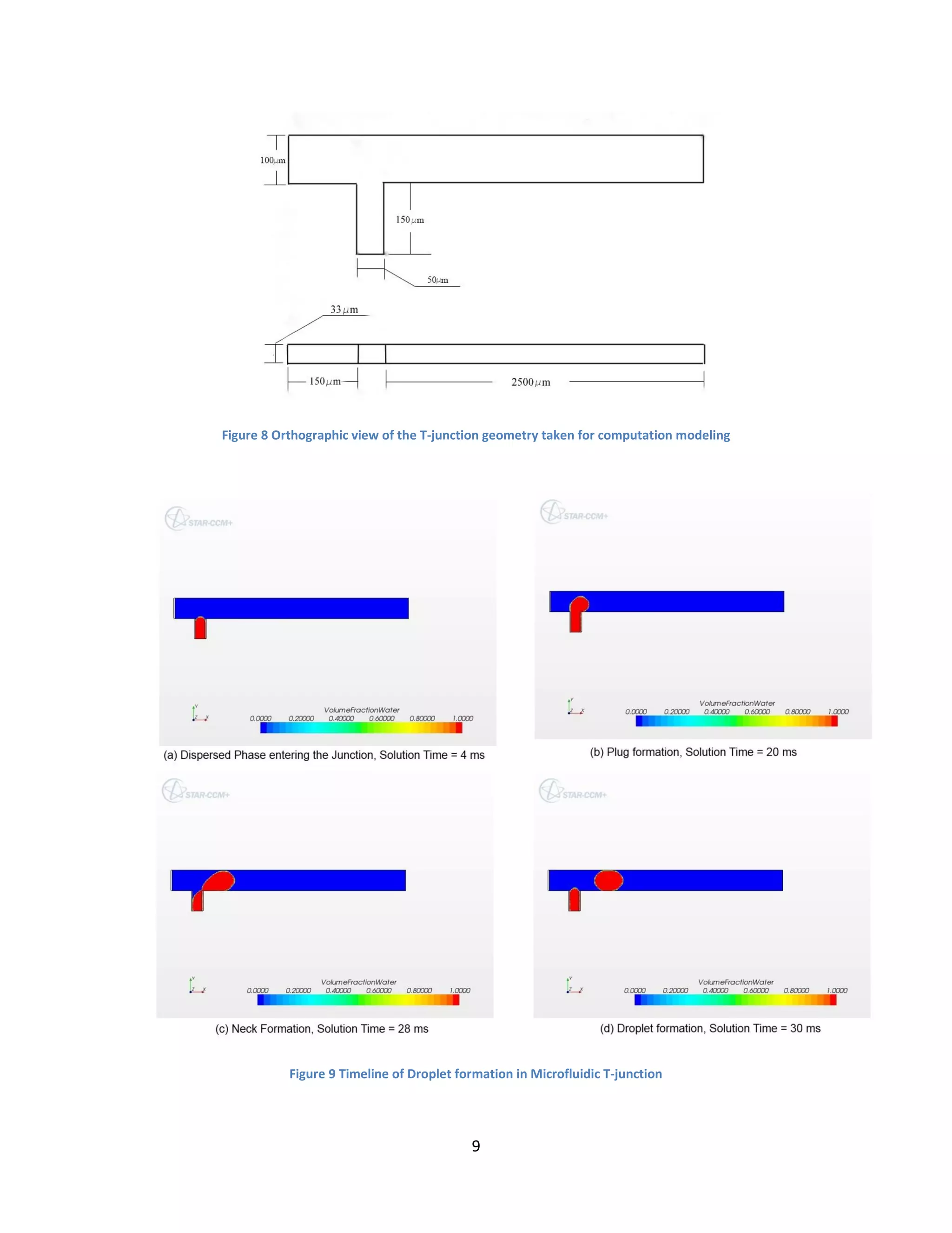
Microfluidic T-junction
The dimensions of microfluidic T-junction are takes as shown in fig. 8. The flow rate ratio
( ⁄ ) and Ca ( ⁄ ), where the subscripts ‘c’ and ‘d’ represent the continuous fluid and
the dispersed fluid respectively, were taken to be 0.25 and 5x10⁻³
respectively. Since, the
capillary number was very small, the droplet formation for this case was surface forces
dominated and the role of viscous forces in droplet formation was negligible.
Fig. 9 shows a timeline of droplet formation in microfluidic T-junction. The droplet size and the
mechanism of break-up is exactly the same as predicted by Garstecki et al [4]. However, very
high spurious currents were observed at the interface, because of which the time step was
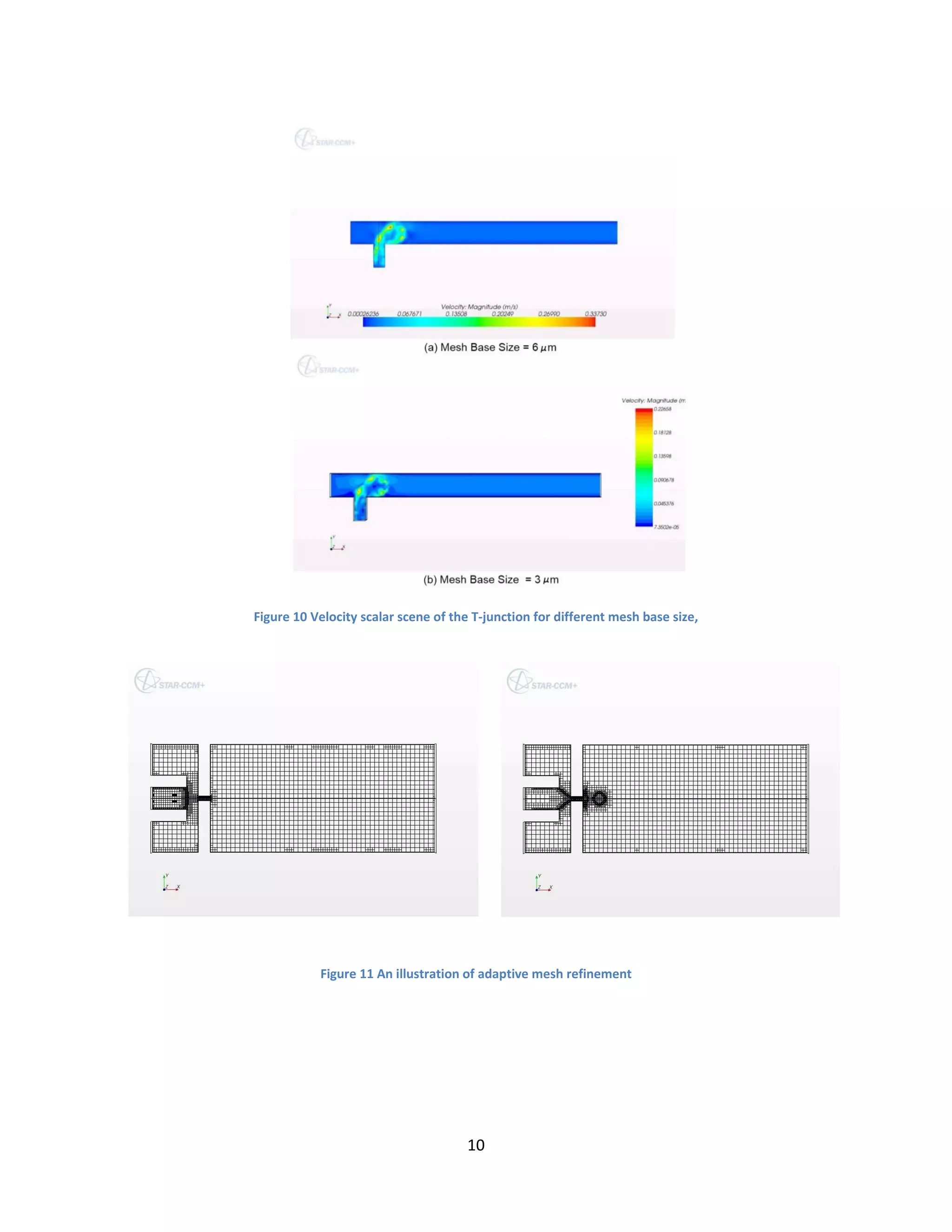
reduced to satisfy the CFL condition. Velocity scalar scenes for same interface location and
different mesh sizes are shown in fig 10. It can be seen that the spurious currents tend to decrease
as a finer mesh is taken.
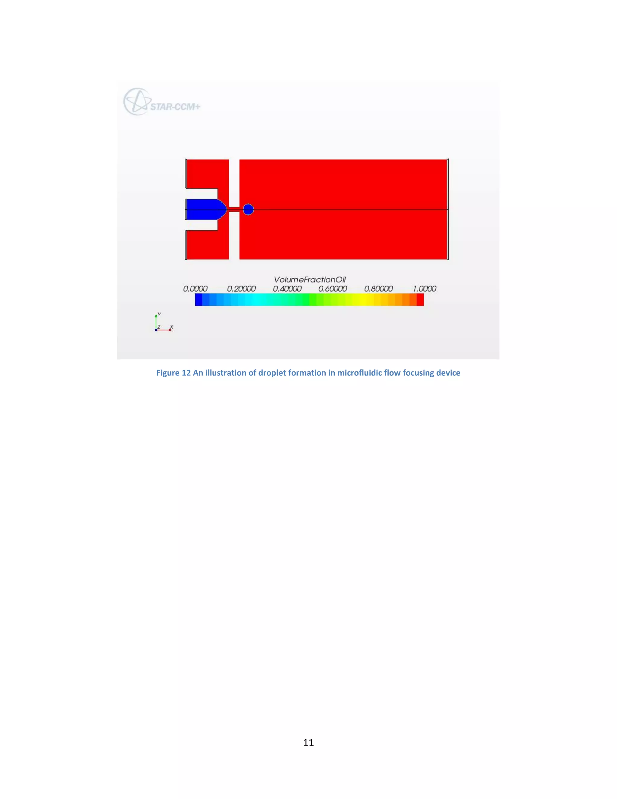
Microfluidic Flow Focusing Device
Dimensions of the device are as same as the one taken by Shelly et al [5]. The flow rate ratio and
Ca were taken to be 0.25 and 7.2X10⁻³
. Star-CCM+ successfully modeled the device within
reasonable computation time.
Also, based on the observation of T-junction modeling, adaptive mesh refinement technique is
applied. The mesh is made very fine near the interface and the mesh changes as the interface
moves. Fig. 11 shows a series of snapshots of the mesh as the dispersed phase advances in the
device. Because of a very fine dynamic mesh, a thin interface is obtained. Since, the mesh is very
fine at the interface the spurious currents are minimized, which saves the computation time. So,](https://image.slidesharecdn.com/c31befc8-3cf6-408d-95b0-596d8b0fde70-160620044534/75/HarpreetMatharoo_IITDelhi-6-2048.jpg)


![18 japan2012 milovan peric vof[1]](https://cdn.slidesharecdn.com/ss_thumbnails/18japan2012milovanpericvof1-130307124411-phpapp01-thumbnail.jpg?width=640&height=640&fit=bounds)


