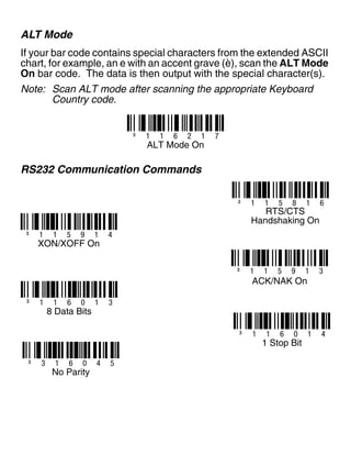
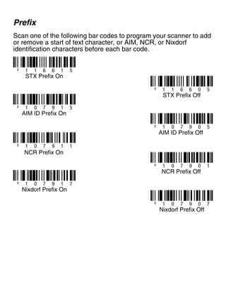
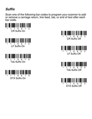
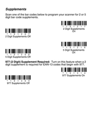
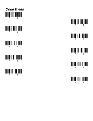
Voyager 9520/40
Voyager GS9590
Eclipse 5145
Quick Start Guide
VG-ECL-QS Rev B
10/11
Aller à www.honeywellaidc.com pour le français.
Vai a www.honeywellaidc.com per l'italiano.
Gehe zu www.honeywellaidc.com für Deutsch.
Ir a www.honeywellaidc.com para español.
Para Português, acesse www.honeywellaidc.com.br.
Перейти на русскоязычный сайт www.honeywellaidc.com.
日本語 : www.honeywellaidc.com をご覧ください。
如要到中国 www.honeywellaidc.com(简体)。
한글 www.honeywellaidc.com 로 이동합니다 .
Getting Started
Turn off the computer’s power before connecting the scanner, then
power up the computer once the scanner is fully connected.
Connecting the Scanner
USB:
Serial
(RS232):
Keyboard
Wedge:
optional adapter cable
Reading Techniques
Recall Defaults
Scan Enable Factory Defaults, then Recall Defaults to reset all
standard product default settings.
Interface Selections
USB
³ 9 9 9 9 9 8
Recall Defaults
³ 8 4 6 6 0 0
Enable Factory Defaults
³ 9 9 9 9 7 0
³ 3 1 6 4 0 0
USB Keyboard
Emulation
Load Integrated Full
Speed USB IBM/OEM
Defaults ³ 3 1 6 4 6 0
USB Serial Emulation
Keyboard Wedge
Keyboard Country
Scan a bar code to select one of the following keyboard country
templates. Refer to your Configuration Guide for additional keyboard
country settings.
³ 5 1 5 5 1 4 3
Keyboard Wedge Emulation
³ 4 1 6 2 1 0
³ 4 1 6 2 2 0
United Kingdom
³ 4 1 6 2 3 0
Germany/Austria
France
³ 4 1 6 2 6 0
United States
³ 4 1 6 2 0 0
Belgium
³ 4 1 6 2 5 0
Spain
³ 4 1 6 2 4 0
Italy
ALT Mode
If your bar code contains special characters from the extended ASCII
chart, for example, an e with an accent grave (è), scan the ALT Mode
On bar code. The data is then output with the special character(s).
Note: Scan ALT mode after scanning the appropriate Keyboard
Country code.
RS232 Communication Commands
³ 1 1 6 2 1 7
ALT Mode On
³ 1 1 5 8 1 6
RTS/CTS
Handshaking On
³ 1 1 5 9 1 4
XON/XOFF On
³ 1 1 5 9 1 3
ACK/NAK On
³ 1 1 6 0 1 3
8 Data Bits
³ 1 1 6 0 1 4
1 Stop Bit
³ 3 1 6 0 4 5
No Parity
Prefix
Scan one of the following bar codes to program your scanner to add
or remove a start of text character, or AIM, NCR, or Nixdorf
identification characters before each bar code.
³ 1 1 6 6 1 5
³ 1 1 6 6 0 5
³ 1 0 7 9 0 5
³ 1 0 7 9 0 1
STX Prefix On
STX Prefix Off
³ 1 0 7 9 1 5
AIM ID Prefix On
AIM ID Prefix Off
³ 1 0 7 9 1 1
NCR Prefix On
NCR Prefix Off
³ 1 0 7 9 0 7
³ 1 0 7 9 1 7
Nixdorf Prefix On
Nixdorf Prefix Off
Suffix
Scan one of the following bar codes to program your scanner to add
or remove a carriage return, line feed, tab, or end of text after each
bar code.
³ 1 1 6 6 1 3
³ 1 1 6 6 0 3
³ 1 1 6 6 0 4
CR Suffix On
CR Suffix Off
³ 1 1 6 6 1 2
LF Suffix On
³ 1 1 6 6 0 2
LF Suffix Off
³ 1 1 6 6 1 0
Tab Suffix On
³ 1 1 6 6 0 0
Tab Suffix Off
³ 1 1 6 6 1 4
ETX Suffix On
ETX Suffix Off
User Configurable Prefix/Suffix
One or two prefix or suffix characters can be added and assigned for
data transmission. Use one of the codes below with a 3 code byte
sequence that represents the desired character (see ASCII
Conversion Chart, end of document) for your prefix or suffix. (To add
additional prefix/suffix characters, refer to your Single-Line
Configuration Guide.)
Scan the Enter/Exit Programming bar code to begin. Then scan
the 3 digit decimal equivalent of the ASCII character into the
appropriate character location with the code byte bar codes (see
Code Bytes, end of document). To save, scan the Enter/Exit
Programming bar code again.
Example: To add an asterisk (*) as a prefix, scan the bar codes:
1. Enter/Exit Programming
2. Configurable Prefix #1
3. Code Byte 0
4. Code Byte 4
5. Code Byte 2
6. Enter/Exit Programming
³ 9 0 4 5 0 0
Configurable Suffix #1
³ 9 0 4 6 0 0
Configurable Suffix #2
³ 9 0 3 5 0 0
Configurable Prefix #1
³ 9 0 3 6 0 0
Configurable Prefix #2
³ 9 9 9 9 9 9
Enter/Exit Programming
Supplements
Scan one of the bar codes below to program your scanner for 2 or 5
digit bar code supplements.
977 (2 Digit) Supplement Required: Turn on this feature when a 2
digit supplement is required for EAN-13 codes that begin with 977.
³ 1 0 1 2 1 7
2 Digit Supplements
On
³ 1 0 1 2 0 7
2 Digit Supplements Off
³ 1 0 1 2 1 6
5 Digit Supplements
On
³ 1 0 1 2 0 6
5 Digit Supplements Off
³ 1 0 1 3 1 4
977 Supplements On
³ 1 0 1 3 0 4
977 Supplements Off
UPC/EAN Formatting
Scan Convert UPC-A to EAN-13 and a leading zero is transmitted
before a UPC-A bar code to convert it to EAN-13.
Scan Transmit Lead Zero on UPC-E to transmit a zero before each
UPC-E bar code.
Scan Transmit UPC-A Number System to transmit the UPC-A
leading digit with the bar code data. To transmit just the data, without
the leading digit, scan Don’t Transmit UPC-A Number System.
³ 1 0 7 5 1 4
Convert UPC-A to
EAN-13
³ 1 0 7 5 0 4
Don’t Convert UPC-A to
EAN-13
³ 1 0 7 5 1 3
Transmit Lead Zero on
UPC-E
³ 1 0 7 5 0 3
Don’t Transmit Lead
Zero on UPC-E
³ 1 0 7 5 1 1
³ 1 0 7 5 0 1
Don’t Transmit UPC-A
Number System
Transmit UPC-A
Number System
Expand UPC-E to 12 Digits expands the UPC-E code to the 12 digit,
UPC-A format.
When Code 39 Full ASCII On is scanned, certain character pairs
within the bar code symbol will be interpreted as a single character.
For example: $V will be decoded as the ASCII character SYN, and /
C will be decoded as the ASCII character #.
³ 1 0 7 5 1 5
Expand UPC-E to 12
Digits
³ 1 0 7 5 0 5
Don’t Expand UPC-E to
12 Digits
³ 1 0 0 2 1 7
Code 39 Full ASCII On
³ 1 0 0 2 0 7
Code 39 Full ASCII Off
Check Digits
The following selections allow you to specify whether the check digit
should be transmitted at the end of the scanned UPC-A or UPC-E
data or not.
CodeGate/Manual Activation
Use the following programming codes to control CodeGate button/
trigger functions. Any time CodeGate is Active, you must push the
CodeGate button (on the top of the scanner)or press the trigger to
read a bar code. Whenever CodeGate is Inactive, the CodeGate
button/trigger does not need to be pressed. Bar codes are
automatically read when they are in the scanner’s field of view.
³ 1 0 7 5 1 7
³ 1 0 7 5 0 7
Don’t Transmit UPC-A
Check Digits
*Transmit UPC-A
Check Digits
³ 1 0 7 5 1 6
³ 1 0 7 5 0 6
*Don’t Transmit UPC-E
Check Digits
Transmit UPC-E Check
Digits
³ 1 1 8 7 0 3
³ 1 1 8 7 1 3
CodeGate Active Out
of Stand
CodeGate Inactive Out
of Stand
Host Configurations
Scan one of the following codes, then scan the Recall Defaults
code, to program the scanner for one of the following configurations.
Miscellaneous
Minimum Symbol Length specifies the minimum number of
characters allowable for non-UPC/EAN bar codes. Scan the Enter/
Exit Programming bar code to begin. Scan Minimum Symbol
Length, then scan the minumum number of characters allowed using
code byte bar codes, below. To save, scan the Enter/Exit
Programming bar code again.
³ 8 4 6 6 1 2 8 0
³ 8 4 6 6 0 0 3 0
³ 8 4 6 6 0 1 4 0
Verifone® Ruby Terminal
Defaults
Gilbarco® Terminal
Defaults
Wincor Nixdorf Terminal
Defaults
³ 9 9 9 9 9 8
Recall Defaults
³ 9 0 1 8 0 0
Minimum Symbol Length
³ 9 9 9 9 9 9
Enter/Exit Programming
Code Bytes
³ 0
³ 1
³ 3
³ 5
³ 2
³ 4
³ 6
³ 7
³ 9
³ 8
ASCII Conversion Chart
Dec Hex Char Dec Hex Char Dec Hex Char Dec Hex Char Dec Hex Char
0 00 NUL 26 1A SUB 52 34 4 78 4E N 104 68 h
1 01 SOH 27 1B ESC 53 35 5 79 4F O 105 69 i
2 02 STX 28 1C FS 54 36 6 80 50 P 106 6A j
3 03 ETX 29 1D GS 55 37 7 81 51 Q 107 6B k
4 04 EOT 30 1E RS 56 38 8 82 52 R 108 6C l
5 05 ENQ 31 1F US 57 39 9 83 53 S 109 6D m
6 06 ACK 32 20 58 3A : 84 54 T 110 6E n
7 07 BEL 33 21 ! 59 3B ; 85 55 U 111 6F o
8 08 BS 34 22 “ 60 3C < 86 56 V 112 70 p
9 09 HT 35 23 # 61 3D = 87 57 W 113 71 q
10 0A LF 36 24 $ 62 3E > 88 58 X 114 72 r
11 0B VT 37 25 % 63 3F ? 89 59 Y 115 73 s
12 0C FF 38 26 & 64 40 @ 90 5A Z 116 74 t
13 0D CR 39 27 ‘ 65 41 A 91 5B [ 117 75 u
14 0E SO 40 28 ( 66 42 B 92 5C  118 76 v
15 0F SI 41 29 ) 67 43 C 93 5D ] 119 77 w
16 10 DLE 42 2A * 68 44 D 94 5E ^ 120 78 x
17 11 DC1 43 2B + 69 45 E 95 5F _ 121 79 y
18 12 DC2 44 2C , 70 46 F 96 60 ‘ 122 7A z
19 13 DC3 45 2D - 71 47 G 97 61 a 123 7B {
20 14 DC4 46 2E . 72 48 H 98 62 b 124 7C |
21 15 NAK 47 2F / 73 49 l 99 63 c 125 7D }
22 16 SYN 48 30 0 74 4A J 100 64 d 126 7E ~
23 17 ETB 49 31 1 75 4B K 101 65 e 127 7F
24 18 CAN 50 32 2 76 4C L 102 66 f
25 19 EM 51 33 3 77 4D M 103 67 g
Technical Assistance
Contact information for technical support, product service, and repair can be
found at www.honeywellaidc.com.
Limited Warranty
Refer to www.honeywellaidc.com/warranty_information for your product’s
warranty information.
User Documentation
For localized versions of this document, and to download the Configuration
Guide or the Installation and User’s Guide, go to www.honeywellaidc.com.
Disclaimer
Honeywell International Inc. (“HII”) reserves the right to make changes in specifications and other
information contained in this document without prior notice, and the reader should in all cases consult
HII to determine whether any such changes have been made. The information in this publication does
not represent a commitment on the part of HII.
HII shall not be liable for technical or editorial errors or omissions contained herein; nor for incidental or
consequential damages resulting from the furnishing, performance, or use of this material.
This document contains proprietary information that is protected by copyright. All rights are reserved.
No part of this document may be photocopied, reproduced, or translated into another language without
the prior written consent of HII.
© 2010-2011 Honeywell International Inc. All rights reserved.
Web Address: www.honeywellaidc.com

Guia de configuracao_ms9520

  • 1.
    Voyager 9520/40 Voyager GS9590 Eclipse5145 Quick Start Guide VG-ECL-QS Rev B 10/11 Aller à www.honeywellaidc.com pour le français. Vai a www.honeywellaidc.com per l'italiano. Gehe zu www.honeywellaidc.com für Deutsch. Ir a www.honeywellaidc.com para español. Para Português, acesse www.honeywellaidc.com.br. Перейти на русскоязычный сайт www.honeywellaidc.com. 日本語 : www.honeywellaidc.com をご覧ください。 如要到中国 www.honeywellaidc.com(简体)。 한글 www.honeywellaidc.com 로 이동합니다 .
  • 2.
    Getting Started Turn offthe computer’s power before connecting the scanner, then power up the computer once the scanner is fully connected. Connecting the Scanner USB: Serial (RS232): Keyboard Wedge: optional adapter cable
  • 3.
    Reading Techniques Recall Defaults ScanEnable Factory Defaults, then Recall Defaults to reset all standard product default settings. Interface Selections USB ³ 9 9 9 9 9 8 Recall Defaults ³ 8 4 6 6 0 0 Enable Factory Defaults ³ 9 9 9 9 7 0 ³ 3 1 6 4 0 0 USB Keyboard Emulation Load Integrated Full Speed USB IBM/OEM Defaults ³ 3 1 6 4 6 0 USB Serial Emulation
  • 4.
    Keyboard Wedge Keyboard Country Scana bar code to select one of the following keyboard country templates. Refer to your Configuration Guide for additional keyboard country settings. ³ 5 1 5 5 1 4 3 Keyboard Wedge Emulation ³ 4 1 6 2 1 0 ³ 4 1 6 2 2 0 United Kingdom ³ 4 1 6 2 3 0 Germany/Austria France ³ 4 1 6 2 6 0 United States ³ 4 1 6 2 0 0 Belgium ³ 4 1 6 2 5 0 Spain ³ 4 1 6 2 4 0 Italy
  • 5.
    ALT Mode If yourbar code contains special characters from the extended ASCII chart, for example, an e with an accent grave (è), scan the ALT Mode On bar code. The data is then output with the special character(s). Note: Scan ALT mode after scanning the appropriate Keyboard Country code. RS232 Communication Commands ³ 1 1 6 2 1 7 ALT Mode On ³ 1 1 5 8 1 6 RTS/CTS Handshaking On ³ 1 1 5 9 1 4 XON/XOFF On ³ 1 1 5 9 1 3 ACK/NAK On ³ 1 1 6 0 1 3 8 Data Bits ³ 1 1 6 0 1 4 1 Stop Bit ³ 3 1 6 0 4 5 No Parity
  • 6.
    Prefix Scan one ofthe following bar codes to program your scanner to add or remove a start of text character, or AIM, NCR, or Nixdorf identification characters before each bar code. ³ 1 1 6 6 1 5 ³ 1 1 6 6 0 5 ³ 1 0 7 9 0 5 ³ 1 0 7 9 0 1 STX Prefix On STX Prefix Off ³ 1 0 7 9 1 5 AIM ID Prefix On AIM ID Prefix Off ³ 1 0 7 9 1 1 NCR Prefix On NCR Prefix Off ³ 1 0 7 9 0 7 ³ 1 0 7 9 1 7 Nixdorf Prefix On Nixdorf Prefix Off
  • 7.
    Suffix Scan one ofthe following bar codes to program your scanner to add or remove a carriage return, line feed, tab, or end of text after each bar code. ³ 1 1 6 6 1 3 ³ 1 1 6 6 0 3 ³ 1 1 6 6 0 4 CR Suffix On CR Suffix Off ³ 1 1 6 6 1 2 LF Suffix On ³ 1 1 6 6 0 2 LF Suffix Off ³ 1 1 6 6 1 0 Tab Suffix On ³ 1 1 6 6 0 0 Tab Suffix Off ³ 1 1 6 6 1 4 ETX Suffix On ETX Suffix Off
  • 8.
    User Configurable Prefix/Suffix Oneor two prefix or suffix characters can be added and assigned for data transmission. Use one of the codes below with a 3 code byte sequence that represents the desired character (see ASCII Conversion Chart, end of document) for your prefix or suffix. (To add additional prefix/suffix characters, refer to your Single-Line Configuration Guide.) Scan the Enter/Exit Programming bar code to begin. Then scan the 3 digit decimal equivalent of the ASCII character into the appropriate character location with the code byte bar codes (see Code Bytes, end of document). To save, scan the Enter/Exit Programming bar code again. Example: To add an asterisk (*) as a prefix, scan the bar codes: 1. Enter/Exit Programming 2. Configurable Prefix #1 3. Code Byte 0 4. Code Byte 4 5. Code Byte 2 6. Enter/Exit Programming ³ 9 0 4 5 0 0 Configurable Suffix #1 ³ 9 0 4 6 0 0 Configurable Suffix #2 ³ 9 0 3 5 0 0 Configurable Prefix #1 ³ 9 0 3 6 0 0 Configurable Prefix #2 ³ 9 9 9 9 9 9 Enter/Exit Programming
  • 9.
    Supplements Scan one ofthe bar codes below to program your scanner for 2 or 5 digit bar code supplements. 977 (2 Digit) Supplement Required: Turn on this feature when a 2 digit supplement is required for EAN-13 codes that begin with 977. ³ 1 0 1 2 1 7 2 Digit Supplements On ³ 1 0 1 2 0 7 2 Digit Supplements Off ³ 1 0 1 2 1 6 5 Digit Supplements On ³ 1 0 1 2 0 6 5 Digit Supplements Off ³ 1 0 1 3 1 4 977 Supplements On ³ 1 0 1 3 0 4 977 Supplements Off
  • 10.
    UPC/EAN Formatting Scan ConvertUPC-A to EAN-13 and a leading zero is transmitted before a UPC-A bar code to convert it to EAN-13. Scan Transmit Lead Zero on UPC-E to transmit a zero before each UPC-E bar code. Scan Transmit UPC-A Number System to transmit the UPC-A leading digit with the bar code data. To transmit just the data, without the leading digit, scan Don’t Transmit UPC-A Number System. ³ 1 0 7 5 1 4 Convert UPC-A to EAN-13 ³ 1 0 7 5 0 4 Don’t Convert UPC-A to EAN-13 ³ 1 0 7 5 1 3 Transmit Lead Zero on UPC-E ³ 1 0 7 5 0 3 Don’t Transmit Lead Zero on UPC-E ³ 1 0 7 5 1 1 ³ 1 0 7 5 0 1 Don’t Transmit UPC-A Number System Transmit UPC-A Number System
  • 11.
    Expand UPC-E to12 Digits expands the UPC-E code to the 12 digit, UPC-A format. When Code 39 Full ASCII On is scanned, certain character pairs within the bar code symbol will be interpreted as a single character. For example: $V will be decoded as the ASCII character SYN, and / C will be decoded as the ASCII character #. ³ 1 0 7 5 1 5 Expand UPC-E to 12 Digits ³ 1 0 7 5 0 5 Don’t Expand UPC-E to 12 Digits ³ 1 0 0 2 1 7 Code 39 Full ASCII On ³ 1 0 0 2 0 7 Code 39 Full ASCII Off
  • 12.
    Check Digits The followingselections allow you to specify whether the check digit should be transmitted at the end of the scanned UPC-A or UPC-E data or not. CodeGate/Manual Activation Use the following programming codes to control CodeGate button/ trigger functions. Any time CodeGate is Active, you must push the CodeGate button (on the top of the scanner)or press the trigger to read a bar code. Whenever CodeGate is Inactive, the CodeGate button/trigger does not need to be pressed. Bar codes are automatically read when they are in the scanner’s field of view. ³ 1 0 7 5 1 7 ³ 1 0 7 5 0 7 Don’t Transmit UPC-A Check Digits *Transmit UPC-A Check Digits ³ 1 0 7 5 1 6 ³ 1 0 7 5 0 6 *Don’t Transmit UPC-E Check Digits Transmit UPC-E Check Digits ³ 1 1 8 7 0 3 ³ 1 1 8 7 1 3 CodeGate Active Out of Stand CodeGate Inactive Out of Stand
  • 13.
    Host Configurations Scan oneof the following codes, then scan the Recall Defaults code, to program the scanner for one of the following configurations. Miscellaneous Minimum Symbol Length specifies the minimum number of characters allowable for non-UPC/EAN bar codes. Scan the Enter/ Exit Programming bar code to begin. Scan Minimum Symbol Length, then scan the minumum number of characters allowed using code byte bar codes, below. To save, scan the Enter/Exit Programming bar code again. ³ 8 4 6 6 1 2 8 0 ³ 8 4 6 6 0 0 3 0 ³ 8 4 6 6 0 1 4 0 Verifone® Ruby Terminal Defaults Gilbarco® Terminal Defaults Wincor Nixdorf Terminal Defaults ³ 9 9 9 9 9 8 Recall Defaults ³ 9 0 1 8 0 0 Minimum Symbol Length ³ 9 9 9 9 9 9 Enter/Exit Programming
  • 14.
    Code Bytes ³ 0 ³1 ³ 3 ³ 5 ³ 2 ³ 4 ³ 6 ³ 7 ³ 9 ³ 8
  • 15.
    ASCII Conversion Chart DecHex Char Dec Hex Char Dec Hex Char Dec Hex Char Dec Hex Char 0 00 NUL 26 1A SUB 52 34 4 78 4E N 104 68 h 1 01 SOH 27 1B ESC 53 35 5 79 4F O 105 69 i 2 02 STX 28 1C FS 54 36 6 80 50 P 106 6A j 3 03 ETX 29 1D GS 55 37 7 81 51 Q 107 6B k 4 04 EOT 30 1E RS 56 38 8 82 52 R 108 6C l 5 05 ENQ 31 1F US 57 39 9 83 53 S 109 6D m 6 06 ACK 32 20 58 3A : 84 54 T 110 6E n 7 07 BEL 33 21 ! 59 3B ; 85 55 U 111 6F o 8 08 BS 34 22 “ 60 3C < 86 56 V 112 70 p 9 09 HT 35 23 # 61 3D = 87 57 W 113 71 q 10 0A LF 36 24 $ 62 3E > 88 58 X 114 72 r 11 0B VT 37 25 % 63 3F ? 89 59 Y 115 73 s 12 0C FF 38 26 & 64 40 @ 90 5A Z 116 74 t 13 0D CR 39 27 ‘ 65 41 A 91 5B [ 117 75 u 14 0E SO 40 28 ( 66 42 B 92 5C 118 76 v 15 0F SI 41 29 ) 67 43 C 93 5D ] 119 77 w 16 10 DLE 42 2A * 68 44 D 94 5E ^ 120 78 x 17 11 DC1 43 2B + 69 45 E 95 5F _ 121 79 y 18 12 DC2 44 2C , 70 46 F 96 60 ‘ 122 7A z 19 13 DC3 45 2D - 71 47 G 97 61 a 123 7B { 20 14 DC4 46 2E . 72 48 H 98 62 b 124 7C | 21 15 NAK 47 2F / 73 49 l 99 63 c 125 7D } 22 16 SYN 48 30 0 74 4A J 100 64 d 126 7E ~ 23 17 ETB 49 31 1 75 4B K 101 65 e 127 7F 24 18 CAN 50 32 2 76 4C L 102 66 f 25 19 EM 51 33 3 77 4D M 103 67 g
  • 16.
    Technical Assistance Contact informationfor technical support, product service, and repair can be found at www.honeywellaidc.com. Limited Warranty Refer to www.honeywellaidc.com/warranty_information for your product’s warranty information. User Documentation For localized versions of this document, and to download the Configuration Guide or the Installation and User’s Guide, go to www.honeywellaidc.com. Disclaimer Honeywell International Inc. (“HII”) reserves the right to make changes in specifications and other information contained in this document without prior notice, and the reader should in all cases consult HII to determine whether any such changes have been made. The information in this publication does not represent a commitment on the part of HII. HII shall not be liable for technical or editorial errors or omissions contained herein; nor for incidental or consequential damages resulting from the furnishing, performance, or use of this material. This document contains proprietary information that is protected by copyright. All rights are reserved. No part of this document may be photocopied, reproduced, or translated into another language without the prior written consent of HII. © 2010-2011 Honeywell International Inc. All rights reserved. Web Address: www.honeywellaidc.com