Downloaded 15 times
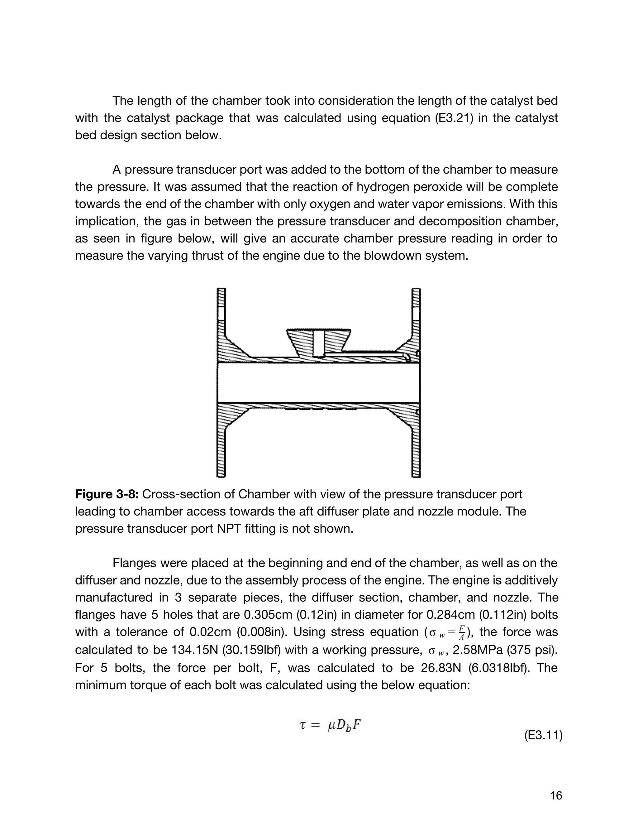
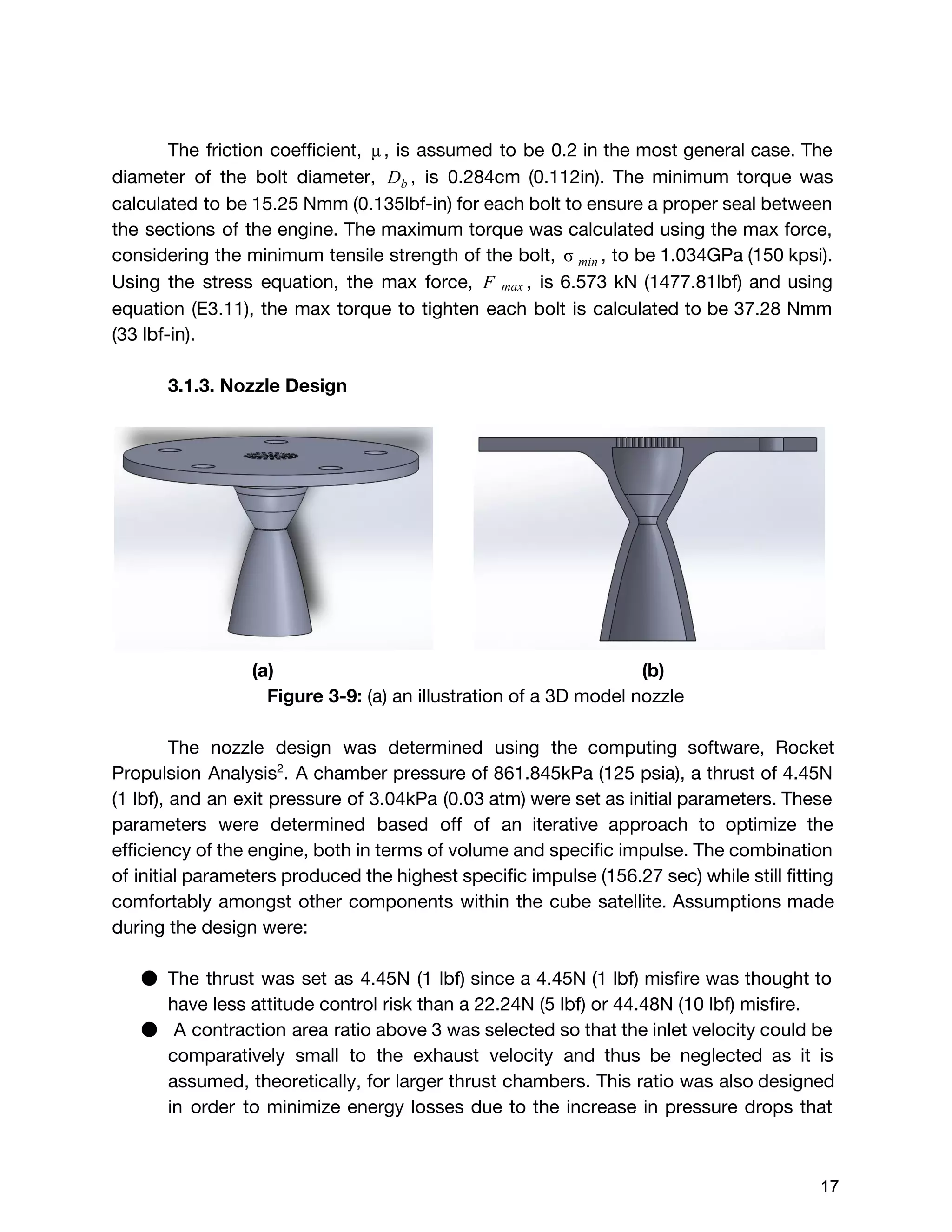
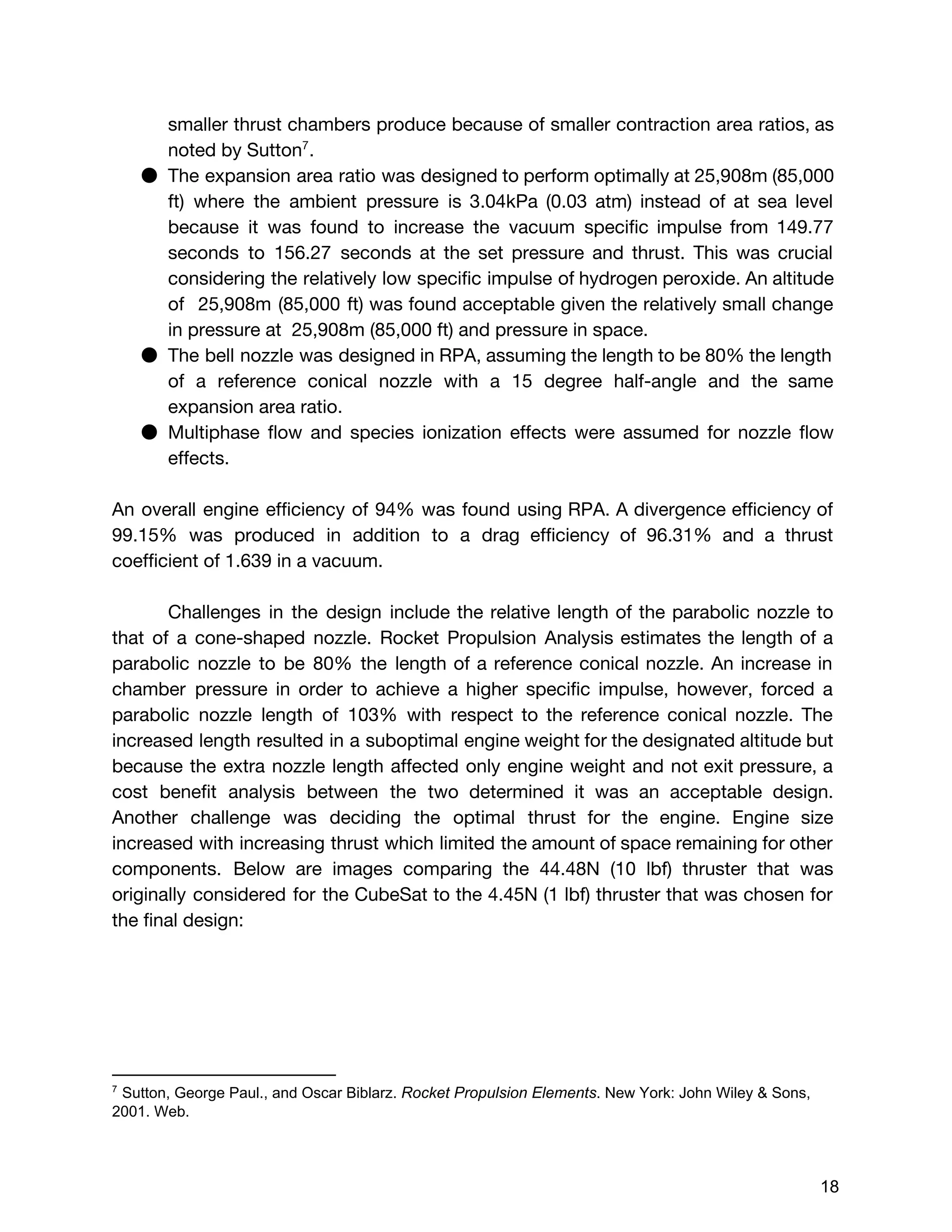
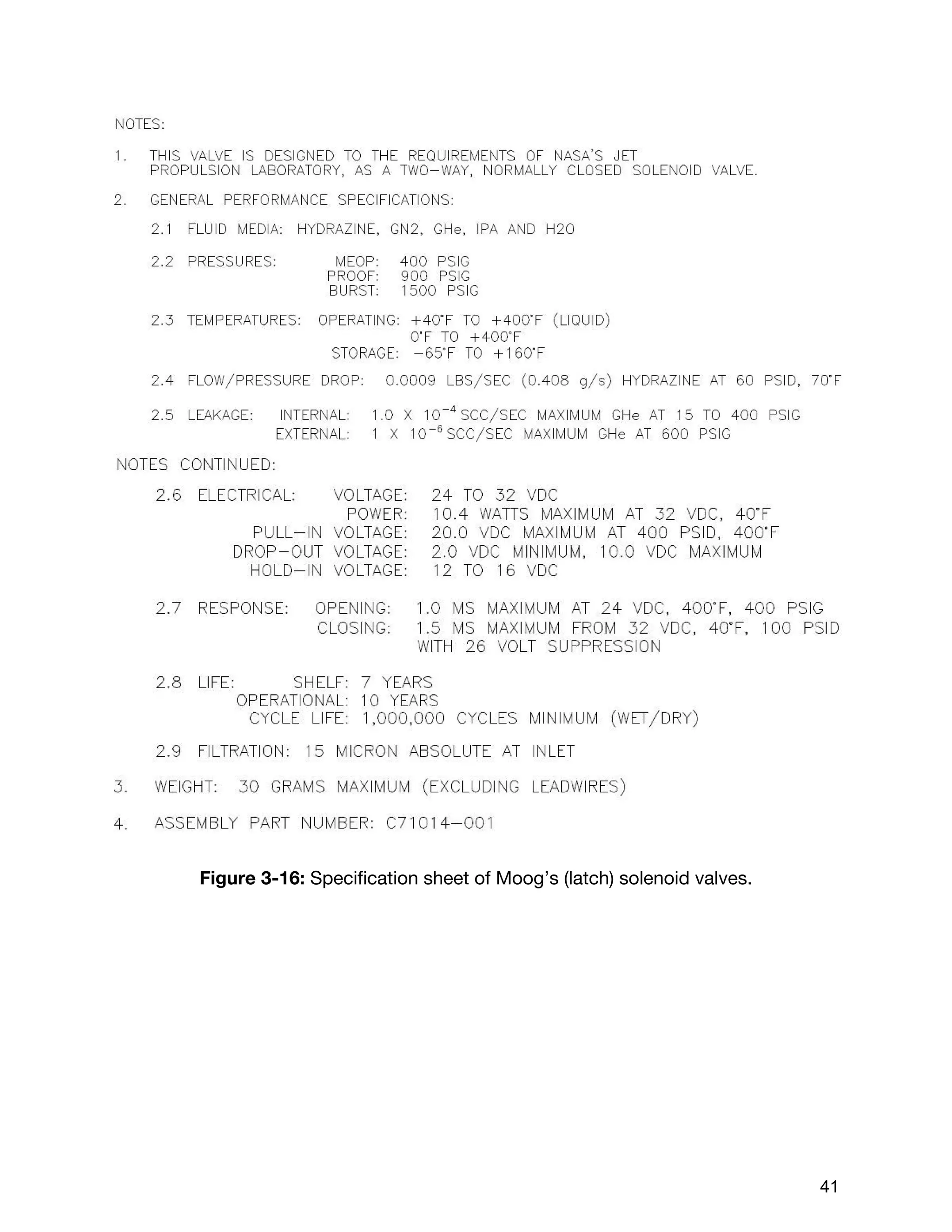
![2. Design Requirements
2.1 Volume
The CubeSat was allotted 3300 of volume within the 10cm x 20 cm x 30 cmcm3
structure, which the propellant feed system must be able to be constrained within the
given volume.
[SPS.SPL.003] Payloads shall not exceed a combined dispenser/payload (including
any thermal protection and vibration isolation) mass of 60 lbs (27.22 kg) for either a 6U
or 12U configuration.”
[SPS.SPL.004] Dispenser/Payload Center of Gravity. Payloads shall maintain a
combined dispenser/payload CG within the 6U or 12U enveloped in Table 3-1 and
depicted in Figure 3-4.
The system meets the center of gravity and maximum payload weight design
challenges, because the system has a symmetrical two-tank configuration and valve
assembly instead of one tank or an other arbitrary number of tanks. The dual tank
configuration allows the pressure vessels to hold less pressure than a one tank
configuration, thereby optimizing the thickness and weight of the tanks. This in turn
helps reduce tank length and allows the feed system to meet the volumetric
constraints of the CubeSat . Any tank configuration above two was eliminated because
the number of valves needed and the complexity of operation would outweigh (both
literally and figuratively) the benefits of smaller sized tanks.
[SPS.SPL.005]Dispenser/Payload Cleanliness. Payloads shall comply with the
GSDO-RQMT-1080, Cross-Program Contamination Control Requirements document
for visibly clean standard level.
The system meets the payload cleanliness design challenge because all fittings,
valves, tubes, and tanks that make up the system will be subject to oxidizer cleaning
by AstroPak. The process will include something similar to cleaning aluminum
components with sodium hydroxide, passivating the system with nitric acid, cleaning
the system with deionized water, and reviewing hydrogen peroxide properties for
compatibility36
. This also helps with contamination given the volatility of hydrogen
peroxide. The parts will be shipped for cleaning and will be later received by
SEDS@UCSD, and delivered to NASA under positive pressure with seals covering any
openings to prevent contamination.
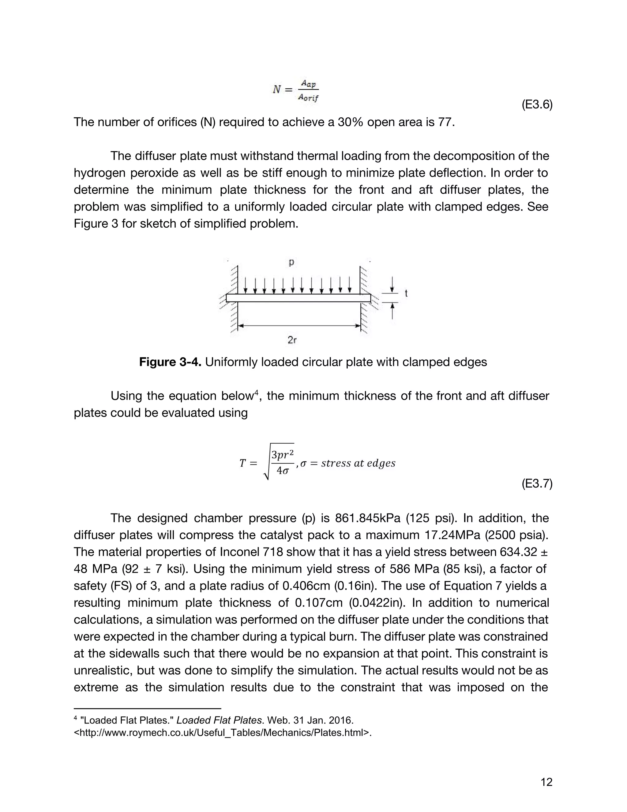
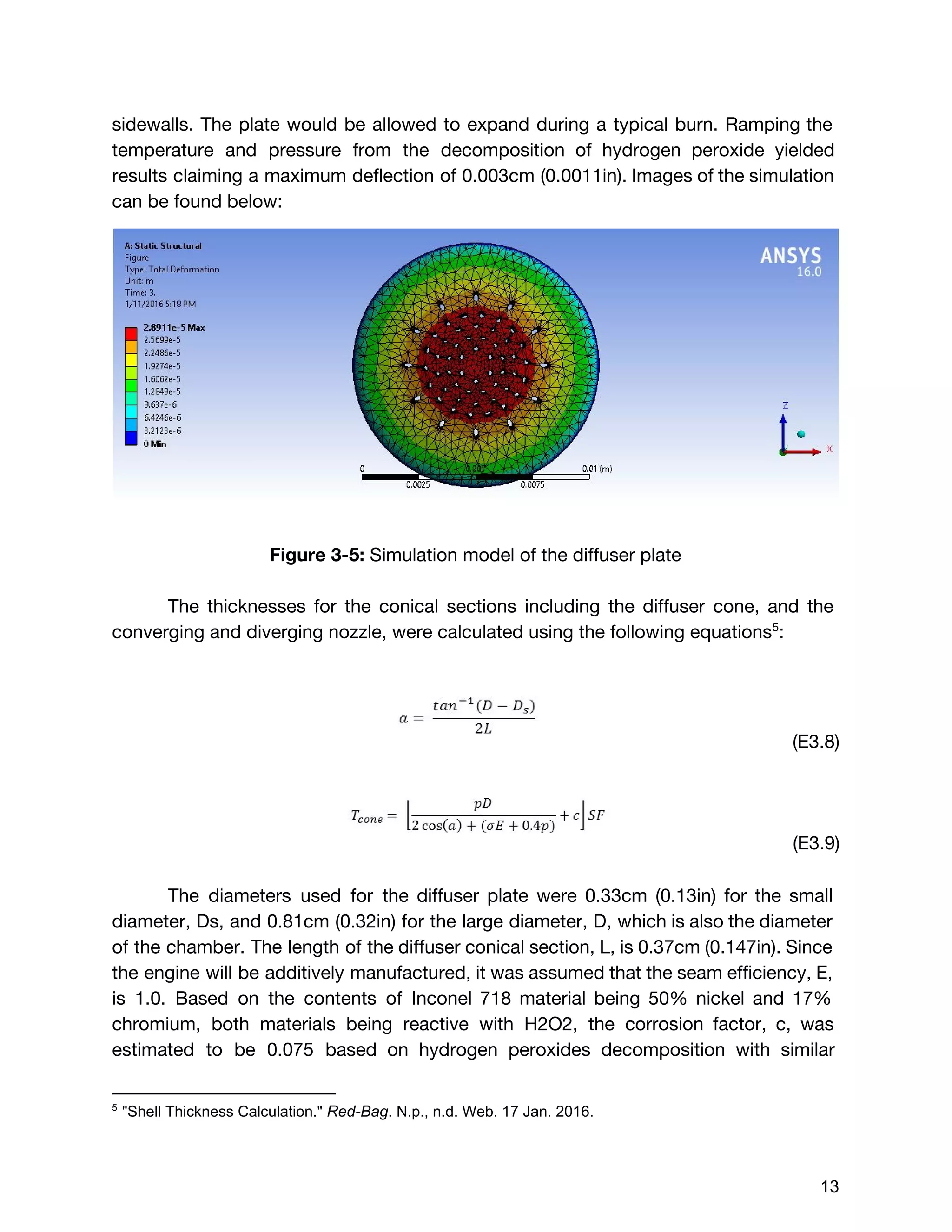
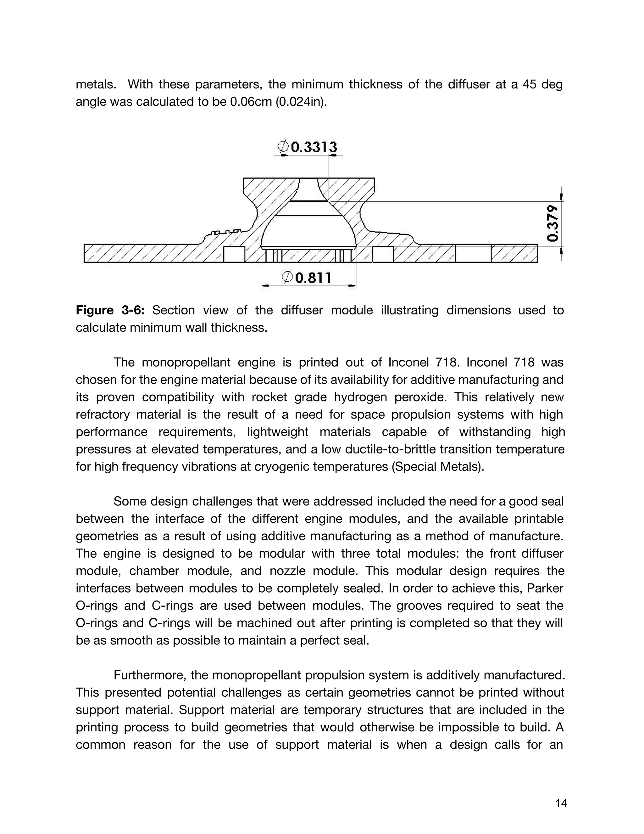
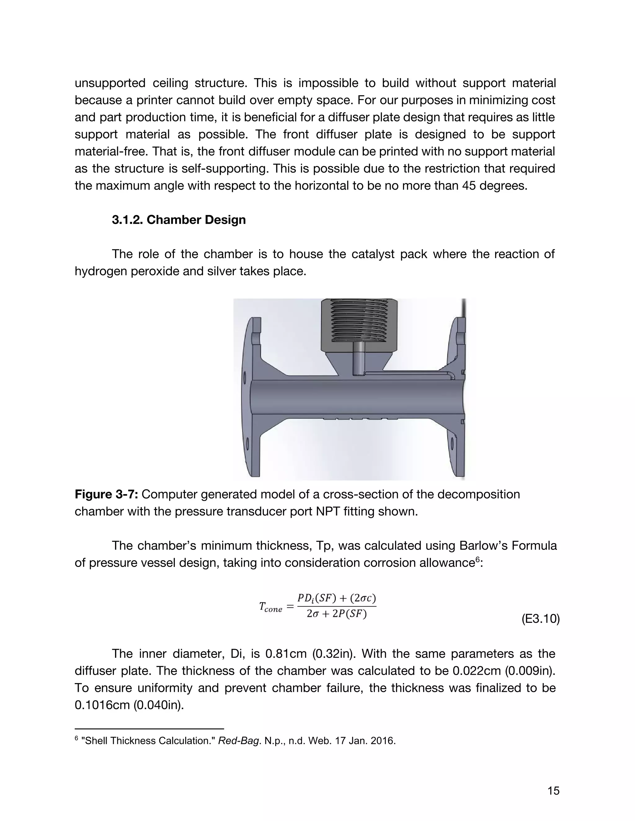
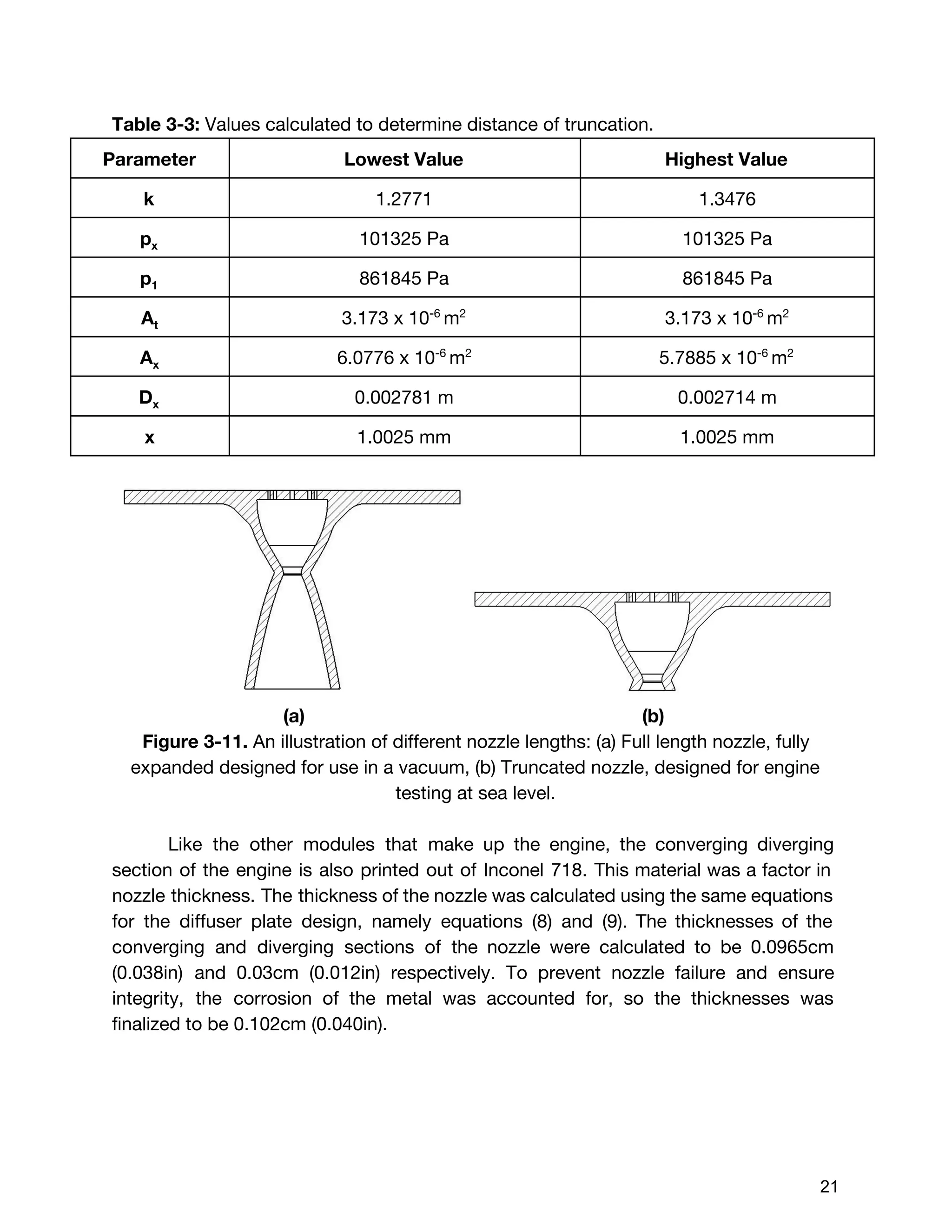
5](https://image.slidesharecdn.com/87b1ee2a-30ae-4766-9b34-15d003826770-160324043803/75/GT2PropulsionSystemSubmissionDocument-5-2048.jpg)
![[SPS.SPL.006]Payload Storage: Payloads shall be storable up to 6 months under
conditions listed in Table 3-2.
The system meets the storage design challenge because the materials chosen
for the feed system are highly compatible with hydrogen peroxide. Aluminum 7X11-T6
was chosen for the tanks because it has an AOL of 0.33% and is considered a class
one material with rocket grade hydrogen peroxide . Aluminum 5254-H34 was chosen1
for the tubing and fittings, which also has a class one material compatibility with rocket
grade hydrogen peroxide . The temperatures during integration, rollout, and on the2
launch pad are all ideal for hydrogen peroxide since they are around room
temperature. The humidity will not be a matter of concern up until the system is filled
since the feed system will be sealed off and isolated before being handed off for
storage.
2.2 Safety
[IDRD.3.4.4.3] Pressurized systems with lines and fittings less than 1.5 inches
diameter (outside diameter (OD)) must have a Factor of Safety (FOS) for Pressure of
2.0x MDP for proof and 4.0x MDP for ultimate.
[IDRD.3.4.4.3] Pressurized systems with reservoirs / pressure vessels must have a
FOS of 1.5 x MDP for proof and a 2.0x MDP for ultimate.
[IDRD.3.4.4.3] Pressurized systems for other components and their internal parts
which are exposed to system pressure must have a FOS of 1.5x MDP for proof and
2.5x MDP for ultimate.
[IDRD 3.4.8.4.5.1] For sealed or vented containers:
1. Secondary payload sealed containers shall be designed to withstand the
maximum pressure differential created by SLS ascent. (15.2 psia for items exposed to
directly to vacuum).
2. Vented containers shall size vent flow areas such that structural integrity is
maintained with a minimum FoS of 1.4 for a depress rate of 0.15 psi/sec (9 psi/min).
1
Ventura, Mark. "Long Term Storability of Hydrogen Peroxide - 41st AIAA/ASME/SAE/ASEE Joint
Propulsion Conference & Exhibit (AIAA)."
2
Materials of Construction For Equipment in Use with Hydrogen Peroxide. Vol. 104. Philadelphia: FMC
Corporation, 1966. Print.
6](https://image.slidesharecdn.com/87b1ee2a-30ae-4766-9b34-15d003826770-160324043803/75/GT2PropulsionSystemSubmissionDocument-6-2048.jpg)
![2.3 Material
All material and components in contact with H2O2, must not have a severe chemical
effect in a reaction with H2O2 unless otherwise intended.
- Material used to store the propellant for durations exceeding one hour must
have a good or fair rating in terms of chemical effects.
[IDRD 3.4.8.5] Materials and processes shall be in accordance with NASA-STD-6016.
For materials that create potential hazardous situations as described in the paragraphs
below and for which no prior NASA test data or rating exists, the payload developer
will present other test results for SLS Program review or request assistance from the
MSFC in conducting applicable tests.
2.4 Electrical Power
The electrical power usage of the components of the valves and data acquisition
instruments of the propellant feed system were to minimize the electrical power
consumption to less than 8 watts due to battery and solar power constraints. The
safety / redundancy valves can not draw extra power.
2.5 Thermal
[Secondary Payload User’s Guide] The payload must be able to endure surface
temperatures ranging from 200F <TBR-001> with direct Sun on one side to -143F
<TBR-001> with deep space on the other side.
The secondary payload integrated with the deployer inside the MSA is not expected to
radiate heat or contribute to the thermal loading for the SLS vehicle.
2.6 Storage and Handling
[Secondary Payload User’s Guide] Any propulsion system flown aboard SLS must be
reported to the SLS Program in accordance with Section 3.11 of NPR 8715.3C, NASA
General Safety Program Requirements.
Secondary payload design must be compatible with storage of up to six months under
launch site environments while awaiting integration into the vehicle. Storage
temperatures can range from 65-85F. Other environmental conditions are discussed in
the following sections.
Secondary payload design must also be compatible with operations that place the
payload in horizontal as well as vertical attitudes during ground handling and
integration. Access to the secondary payload will not be allowed following integration
into the MSA.
7](https://image.slidesharecdn.com/87b1ee2a-30ae-4766-9b34-15d003826770-160324043803/75/GT2PropulsionSystemSubmissionDocument-7-2048.jpg)


![The Delta V budget for two burn times were calculated using the total value of
396m/s instead of 452.8 m/s. This was because the two delta V values calculated
by orbital dynamics, which were 46m/s and 350 m/s respectively, were desired
delta V values. Although these values were found taking the worst case scenario for
initial wet mass (14 kg), it was assumed that the mass of the satellite in comparison
to the celestial bodies would be so small, that it would not affect the desired delta V
values. Therefore, the burn times for these two delta V values were calculated using
the marginal value for initial wet mass but the raw value for delta V, indicating that
the extra propellant would be accounted for but never burned. Using the burn time
equation shown below :20
(E3.29) [1 ]tburn = m˙
mo,margin
− 1
exp( )ΔV
I gsp o
The first burn time with the preliminary values:
5.248 secondst1 = 8
After the first burn, the engine has expelled:
(E3.30) m t 0.257 kg of total fuelmburn,1 = ˙ * 1 =
Subtracting this from the initial wet mass, the new wet mass is:
(E3.31) mo,1 = m 8.452 kgmo,margin − burn,1 =
Updating the new total mass, and the second burn time:,m0,1 V ,Δ
71.609 seconds t2 = 5
Subtracting the amount of propellant expelled for the second burn, the final dry mass
of the cube satellite was found:
(E3.32)m m m 6.726 kgmf,new = o,margin − burn,1 − burn,2 =
20
Braeunig, Robert A. "Basics of Spaceflight: Rocket Propulsion." Basics of Spaceflight: Rocket
Propulsion. N.p., n.d. Web. 31 Jan. 2016. <http://www.braeunig.us/space/propuls.htm>.
35](https://image.slidesharecdn.com/87b1ee2a-30ae-4766-9b34-15d003826770-160324043803/75/GT2PropulsionSystemSubmissionDocument-35-2048.jpg)


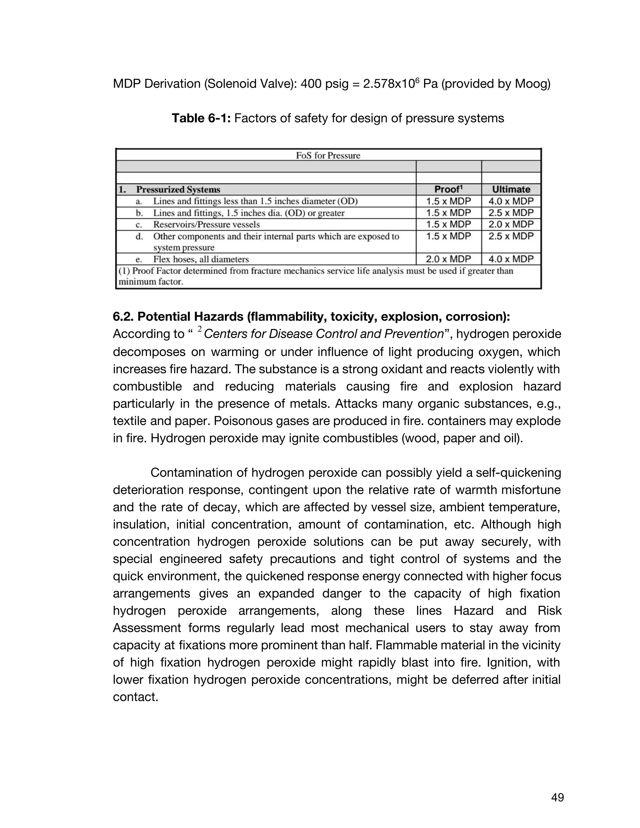
![6. Hazard Report Development (SLS Plan 217)
6.1. Summary of derivation of system MDPs
● MDP Derivation (Tanks): This derivation is presented above under the
tank section.
● MDP Derivation (Tubing):
To help determine the tank pressures, the major and minor head loss were calculated
to find the pressure drop across the propellant feed system. To start off, the volumetric
flow rate needed to be calculated by the given equation:
(E6.1) .16 m /sQ = ρ
m˙
= 1400 kg
m3
0.00302 s
kg
= 2 × 10⁻⁶ 3
Once the volumetric flow rate was found, the velocity through the propellant line was
calculated.
(E6.2) .0589V line = D2
0.1273 Q
= (0.002159m)2
0.1273[2.16×10 (m /s)]6 3
= 0 s
m
To calculate the major head loss, the friction factor must be found. To find the friction
factor we must first find the Reynold’s number. Since the Reynold’s number is well
below 2040, making the flow laminar and allowing the use of the specific equation for
finding the friction factor.
(E6.3).145Re = μ
ρV D
= 1.23 kg
m∙s
(1400 )(0.0589 )(0.002159m)kg
m3 s
m
= 0
(E6.4) 42.08f = Re
64
= 64
0.145 = 4
Now it is possible to solve for the major head loss, which is given by the following
equation:
(E6.5) ( ) ( )hL,major = f l
D 2g
V 2
Using the headloss, the pressure drop can finally be calculated.
(E6.6)P h (ρg)Δ = L,major
47](https://image.slidesharecdn.com/87b1ee2a-30ae-4766-9b34-15d003826770-160324043803/75/GT2PropulsionSystemSubmissionDocument-47-2048.jpg)


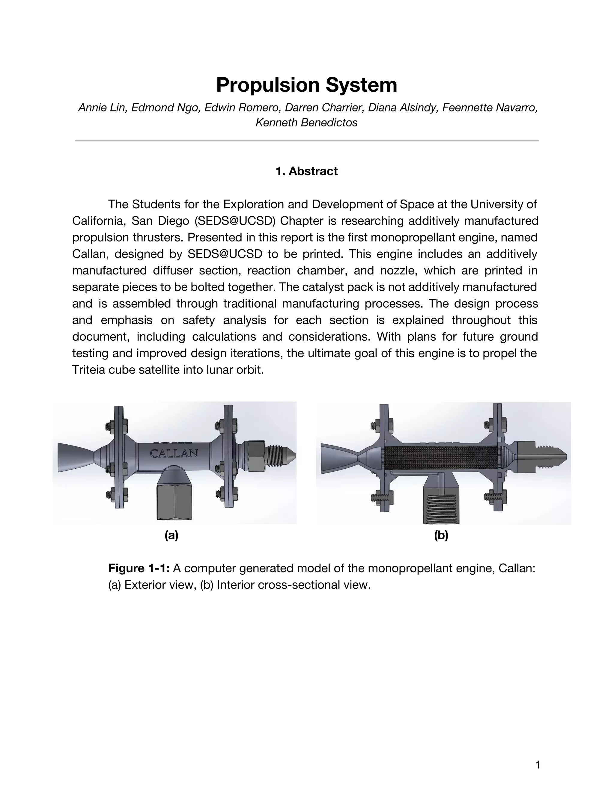
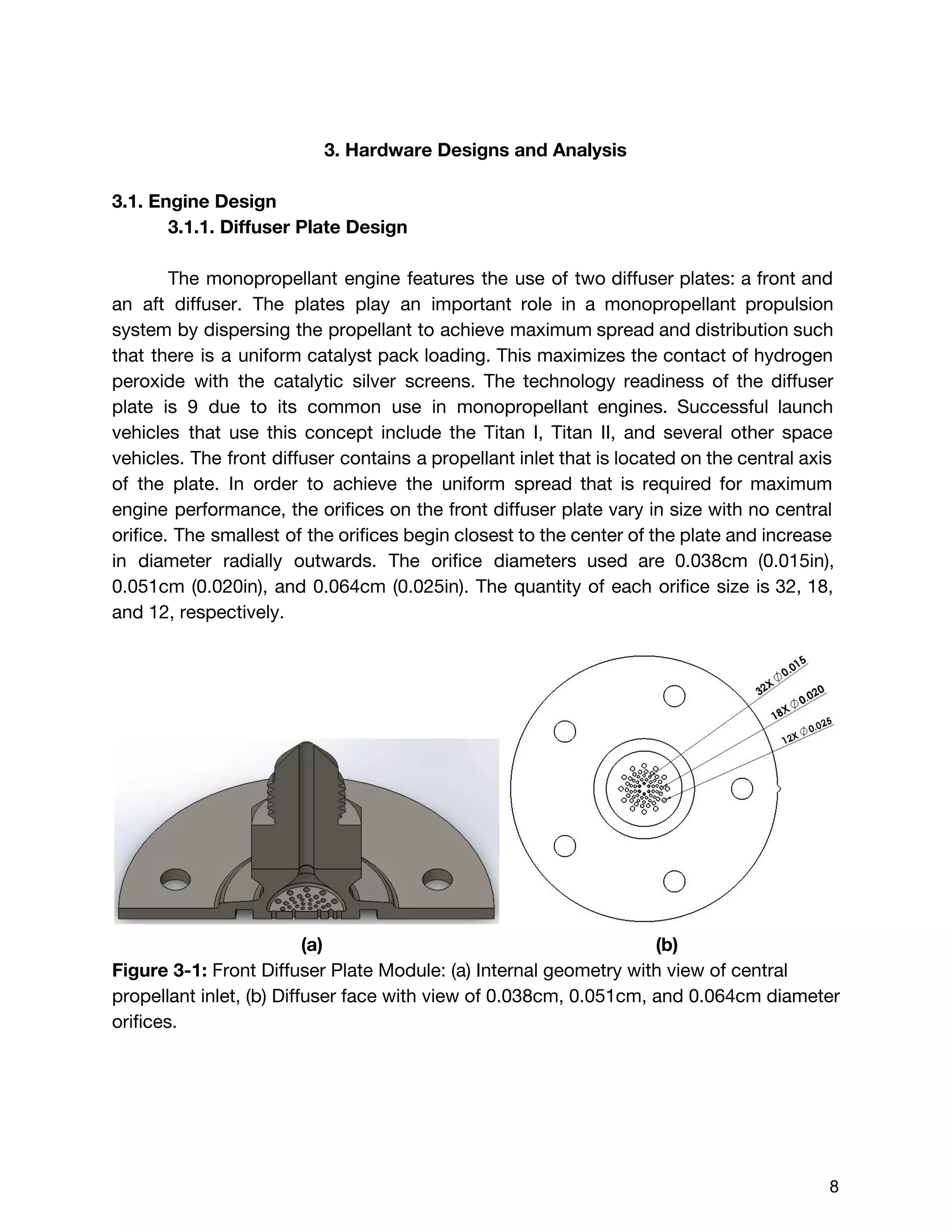
The document describes the design of a monopropellant engine named Callan being developed by SEDS@UCSD for their Triteia CubeSat mission. The engine utilizes additively manufactured components including a diffuser plate, reaction chamber, and nozzle. The diffuser plate features varying sized orifices to uniformly distribute the hydrogen peroxide propellant over the catalyst pack. Extensive analysis was performed to optimize the orifice sizing and placement. The engine and overall propulsion system for the CubeSat were designed to meet requirements for volume, safety, materials compatibility, electrical power usage, thermal, and storage conditions.