Downloaded 155 times


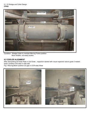

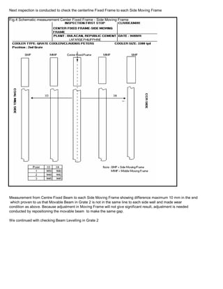


This document summarizes the inspection and alignment of a cooler with two grates. Measurements showed gaps of up to 10 mm between moving frames and side walls in the second grate, indicating misalignment. Beam levels in both grates also varied by over 1mm in places. Adjustments are recommended by adding or removing shims of up to 11 mm to realign the moving frames and level the beams.


