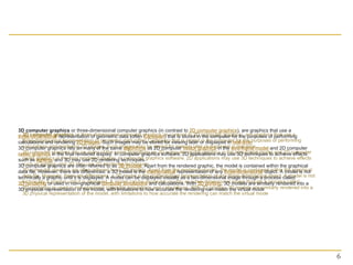
Topic 8 Geometrical Objects and
Transformations in 2D and 3D
Dr. Collins Oduor
Kenyatta University
Two Dimensional Viewing
Basic Interactive
Programming
 User controls contents,
structure, and appearance
of objects and their
displayed images via rapid
visual feedback.
D computer graphics is the computer-based generation of digital images—mostly from two-dimensional models (such as 2D geometric models, text,
and digital images) and by techniques specific to them.The word may stand for the branch of computer science that comprises such techniques or for
the models themselves.
Raster graphic sprites(left) and masks (right)
2D computer graphics are mainly used in applications that were originally developed upon traditional printing and drawing technologies, such as
typography, cartography, technical drawing, advertising, etc. In those applications, the two-dimensional image is not just a representation of a real-
world object, but an independent artifact with added semantic value; two-dimensional models are therefore preferred, because they give more direct
control of the image than 3D computer graphics (whose approach is more akin to photography than to typography).
In many domains, such as desktop publishing, engineering, and business, a description of a document based on 2D computer graphics techniques can
be much smaller than the corresponding digital image—often by a factor of 1/1000 or more. This representation is also more flexible since it can be
rendered at different resolutions to suit different output devices. For these reasons, documents and illustrations are often stored or transmitted as
2D graphic files.
2D computer graphics started in the 1950s, based on vector graphics devices. These were largely supplanted by raster-based devices in the following
decades. The PostScript language and the X Window System protocol were landmark developments in the field.
Model
 , or description designed to
show the structure or working
of an object, system, or
concept.
Benefits of 2D Animation
Since its advent in the early 1900s, it has provided a slew of benefits to animated projects. Following are just a few of the
many advantages that 2D animation provides.
Efficiency
One benefit of 2D animation is the efficiency with which it can be produced. Animation by its very nature is never a simple
process. As an art form, it requires a great deal of skill and creativity to produce objects, characters, and worlds that
appeal to the target audiences and that accurately convey stories and messages. In addition, the numerous techniques
and styles that have developed throughout the past century provide an array of tools from which the animator can
choose.
Simplicity
A second benefit of 2D animation is the fact that its designs tend to be less complex than those provided by 3D animation.
How beneficial a simpler design is depends upon the project. For instance, action films usually benefit from 3D animation
because of the detailed action and complex images they use to draw the viewer in.
However, when the design needs to highlight the message, the services of a 2D animation studio are usually preferable.
For instance, a clean design is often more effective in advertising, because it more clearly conveys the advertiser's
message to the viewer. Certain games, such as Candy Crush, also depend upon a simpler design to appeal to their
audiences. Some television shows, such as South Park, have built their success on a 2D animated design. Even some
educational applications or explainer videos require a design that will not distract the viewers from the message that the
project is trying to convey.
Cost effectiveness
The efficiency and simplicity of 2D animation lead to greater cost effectiveness, another boon to people who want the
benefits of animation but who cannot afford the sometime steep price tag that accompanies 3D animation. The fact that
this type of animation takes less time and is less complex means that it can be accomplished with fewer resources, savings
that often translate into a smaller price tag. In fact, many projects utilize 2D instead of 3D animation at least in part
because it is more cost effective for tight budgets and small companies. Any provider of 2D animation should be able to
work with your budget to create a project that meets not only your creative needs but also your financial constraints.
Artistic freedom
Each type of animation brings with it numerous creative possibilities. However, 3D animation must always appear lifelike
and realistic, no matter what scene, objects, or people it is depicting. As a result, the fanciful and exaggerated generally do
not translate well to the 3D screen, and styles such as anime are more difficult to create through the use of 3D tools.
2D animation, on the other hand, makes entirely new worlds possible. For instance, through traditional animation, the
animator can create people, animated cartoons, and more that do not exist in real life. As a result, anyone needing an
animated project can use
 2D graphics techniques[edit]
 2D graphics models may combine geometric models (also
called vector graphics), digital images (also called
raster graphics), text to be typeset (defined by content, font
style and size, color, position, and orientation), mathematical
functions and equations, and more. These components can be
modified and manipulated by two-dimensional
geometric transformations such as translation, rotation, scaling
. In object-oriented graphics, the image is described indirectly
by an object endowed with a self-rendering method—a
procedure which assigns colors to the image pixels by an
arbitrary algorithm. Complex models can be built by combining
simpler objects, in the paradigms of
object-oriented programming.
5
6
3D computer graphics or three-dimensional computer graphics (in contrast to 2D computer graphics), are graphics that use a
three-dimensional representation of geometric data (often Cartesian) that is stored in the computer for the purposes of performing
calculations and rendering 2D images. Such images may be stored for viewing later or displayed in real-time.
3D computer graphics rely on many of the same algorithms as 2D computer vector graphics in the wire-frame model and 2D computer
raster graphics in the final rendered display. In computer graphics software, 2D applications may use 3D techniques to achieve effects
such as lighting, and 3D may use 2D rendering techniques.
3D computer graphics are often referred to as 3D models. Apart from the rendered graphic, the model is contained within the graphical
data file. However, there are differences: a 3D model is the mathematical representation of any three-dimensional object. A model is not
technically a graphic until it is displayed. A model can be displayed visually as a two-dimensional image through a process called
3D rendering or used in non-graphical computer simulations and calculations. With 3D printing, 3D models are similarly rendered into a
3D physical representation of the model, with limitations to how accurate the rendering can match the virtual mode
3D computer graphics creation falls into
three basic phases
 :
 3D modeling – the process of forming a computer
model of an object's shape
 Layout and animation – the placement and movement
of objects within a scene
 3D rendering – the computer calculations that, based on
light placement, surface types, and other qualities,
generate the image
7
 Some of the advantages of 3D animation are:
 Motion communication—3D animation has a greater
and superior ability to portray movement.
 Visual appeal—3D animation is much more appealing
and realistic.
 Time is money— You can use 3D models made for a
particular project for future. It helps to lower the cost of
production.
 Good quality—3D gives high quality and more
gameplay compared to 2D.
 In demand—Most of the people now prefer 3D rather
than 2D.
8
 Fields of use
 3D data acquisition and object reconstruction
 3D motion controller
 3D projection on 2D planes
 3D reconstruction
 3D reconstruction from multiple images
 Anaglyph 3D
 Computer animation
 Computer vision
 Digital geometry
 Digital image processing
 Game development tool
 Game engine
 Geometry pipelines
 Geometry processing
 Graphics
 Isometric graphics in video games and pixel art
 Level editor
 List of stereoscopic video games
 Medical animation
 Render farm
 SIGGRAPH
 Stereoscopy
 Timeline of computer animation in film and television
 Video game graphics
9
 Some of the disadvantages are:
 Limited imagination
 Lack of simplicity.
 Profit & loss—In few cases the whole lot of effort, time
& resources spent on a 3D project may not be as
expected.
10
Modeling
 In Modeling, we often use a geometric
model
 i.e.. A description of an object that provides a
numerical description of its shape, size and
various other properties.
 Dimensions of the object are usually
given in units appropriate to the object:
 meters for a ship
 kilometres for a country
Modeling
 The shape of the object is often
described in terms of sub-parts, such as
circles, lines, polygons, or cubes.
 Example: Model of a house units are in
meters
6
9
6
y
x
6
9
y
x
 Instances of this object may then be
placed in various positions in a scene, or
world, scaled to different sizes, rotated,
or deformed.
 Each house is created with instances of
the same model, but with different
parameters.
Instances of Objects
2D Viewing
2D Viewing
Viewing is the process of
drawing a view of a
model on a
2-dimensional display.
2D Viewing
 The geometric description of the object
or scene provided by the model, is
converted into a set of graphical
primitives, which are displayed where
desired on a 2D display.
 The same abstract model may be viewed
in many different ways:
 e.g. faraway, near, looking down, looking up
Real World Coordinates
 It is logical to use dimensions which are
appropriate to the object e.g.
 meters for buildings
 nanometers or microns for molecules, cells, atoms
 light years for astronomy
 The objects are described with respect to their
actual physical size in the real world, and then
mapped
mapped onto screen
screen co-ordinates.
 It is therefore possible to view an object at
various sizes by zooming in and out, without
actually having to change the model.
2D Viewing
 How much
How much of the model should be drawn?
 Where
Where should it appear on the display?
How
How do we convert Real-world coordinates
into screen co-ordinates?
 We could have a model of a whole room, full of objects
such as chairs, tablets and students.
 We may want to view the whole room in one go, or
zoom in on one single object in the room.
 We may want to display the object or scene on the full
screen, or we may only want to display it on a portion
of the screen.
2D Viewing
 Once a model has been constructed, the
programmer can specify a view.
A 2-Dimensional view consists of two
two
rectangles:
 A Window
Window, given in real-world co-ordinates,
which defines the portion of the model that is to
be drawn
 A Viewport
Viewport given in screen co-ordinates,
which defines the portion of the screen on
which the contents of the window will be
displayed
Basic Interactive Programming
 Window
Window: What is to be viewed
 Viewport
Viewport: Where is to be displayed
Scene Image
Viewport
Coordinate
Representations
Coordinate Representations
 General graphics packages
are designed to be used with
Cartesian coordinate
specifications.
 Several different Cartesian
reference frame are used to
construct and display a scene.
Coordinate Representations
 Modeling coordinates: We can construct the
shape of individual objects in a scene within
separate coordinate reference frames called
modeling (local) coordinates.
Coordinate Representations
 World coordinates: Once individual object
shapes have been specified, we can place
the objects into appropriate positions within
the scene using reference frame called world
coordinate.
Coordinate Representations
 Device Coordinates: Finally, the world
coordinates description of the scene is
transferred to one or more output-device
reference frames for display, called device
(screen) coordinates.
Coordinate Representations
 Normalized Coordinates: A graphic system
first converts world coordinate positions to
normalized device coordinates, in the range 0 to
1.This makes the system independent of the
output-devices.
Coordinate Representations
 An initial modeling coordinate position is
transferred to a device coordinate position
with the sequence:
 The modeling and world coordinate positions in this
transformation can be any floating values;
normalized coordinates satisfy the inequalities:
 The device coordinates are integers within the range
(0,0) to for a particular output device.
1
0 
 nc
x 1
0 
 nc
y
)
,
( max
max
y
x
The Viewing Pipeline
 A world coordinate area selected for display is
called window.
 An area on a display device to which a window
is mapped a viewport.
 Windows and viewports are rectangular in
standard position.
The Viewing Pipeline
 The mapping of a part of a world coordinate
scene to device coordinate is referred to as
viewing transformation or window-to-
viewport transformation or windowing
transformation.
Viewport
window-to-viewport transformation
The Viewing Pipeline
1. Construct the scene in world coordinate using the output
primitives.
2. Obtain a particular orientation for the window by set up a two
dimensional viewing coordinate
viewing coordinate system in the world
coordinate, and define a window in the viewing coordinate
system. Transform descriptions in world coordinates to viewing
coordinates (clipping
clipping).
The Viewing Pipeline
3. Define a viewport in normalized coordinate, and map the
viewing coordinate description of the scene to normalized
coordinate
4. (All parts lie outside the viewport are clipped
clipped), and contents
of the viewport are transferred to device coordinates.
Viewing CoordinateNormalized CoordinateDevice Coordinate
1
1
The Viewing Pipeline
 By Changing the position of the viewport, we
can view objects at different position on the
display area of an output device.
The Viewing Pipeline
 By varying the size of viewport, we can change
the size of displayed objects (zooming).
2D Geometric
Transformations
2D Geometric Transformations
 Operations that are applied to the
geometric description of an object to
change its position, orientation or size.
Basic transformation:
 Translation
 Rotation
 Scaling
2D Translation
 2D Translation: Move a point along a
straight-line path to its new location.
y
x
t
y
y
t
x
x 




 ,






















y
x
t
t
y
x
y
x
T
P
P 


2D Tranlation
 Rigid-body translation: moves objects
without deformation (every point of the object
is translated by the same amount)
Note: House shifts position relative to
origin
tx = 2
ty = 3
Y
X
0
1
1
2
2
3 4 5 6 7 8 9 10
3
4
5
6






1
2






4
4
2D Rotation
 2D Rotation: Rotate the points a specified
rotation angle about the rotation axis.
 Axis is perpendicular to xy plane; specify only
rotation point (pivot point )
)
,
( r
r y
x
r
x
r
y

2D Scaling
 An positive numeric values can be assigned to the
scaling factors.
 Values less than 1 reduce the size of objects, and
greater than 1 produce an enlargement.
 Uniform Scaling:
Uniform Scaling:
 Differential Scaling:
Differential Scaling: , used in modeling
applications.
y
x
s
s 
y
x
s
s 
original Uniform scaling Differential scaling
y
x
s
s  y
x
s
s 
2D Scaling
 The matrix expression could be modified to include
fixed coordinates.
Note: House shifts position relative to
origin
Y
X
0
1
1
2
2
3 4 5 6 7 8 9 10
3
4
5
6






1
2






1
3 





2
6






2
9
2
3


y
x
s
s
)
1
(
'
x
f
x s
x
s
x
x 



)
1
(
'
y
f
y s
y
s
y
y 



Matrix Representations
And
Homogeneous Coordinates
Composite
Transformation
Transformations Between Coordinates
Systems
 It is often requires the transformation of object
description from one coordinate system to
another.
How do we transform between two
Cartesian coordinate systems?
Transformations Between Coordinates
Systems
 Two Steps:
1. Translate so that the origin (x0,y0) of the x´y´
system is moved to the origin of the xy system.
2. Rotate the x´ axis onto the x axis.
Viewing Coordinate
Reference Frame
Clipping
Clipping
Clipping
 Clipping Algorithm or Clipping: Any
procedure that identifies those portion of a
picture that are either inside or outside of a
specified region of space.
 The region against which an object is to
clipped is called a clip window
clip window.
Point Clipping
Point Clipping
(x, y)
wx2
wx1
wy1
wy2
max
min
max
min
yw
y
yw
xw
x
xw




Line Clipping
Line Clipping
 A line clipping procedure involves
several parts:
1. Determine whether line lies completely inside
the clipping window.
2. Determine whether line lies completely
outside the clipping window.
3. Perform intersection calculation with one or
more clipping boundaries.
Line Clipping
1. If the value of u is outside the range 0 to 1: The
line dose not enter the interior of the window at
that boundary.
2. If the value of u is within the range 0 to 1, the
line segment does cross into the clipping area.
 Clipping line segments with these
parametric tests requires a good deal of
computation, and faster approaches to
clipper are possible.

Geometrical Objects and Transformations in 2D and 3D Graphics.ppt

  • 1.
    Topic 8 GeometricalObjects and Transformations in 2D and 3D Dr. Collins Oduor Kenyatta University
  • 2.
    Two Dimensional Viewing BasicInteractive Programming
  • 3.
     User controlscontents, structure, and appearance of objects and their displayed images via rapid visual feedback. D computer graphics is the computer-based generation of digital images—mostly from two-dimensional models (such as 2D geometric models, text, and digital images) and by techniques specific to them.The word may stand for the branch of computer science that comprises such techniques or for the models themselves. Raster graphic sprites(left) and masks (right) 2D computer graphics are mainly used in applications that were originally developed upon traditional printing and drawing technologies, such as typography, cartography, technical drawing, advertising, etc. In those applications, the two-dimensional image is not just a representation of a real- world object, but an independent artifact with added semantic value; two-dimensional models are therefore preferred, because they give more direct control of the image than 3D computer graphics (whose approach is more akin to photography than to typography). In many domains, such as desktop publishing, engineering, and business, a description of a document based on 2D computer graphics techniques can be much smaller than the corresponding digital image—often by a factor of 1/1000 or more. This representation is also more flexible since it can be rendered at different resolutions to suit different output devices. For these reasons, documents and illustrations are often stored or transmitted as 2D graphic files. 2D computer graphics started in the 1950s, based on vector graphics devices. These were largely supplanted by raster-based devices in the following decades. The PostScript language and the X Window System protocol were landmark developments in the field.
  • 4.
    Model  , ordescription designed to show the structure or working of an object, system, or concept. Benefits of 2D Animation Since its advent in the early 1900s, it has provided a slew of benefits to animated projects. Following are just a few of the many advantages that 2D animation provides. Efficiency One benefit of 2D animation is the efficiency with which it can be produced. Animation by its very nature is never a simple process. As an art form, it requires a great deal of skill and creativity to produce objects, characters, and worlds that appeal to the target audiences and that accurately convey stories and messages. In addition, the numerous techniques and styles that have developed throughout the past century provide an array of tools from which the animator can choose. Simplicity A second benefit of 2D animation is the fact that its designs tend to be less complex than those provided by 3D animation. How beneficial a simpler design is depends upon the project. For instance, action films usually benefit from 3D animation because of the detailed action and complex images they use to draw the viewer in. However, when the design needs to highlight the message, the services of a 2D animation studio are usually preferable. For instance, a clean design is often more effective in advertising, because it more clearly conveys the advertiser's message to the viewer. Certain games, such as Candy Crush, also depend upon a simpler design to appeal to their audiences. Some television shows, such as South Park, have built their success on a 2D animated design. Even some educational applications or explainer videos require a design that will not distract the viewers from the message that the project is trying to convey. Cost effectiveness The efficiency and simplicity of 2D animation lead to greater cost effectiveness, another boon to people who want the benefits of animation but who cannot afford the sometime steep price tag that accompanies 3D animation. The fact that this type of animation takes less time and is less complex means that it can be accomplished with fewer resources, savings that often translate into a smaller price tag. In fact, many projects utilize 2D instead of 3D animation at least in part because it is more cost effective for tight budgets and small companies. Any provider of 2D animation should be able to work with your budget to create a project that meets not only your creative needs but also your financial constraints. Artistic freedom Each type of animation brings with it numerous creative possibilities. However, 3D animation must always appear lifelike and realistic, no matter what scene, objects, or people it is depicting. As a result, the fanciful and exaggerated generally do not translate well to the 3D screen, and styles such as anime are more difficult to create through the use of 3D tools. 2D animation, on the other hand, makes entirely new worlds possible. For instance, through traditional animation, the animator can create people, animated cartoons, and more that do not exist in real life. As a result, anyone needing an animated project can use
  • 5.
     2D graphicstechniques[edit]  2D graphics models may combine geometric models (also called vector graphics), digital images (also called raster graphics), text to be typeset (defined by content, font style and size, color, position, and orientation), mathematical functions and equations, and more. These components can be modified and manipulated by two-dimensional geometric transformations such as translation, rotation, scaling . In object-oriented graphics, the image is described indirectly by an object endowed with a self-rendering method—a procedure which assigns colors to the image pixels by an arbitrary algorithm. Complex models can be built by combining simpler objects, in the paradigms of object-oriented programming. 5
  • 6.
    6 3D computer graphicsor three-dimensional computer graphics (in contrast to 2D computer graphics), are graphics that use a three-dimensional representation of geometric data (often Cartesian) that is stored in the computer for the purposes of performing calculations and rendering 2D images. Such images may be stored for viewing later or displayed in real-time. 3D computer graphics rely on many of the same algorithms as 2D computer vector graphics in the wire-frame model and 2D computer raster graphics in the final rendered display. In computer graphics software, 2D applications may use 3D techniques to achieve effects such as lighting, and 3D may use 2D rendering techniques. 3D computer graphics are often referred to as 3D models. Apart from the rendered graphic, the model is contained within the graphical data file. However, there are differences: a 3D model is the mathematical representation of any three-dimensional object. A model is not technically a graphic until it is displayed. A model can be displayed visually as a two-dimensional image through a process called 3D rendering or used in non-graphical computer simulations and calculations. With 3D printing, 3D models are similarly rendered into a 3D physical representation of the model, with limitations to how accurate the rendering can match the virtual mode
  • 7.
    3D computer graphicscreation falls into three basic phases  :  3D modeling – the process of forming a computer model of an object's shape  Layout and animation – the placement and movement of objects within a scene  3D rendering – the computer calculations that, based on light placement, surface types, and other qualities, generate the image 7
  • 8.
     Some ofthe advantages of 3D animation are:  Motion communication—3D animation has a greater and superior ability to portray movement.  Visual appeal—3D animation is much more appealing and realistic.  Time is money— You can use 3D models made for a particular project for future. It helps to lower the cost of production.  Good quality—3D gives high quality and more gameplay compared to 2D.  In demand—Most of the people now prefer 3D rather than 2D. 8
  • 9.
     Fields ofuse  3D data acquisition and object reconstruction  3D motion controller  3D projection on 2D planes  3D reconstruction  3D reconstruction from multiple images  Anaglyph 3D  Computer animation  Computer vision  Digital geometry  Digital image processing  Game development tool  Game engine  Geometry pipelines  Geometry processing  Graphics  Isometric graphics in video games and pixel art  Level editor  List of stereoscopic video games  Medical animation  Render farm  SIGGRAPH  Stereoscopy  Timeline of computer animation in film and television  Video game graphics 9
  • 10.
     Some ofthe disadvantages are:  Limited imagination  Lack of simplicity.  Profit & loss—In few cases the whole lot of effort, time & resources spent on a 3D project may not be as expected. 10
  • 11.
    Modeling  In Modeling,we often use a geometric model  i.e.. A description of an object that provides a numerical description of its shape, size and various other properties.  Dimensions of the object are usually given in units appropriate to the object:  meters for a ship  kilometres for a country
  • 12.
    Modeling  The shapeof the object is often described in terms of sub-parts, such as circles, lines, polygons, or cubes.  Example: Model of a house units are in meters 6 9 6 y x
  • 13.
    6 9 y x  Instances ofthis object may then be placed in various positions in a scene, or world, scaled to different sizes, rotated, or deformed.  Each house is created with instances of the same model, but with different parameters. Instances of Objects
  • 14.
  • 15.
    2D Viewing Viewing isthe process of drawing a view of a model on a 2-dimensional display.
  • 16.
    2D Viewing  Thegeometric description of the object or scene provided by the model, is converted into a set of graphical primitives, which are displayed where desired on a 2D display.  The same abstract model may be viewed in many different ways:  e.g. faraway, near, looking down, looking up
  • 17.
    Real World Coordinates It is logical to use dimensions which are appropriate to the object e.g.  meters for buildings  nanometers or microns for molecules, cells, atoms  light years for astronomy  The objects are described with respect to their actual physical size in the real world, and then mapped mapped onto screen screen co-ordinates.  It is therefore possible to view an object at various sizes by zooming in and out, without actually having to change the model.
  • 18.
    2D Viewing  Howmuch How much of the model should be drawn?  Where Where should it appear on the display? How How do we convert Real-world coordinates into screen co-ordinates?  We could have a model of a whole room, full of objects such as chairs, tablets and students.  We may want to view the whole room in one go, or zoom in on one single object in the room.  We may want to display the object or scene on the full screen, or we may only want to display it on a portion of the screen.
  • 19.
    2D Viewing  Oncea model has been constructed, the programmer can specify a view. A 2-Dimensional view consists of two two rectangles:  A Window Window, given in real-world co-ordinates, which defines the portion of the model that is to be drawn  A Viewport Viewport given in screen co-ordinates, which defines the portion of the screen on which the contents of the window will be displayed
  • 20.
    Basic Interactive Programming Window Window: What is to be viewed  Viewport Viewport: Where is to be displayed Scene Image Viewport
  • 21.
  • 22.
    Coordinate Representations  Generalgraphics packages are designed to be used with Cartesian coordinate specifications.  Several different Cartesian reference frame are used to construct and display a scene.
  • 23.
    Coordinate Representations  Modelingcoordinates: We can construct the shape of individual objects in a scene within separate coordinate reference frames called modeling (local) coordinates.
  • 24.
    Coordinate Representations  Worldcoordinates: Once individual object shapes have been specified, we can place the objects into appropriate positions within the scene using reference frame called world coordinate.
  • 25.
    Coordinate Representations  DeviceCoordinates: Finally, the world coordinates description of the scene is transferred to one or more output-device reference frames for display, called device (screen) coordinates.
  • 26.
    Coordinate Representations  NormalizedCoordinates: A graphic system first converts world coordinate positions to normalized device coordinates, in the range 0 to 1.This makes the system independent of the output-devices.
  • 27.
    Coordinate Representations  Aninitial modeling coordinate position is transferred to a device coordinate position with the sequence:  The modeling and world coordinate positions in this transformation can be any floating values; normalized coordinates satisfy the inequalities:  The device coordinates are integers within the range (0,0) to for a particular output device. 1 0   nc x 1 0   nc y ) , ( max max y x
  • 28.
  • 29.
    The Viewing Pipeline A world coordinate area selected for display is called window.  An area on a display device to which a window is mapped a viewport.  Windows and viewports are rectangular in standard position.
  • 30.
    The Viewing Pipeline The mapping of a part of a world coordinate scene to device coordinate is referred to as viewing transformation or window-to- viewport transformation or windowing transformation. Viewport window-to-viewport transformation
  • 31.
    The Viewing Pipeline 1.Construct the scene in world coordinate using the output primitives. 2. Obtain a particular orientation for the window by set up a two dimensional viewing coordinate viewing coordinate system in the world coordinate, and define a window in the viewing coordinate system. Transform descriptions in world coordinates to viewing coordinates (clipping clipping).
  • 32.
    The Viewing Pipeline 3.Define a viewport in normalized coordinate, and map the viewing coordinate description of the scene to normalized coordinate 4. (All parts lie outside the viewport are clipped clipped), and contents of the viewport are transferred to device coordinates. Viewing CoordinateNormalized CoordinateDevice Coordinate 1 1
  • 33.
  • 34.
    The Viewing Pipeline By Changing the position of the viewport, we can view objects at different position on the display area of an output device.
  • 35.
    The Viewing Pipeline By varying the size of viewport, we can change the size of displayed objects (zooming).
  • 36.
  • 37.
    2D Geometric Transformations Operations that are applied to the geometric description of an object to change its position, orientation or size. Basic transformation:  Translation  Rotation  Scaling
  • 38.
    2D Translation  2DTranslation: Move a point along a straight-line path to its new location. y x t y y t x x       ,                       y x t t y x y x T P P   
  • 39.
    2D Tranlation  Rigid-bodytranslation: moves objects without deformation (every point of the object is translated by the same amount) Note: House shifts position relative to origin tx = 2 ty = 3 Y X 0 1 1 2 2 3 4 5 6 7 8 9 10 3 4 5 6       1 2       4 4
  • 40.
    2D Rotation  2DRotation: Rotate the points a specified rotation angle about the rotation axis.  Axis is perpendicular to xy plane; specify only rotation point (pivot point ) ) , ( r r y x r x r y 
  • 41.
    2D Scaling  Anpositive numeric values can be assigned to the scaling factors.  Values less than 1 reduce the size of objects, and greater than 1 produce an enlargement.  Uniform Scaling: Uniform Scaling:  Differential Scaling: Differential Scaling: , used in modeling applications. y x s s  y x s s  original Uniform scaling Differential scaling y x s s  y x s s 
  • 42.
    2D Scaling  Thematrix expression could be modified to include fixed coordinates. Note: House shifts position relative to origin Y X 0 1 1 2 2 3 4 5 6 7 8 9 10 3 4 5 6       1 2       1 3       2 6       2 9 2 3   y x s s ) 1 ( ' x f x s x s x x     ) 1 ( ' y f y s y s y y    
  • 43.
  • 44.
  • 45.
    Transformations Between Coordinates Systems It is often requires the transformation of object description from one coordinate system to another. How do we transform between two How do we transform between two Cartesian coordinate systems? Cartesian coordinate systems?
  • 46.
    Transformations Between Coordinates Systems Two Steps: 1. Translate so that the origin (x0,y0) of the x´y´ system is moved to the origin of the xy system. 2. Rotate the x´ axis onto the x axis.
  • 47.
  • 48.
  • 49.
  • 50.
    Clipping  Clipping Algorithmor Clipping: Any procedure that identifies those portion of a picture that are either inside or outside of a specified region of space.  The region against which an object is to clipped is called a clip window clip window.
  • 51.
  • 52.
  • 53.
  • 54.
    Line Clipping  Aline clipping procedure involves several parts: 1. Determine whether line lies completely inside the clipping window. 2. Determine whether line lies completely outside the clipping window. 3. Perform intersection calculation with one or more clipping boundaries.
  • 55.
    Line Clipping 1. Ifthe value of u is outside the range 0 to 1: The line dose not enter the interior of the window at that boundary. 2. If the value of u is within the range 0 to 1, the line segment does cross into the clipping area.  Clipping line segments with these parametric tests requires a good deal of computation, and faster approaches to clipper are possible.