Call Girls Service Nagpur Tanvi Call 7001035870 Meet With Nagpur Escorts
Generaltec power line-en
1. 8
1. Electronic Devices and Noise Issues
There are a great deal of electronic devices used in
our lives, such as mobile phones, AV devices, personal
computers, copy machines, and fax machines.
These devices are seldom free from electric noise
generation. Devices that insufficiently control noise can at
times cause trouble or large social problems.
Cases of noise issues
In a pulp factory in Yamanashi prefecture, a malfunction
occurred in the control module of the numeric control
panel, and a worker died by getting caught in the rotating
main shaft.
In a private railway station in Sakai City, Osaka
Prefecture, train radio system contact was disabled by
noise. The noises were generated by the electromagnetic
waves emitted from game machines in a video game
arcade located about 20m away.
When a patient with an implanted cardiac pacemaker
used an electric thermal medical device, the pacemaker
operation was halted.
When a mobile phone was used in a hospital, a
malfunction occurred in the syringe pump in use for a
patient.
Along with the rapid spread of devices using radio waves
and digital devices, the necessity of noise regulations
has rapidly been increasing. And now, there are various
regulations for electronic devices around the world.
Both suppressing noises generated from electronic
devices and implementing countermeasures against
the influence of noises emitted from other devices are
necessary.
We can thus say that an operating situation where both
conditions are satisfied can be called a status where “EMC
conditions are kept”.
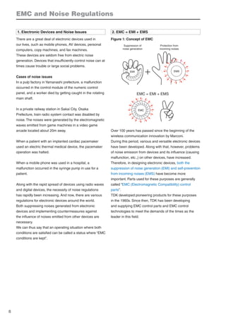
2. EMC = EMI + EMS
Figure 1: Concept of EMC
EMI EMS
EMC
EMC = EMI + EMS
Suppression of
noise generation
Protection from
incoming noises
Over 100 years has passed since the beginning of the
wireless communication innovation by Marconi.
During this period, various and versatile electronic devices
have been developed. Along with that, however, problems
of noise emission from devices and its influence (causing
malfunction, etc.,) on other devices, have increased.
Therefore, in designing electronic devices, both the
suppression of noise generation (EMI) and self-prevention
from incoming noises (EMS) have become more
important. Parts used for these purposes are generally
called “EMC (Electromagnetic Compatibility) control
parts”.
TDK developed pioneering products for these purposes
in the 1960s. Since then, TDK has been developing
and supplying EMC control parts and EMC control
technologies to meet the demands of the times as the
leader in this field.
EMC and Noise Regulations
2. 9
3. EMC Standards in the World
Various countries in the world have their own respective
EMC-related standards for development of products
which are not influenced by incoming noises or do not
have noise-related influence on other devices.
In most countries, EMC standards are established
conforming to the standards of the International Special
Committee on Radio Interference (CISPR), realizing
a comfortable life where mobile phones, personal
computers, home electric appliances, and other devices
work properly.
Figure 2: EMC standards in the world
Have you noticed one or more of these marks on electric products
or electronic devices on their back or other locations?
The CE mark is from Europe, the FCC mark is from the U.S.A.,
and the VCCI mark is from Japan.
These marks guarantee comfortable use of the product.
4. About Noises
“Noise” is defined as below in the fields of electronics /
communication / information.
“Noise” is defined as a factor that prevents proper
conveyance of intended signals (information).
The definition above is simple but abstract.
Actually, noises differ widely in their phenomena and
characteristics, etc., and it is not easy to pinpoint the true
figure of a noise.
In conveyance of signals (information), there exists a
“source point”, “reception point”, and “transfer pathway”.
The degree of influence of noise differs depending on the
various conditions in which it is found.
For example, if outgoing signals sent from a source are
strong, some noise intrusion may not have any influence
on the conveyance of signals.
If outgoing signals are weak, however, noise may have
some influence on the conveyance of signals, and the
signals may not be properly received at the reception
point.
Or, if a reception point is too sensitive, the reception point
may catch unintended signals along with the intended
signals, resulting in the occurrence of noise.
Thus, be aware that noise problems are not isolated
matters but relative matters. There are three factors as
shown below in every noise issue.
All of them definitely exist where trouble from noise
occurs. Such an issue cannot occur if even only one of
them is lacking.
Source point
Transfer
pathway Reception point
Further, the degree of trouble differs depending on the
“strength of generated energy” from the source point,
“conveyability” in the transfer pathway, and “susceptibility
to noise” at the reception point.
Accordingly, noise control involves countermeasures
against noise in these three areas. The basics are as
follows.
Source point · · · · · · Weakening generated energy
Transfer pathway · · · Reducing conveyability
Reception point · · · · Reducing susceptibility to noise
3. 10
5. Noises in our surroundings
There are two types of noise sources. One is noise
sources that occur naturally. And the other is noise
sources from artificial systems.
Naturally occurring noise sources are literally generated
by natural phenomenon, such as lightning and static
electricity.
Noise sources from artificial systems are generated by
various artificial sources.
Major noise sources from artificial systems are as follows:
“glow discharge” produced by fluorescent lights and
neon lights, transmitting signals and airwaves from fixed
stations and mobile stations in wireless communications,
mobile phones, “electronic switches” by semiconductors
in switching power supply units and inverters, pulse
generation by digital devices, “corona discharge”
produced by electric power cables, “spark discharge”
produced by cars, electric discharge machines, electric
trains, and internal combustion engines, etc.
Figure 3: Noise types
Lightning
Space discharge
(static electricity)
Cosmic rays
Magnetic storms
Earth current, etc.
• By electromagnetic energy leakage
Corona discharge produced by electric power cables
Fluorescent lights, Neon lights (glow discharge)
Switching power supply units (switching noise)
Digital devices (pulse generation)
Spark discharge produced by internal combustion engines
Electric trains (electric discharge from pantographs)
Motors (brush discharge)
High-frequency welding machines
Laser beam machine
Microwave oven
• By intentional radiation of
electromagnetic waves
Transmitting signals in
wireless communications
Airwaves
Mobile phones
Wireless LAN
Transceiver
Ham radio
Radar
Naturally occuring
noises
Noise produced
by artificial systems
6. Conduction Noises and Radiation Noises
There are two noise transfer pathways. One is cables and
printed patterns of electronic devices.
The other is the air. Noises transferred via the former are
called “conduction noises”, and noises transferred via the
latter are called “radiation noises”.
Note that noises being transferred on cables or printed
patterns can be radiated into the air along the way, and
change into radiation noises. Or, radiated noises can
intrude into cables and signal lines, and change into
conduction noises.
Noise transfer pathways are dominated by a combination
of various conditions including set composition, parts and
printed pattern design. They are complexly intertwined
with one another.
There can be a limitless number of noise transfer
pathways, and so it is very important to implement
countermeasures for these in locations close to noise
sources.
EMC and Noise Regulations
4. 11
Figure 4: Noise transfer pathways
Power
module
Transmission IC
3.3V power supply
Ground
Ground
Connector
3.3V power supply
Reception IC
Board A
Board B
Power transformer
:There is a large loop current from
the “ground of board A” to the
“ground of board B”, and then to
the “chassis”, and again to the
“ground of board A”. This is merely
one of the limitless number of
noise transfer pathways.
7.Two Conveyance routes of Conduction Noises
and Countermeasure Basics
As mentioned above, there are two types of noises,
conduction noises and radiation noises.
Conduction noises can be classified into differential mode
noises and common mode noises.
Differential mode noises are generated in power lines
and flow in the same direction as the power current
and signals. As their outward and return directions are
different, they are called differential mode noises.
Differential mode noises reside in a frequency range
higher than the signal frequency. Therefore, LPF-type
noise control parts, which reduce higher frequency
components, are used.
However, note that if the noise frequency range overlaps
the signal frequency range to be passed, signals will be
removed along with the noise.
Especially, note that removing overshoot or ringing with
noise control parts inserted in transfer pathways of
square waves can make the rise time of the square waves
longer, resulting in a reduction of IC operating margins.
It is important to recognize the frequency characteristics
of the noise control parts and the frequency range of the
signals to be passed.
Recently, operating speeds of circuits have become
faster, and the frequency ranges of signals and noises
have become closer. Therefore, it is not easy to control
noises without lowering signal quality.
Common mode noises flow to SG in the same direction
as signal patterns, pass through metal frames or metal
cases and stray capacitors, etc., and return to signal
sources. As their flow direction is common, they are called
common mode noises.
Figure 5: Differential mode noises and Common mode
noises
Signal source
Differential mode noises
Differential mode
Common mode
Noise current
Signal current
Electroniccircuit
Board
Metal frame
(chassis)
Common mode
noise current
Signal current
Board
SG
SG
FG
Electroniccircuit
Stray capacitance
between signal
line and metal
frame
Signal
source
Differential mode noises are components that flow within
relatively narrow circuits, and their outward and return
directions are opposite. Therefore, noise components
cancel each other out and become reduced, and radiation
noises become smaller.
Common mode noises pass through metal frames or
metal cases, etc., away from signal lines, and return.
Therefore, common mode noises form large current loops
5. 12
and even small noise currents radiate large noises. In
controlling radiation noises, controlling common mode
noises is more important.
8. Countermeasure Basics for Conduction Noises
Conduction noises are transferred through signal lines
such as printed patterns and cables, along with signals.
Therefore, noise control parts should be set in a location
as close to the noise source as possible along the same
path as signal lines to remove only noise components.
Figure 6 shows the four methods of noise reduction.
They are called “four countermeasure factors against
noise”.
(1) Shielding of the device
(2) Reflection to return only noise components to the
noise source side
(3) Absorption to convert noise components into heat
by noise control parts
(4) Bypassing to direct noises to the ground
Basic policy common to these methods is to transfer
only the necessary signals to the load sides. Conduction
noises are not only transferred through signal patterns but
also can be radiated into the air along the way, causing
noises to be received in an unexpected location, resulting
in noise related problems.
Conduction noises can often be converted into radiation
noises in locations where cables or other parts, which
function as antennas, exist. Any countermeasures
for conduction noises have the effect of serving as a
countermeasure for radiation noises at the same time.
9. Classification of Noise Control Parts
There are two types of noise control methods using
electronic parts.
One is to reduce the amount of noise generated in the
parts themselves. The other is to suppress noises that
have already been emitted by using noise control parts.
The important thing is to be aware that the noise control
parts that should be used differ depending on the noise
type, i.e., common mode noise or differential mode noise,
as shown in Figure 7.
Failure to detect the noise conduction mode or failure
to select appropriate noise control parts can cause
conditions where “noises have increased opposite to
expectation after adding a noise control part”.
Figure 6: Noise transfer and countermeasure basics
SG
Shielding
(countermeasure (1))
Shielding
(countermeasure (1))
Reflection
(countermeasure (2))
Conduction
noises
Reduced noises
Bypassing
(countermeasure (4))
Transmission
side circuit block
Noise control parts
for differential mode
Noise control
parts for
common mode
Reception side
circuit block
Absorption and conversion into heat energy
(countermeasure (3))
FG FG
SG
Surface with stable electric potential (frame ground)
EMC and Noise Regulations
6. 13
10. Noise Control Procedures and EMC Cost
EMC measures tend to be neglected in the development
of a device. It is often the case that EMC problems are
recognized for the first time in an EMC test during the last
stage of development.
However, available options for EMC measures will always
decrease as the development stage of a device proceeds,
beginning with design, and then proceeding to prototype,
and finally going to mass production.
If EMC measures are completely neglected in the
development of a device, EMC problems will occur in
almost every case.
EMC measures during later stages of development can
take a lot of time, as well as additional parts and costs,
resulting in an increase of size and weight of the device,
and an increase of power loss.
Figure 8: Relationship between device development
stage and EMC cost
Available choices for EMC measures
Design Prototype test Mass production
Cost of EMC measures
Available options for EMC measures decrease and the
cost increases as the development stage of a device
proceeds. In general, the earlier EMC measures are
taken, the better the results are, and the lower the cost is.
For on-board
Electric wave absorption sheet (gasket)
Electric wave absorbing material
Bead
Three-terminal filter
Inductor
Capacitor
Low-ESL capacitor
Common mode filter
for EMC filter
Varistor
Ferrite bead
Choke coil
Capacitor
Ferrite core
Capacitor
Line filter
Ferrite core
Ferrite core
Clamp filter
Ferrite core
For countermeasures
against static electricity
For AC power supply
For cables
For connector ICs
For shielding
For absorption of
electric waves
Noise control
parts
Differential mode
Common mode
For AC power supply
Common mode
Differential mode
Figure 7:Types of noise control parts and their usage
7. 14
EMC Filters to Suppress Incoming/Outgoing Noises to/from Power Lines
1. About Power Supply Line Noises
Electric devices operated by an AC power supply are
connected to a common power supply line. Under these
conditions, a device can be affected by noises generated
by other devices and malfunctions can occur. On the
other hand, noises generated by the device itself can
affect other devices, causing them to malfunction.
The AC power supply units of devices are inlets of
incoming noise energy, and as well as outlets of outgoing
noises generated by the respective devices. By attaching
power supply EMC filters to these inlets/outlets, incoming
noises from the outside and outgoing noises from the
power supply lines can be reduced.
Many countries in the world have their own respective
regulations about immunity levels for incoming noises and
allowable level of outgoing noises. A power supply EMC
filter is also used to meet these regulations.
Figure 9:Types of noise control parts and their usage
Inverter control device
Robot B
Robot A
Single phase
Single phase
Three phases
Noises generated by each device are transferred via AC power
supply lines.
2. Noise Types
In AC power supply lines various types of noises are
superimposed. Noises can be classified into three types,
by the voltage level and the rise time, as shown in Figure
10.
Figure 10:Types of power supply line noises
Voltage level
Rise time
Energy
- several V
---
several mJ
High-frequency noise
- several kV
1ns or less
several 100mJ
Pulse noise
- several 10kV
Surge noise
0.5µs or less
several J - several kJ
Waveform
(1) High-frequency noises
Mainly due to harmonic components in the switching
frequency in computers and switching power supply units.
Generally, EMI noise indicates this type of noise, and
common filters are designed for high-frequency noises.
Voltage levels are relatively low, i.e., several mV to several
10mV.
(2) Pulse noises
Noises generated during switching of relays and induction
motors. They are high in voltage, with peak voltage
reaching several thousand V.
They carry a larger amount of energy compared to
high-frequency noises, and can cause filter cores to be
saturated. For this reason, an amorphous magnetic core
or other core materials with a high saturation magnetic
flux density are used (refer to “High-voltage pulse
attenuation characteristic”).
(3) Surge noises
Noises generated in power supply lines due to induced
lightning, etc. They carry a large amount of energy with
very high voltage and large current. Peak voltage can
reach several 10kV.
As their energy levels are very high, surge-
countermeasure components such as varistors and
arresters are used.
8. 15
3. Safety Standards that EMC Filters for Power Supply
Lines should Meet
Power supply EMC filters are connected to the primary
side of an electronic device. Therefore, the highest level
of safety against accidental electric shock, smoking, and
firing is required. Many countries in the world have their
own safety standards as shown in Table 1. Filters should
be selected based on what is approved by the safety
standards of the countries to which the device will be
exported.
Table 1: Safety standards in countries of the world
Name of country
U.S.A.
Canada
Germany
Norway
Sweden
Finland
Denmark
Switzerland
Japan
Name of authorizing
organization(s)
UL
CSA
VDE/TÜV
NEMKO
SEMKO
FIMKO
DEMKO
SEV
Name of standard(s)
UL1283
CSA
C22.2 No.8
EN60939
Japan Electrical
Safety Environment
Technology Laboratories
Electrical Appliance
and Material Safety
Law
4. Conduction Noise Assessment Method
As explained above, outgoing noises from devices are
transferred via AC power supply lines, and intrude into
other devices, causing malfunctions or a decrease in
performance.
It is very important to reduce these noises transferred via
AC lines. An AC line noise assessment method based
on IEC noise regulations CISPR and a noise reduction
method will be explained below.
(1) Measurement method regulated by European
standards
European noise regulations EN is established based on
CISPR.
IEC noise regulations CISPR (Comite International
Special des Perturbations Radioelectriques) designates
the method for measuring conduction noises being output
via power cables for electronic devices, as well as their
allowable levels. Figure 11 shows the measurement
method designated in these regulations.
The device being measured is set on a wooden desk.
A power cable is connected to a device for noise
measurement called a LISN (Photo 1), which is located
80cm away from the device being measured.
The LISN is placed on a large conductor side (ground).
A disturbing wave measurement device checks the noise
output from the LISN and indicates its level.
Figure 11: Conduction noise measurement method
Device being
measured
For tabletop device being
measured, place it at 80cm
in height
LISN
Wave receiver of
disturbing wave
measurement device
Keep a distance of 40cm or
more from the conductor
side as the basis
Bind up power cable so that it is
40cm or shorter in length
Distance between
device being
measured and
LISN: 80cm
AC
power supply
Conductor side as the basis
Photo 1: LISN external view
Power supply outlet
(single-phase input) on rear side
For single-phase
device being measured
(to EUT)
To spectrum
analyzer
Line-switching knob
(Va/Vb)
(2) Structure of LISN
A LISN (Line Impedance Stabilizing Network) is a tool
enabling a quantitative assessment of noise levels being
output via power cables for electronic devices.
Figure 12 shows the internal circuitry of a LISN.
The internal circuitry of the LISN is a filter circuit
composed of resistors, inductors, and capacitors. The
LISN maintains a constant impedance of 50Ω for devices
being measured in a measurement frequency range
(0.15 to 30MHz), in order to measure the disturbing
wave voltages under the same conditions even if the
impedance of the power supply side differs. The two
essential functions of the LISN will be explained below.
9. 16
Figure 12 Example of the internal circuitry of a LISN
LISN
E
Voltage line
L1
Neutral line
L2
Device being
measured
Grounding
cable
Receiver
1µ 1µ
0.1µ 0.1µ
1kΩ
50µH
50µH
50Ω
50Ω
1kΩ
Dummy load
(1) Maintaining a constant impedance of 50Ω between the
voltage line conductor and grounding cable, and between
the neutral line conductor and grounding cable
(2) Preventing the intrusion of conduction noises outside
from the power supply
As shown in Figure 13 (a), the conduction noise level
can be found by measuring the voltage drop at both ends
of the resistor for noise measurement. This amount of
voltage drop equals the noise voltage between the power
supply lines and the ground (called the voltage between
one line and ground), and this is the resulting value of
combining common mode noises and differential mode
noises. This conduction noise level is generally called the
mains terminal voltage, and the unit used is “dBμV”.
Figure 13: Conduction noise measurement methods
using standard type (type V) and
conduction-mode separation type (type ⊿ )
LISNs, and noise flow
(a) Standard noise measurement circuit (type V)
(b) Conduction-mode separated measurement circuit (type ⊿)
LISN
RN1
RN2
L1
L2
Power supply EMC filter
CX1
CY1
CX2 CY2
Stray capacitance between
device and ground
FG
E
Switching power
supply module
RN1
RN1
Stray capacitance between
device and ground
E
Switching power
supply module
Resistor for measurement of differential mode current
For measurement of common mode noise current
Switching
LISN
L1
L2
Power supply EMC filter
CX1
CY1
CX2 CY2
FG
: Main conveyance routes of differential mode noise current
: Main conveyance routes of common mode noise current
(3) Separate measurement of common mode and
differential mode
Noises being output via power supplies can be classified
into differential mode noises and common mode noises.
And their noise control methods differ respectively.
A standard LISN cannot separate these two modes.
However, a LISN type such as in Figure 13 (b) can do so.
The LISN type in Figure 13 (a) is called a “type V, and
it is the standard LISN designated by CISPR and FCC
(Federal Communications Commission). Generally the
term LISN indicates this type.
The LISN type in Figure 13 (b) is called a “type ⊿ .
In the past, this type was used for measurement of
conduction noises from TV sets, etc. However, nowadays
this has rarely been used since CISPR and FCC, etc.
designated “type V” as the standard LISN. Still, “type
⊿ is the only LISN that can measure common mode
and differential mode noises separately, and it is a very
convenient tool for noise control.
5. Examples of Noise Countermeasures in Separated
Conduction Modes
(1) Example of power supply terminal measurement in
separated conduction modes
Figure 14 and figure 15 show examples of measuring the
power supply terminal voltage of a switching power supply
module, by using “type V” and “type ⊿ LISNs.
As shown in Figure 15, the “type ⊿ LISN can measure
common mode and differential mode noises separately.
Figure 15 indicates that common mode noises make up
the major proportion of noises, and countermeasures
against common mode noises should be taken first.
Figure 14: Switching power supply module conduction
noise spectrum measured by the “type V”
LISN
Radiationnoiselevel(dBµV)
120
100
80
60
40
20
0
0.15 1 5 10 30
Noise voltage spectrum
between L1 - ground
Frequency (MHz)
Line of regulation: BCISPR 22-B
EMC Filters to Suppress Incoming/Outgoing Noises to/from Power Lines
10. 17
Figure 15: Switching power supply module conduction
noise spectrum measured by the “type ⊿ ”
LISN
Noise voltage spectrum
between L1 - L2
⊿-terminalvoltage(dBµV)
120
100
80
60
40
20
0
0.15 1 5 10 30
Frequency (MHz)
(a) Measurement of differential mode noises
Noise voltage spectrum
between L1L2 - ground
⊿-terminalvoltage(dBµV)
120
100
80
60
40
20
0
0.15 1 5 10 30
Frequency (MHz)
(b) Measurement of common mode noises
(2) Countermeasures and noise reduction effects
(a) Countermeasures against common mode noises
Figure 16 shows the conditions before countermeasures
are taken. The level of common mode noises is high,
approximately 100dBμV, exceeding the allowable
regulated level by over 40dBμV.
As a countermeasure, as shown in Figure 17 (a), a
common mode filter was inserted in the AC line, and
4700pF capacitors were inserted between each line and
the frame ground (FG). The latter capacitor is called “Y”
capacitor.
Consequently, common mode noises have been reduced
to a level meeting regulations.
Figure 16: Switching power supply module conduction
noise spectrum before countermeasures
are taken
Noiseterminalvoltage(dBµV)
120
100
80
60
40
20
0
0.15 1 5 10 30
Frequency (MHz)
Common mode noises
Differential mode noises
Figure 17: Countermeasures against common mode
noises and their effects
FG
5mH CY
CY
4700pF
4700pF
(a) Inserting a common mode filter and two “Y” capacitors⊿-terminalvoltage(dBµV)
120
100
80
60
40
20
0
0.15 1 5 10 30
Frequency (MHz)
Common mode noises
Differential mode noises
(b) ⊿- terminal voltage spectrum
“Y” capacitor
Common mode
filter
(b) Countermeasures against differential mode noises
Figure 17 (b) shows the conditions before
countermeasures are taken. The 150kHz to 2MHz range
differential mode noise levels exceed the allowable
regulated level.
As a countermeasure, as shown in Figure 18 (a), 0.47μF
capacitors were inserted between AC lines. This capacitor
is called “X” capacitor.
Consequently, noises have been reduced to a level
meeting regulations.
11. 18
Figure 18: Countermeasures against differential mode
noises and their effects
FG
5mH CY
CX1
CY
4700pF
4700pF
(a) Inserting two “Y” capacitors between lines
0.47µF
CX2
0.47µF
⊿-terminalvoltage(dBµV)
120
100
80
60
40
20
0
0.15 1 5 10 30
Frequency (MHz)
Common mode noises
Differential mode noises
(b) ⊿- Mains terminal voltage spectrum
“X” capacitor
6. Selection of Noise Control Parts
Figure 19 shows a typical filter structure. A common
mode choke coil has several to several 10μH of leakage
inductance. When this component is overly used, the
core easily becomes saturated. However, this component
has an effect of reducing differential mode noises. Thus
saturation control and control of differential mode noises
are in a “trade-off” relationship.
Figure 19:Typical structure of power supply EMC
filters
(1) “Y” capacitor
A “Y” capacitor to be connected between AC lines and the
FG has an effect of emitting common mode current to the
FG.
Leak current corresponding in frequency and voltage to
the AC power supply flows in the “Y” capacitor.
As the capacity of a “Y” capacitor grows, leak current also
increases. This can cause electric shock. Therefore, UL
and other safety standards restrict the capacity so that the
amount of leak current does not exceed a certain level.
Usually, two “Y” capacitors are used, as shown in Figure
17 and Figure 18. As AC lines are connected with
capacitors, they are effective in reducing differential mode
noises. In particular, they are effective for high frequency
ranges of 8 to 10MHz or so.
(2) “X” capacitor
An “X” capacitor to be connected between AC lines is
only effective in reducing differential mode noises. It is
often called a differential mode capacitor, and one with a
relatively high capacity of 1μF or so is used.
An “X” capacitor is connected between lines. As it is not
connected between lines and the ground, there is no risk
of electric shock, etc., even if it is damaged.
An “X” capacitor is particularly effective for a frequency
range between 150kHz to 1MHz, lower than that for the “Y”
capacitor.
Figure 20: Equivalent circuit for noise filter
2CY
CY
CX1 CX2
2
+
Lleak
Lleak
(a) Equivalent circuit for
differential mode signals
(b) Equivalent circuit for
common mode signals
L
Cx R
L1
L2
L2
Cx
Cy
Cy
Cx: “X” capacitor
L1 : Common mode choke coil
L2 : Differential mode inductance
(Usually L1 leakage inductance components are utilized.)
Cy: “Y” capacitor
EMC Filters to Suppress Incoming/Outgoing Noises to/from Power Lines
12. 19
7. Filter Specifications / Characteristics
(1) Rated voltage
This is the maximum AC line voltage (actual value)
allowable within a designated operating temperature
range. Rated voltage of AC.250V is common recently, but
sometimes a rated voltage of AC.400V is also used.
As for transmission and distribution wiring systems, the
major systems in use are single-phase systems and
three-phase systems.
(2) Rated current
This is the maximum load current amount (actual value)
allowable within a designated operating temperature
range. This differs depending on the heat resistance
properties of the internal components.
Also, when used in a high ambient temperature, the
allowable load current amount should be derated
accordingly, as shown in Figure 21.
In this example, when used in an ambient temperature
of 70°C, the amount of allowable load current should be
derated to approximately 70% of the rated current.
Figure 21: Example of derating based on the ambient
temperature for a noise filter
120
100
80
60
40
20
0
Outputpower(%)
–25 –10 0 10 20 30 40 50 60 70 80 90
Ambient temperature Ta (°C)
(3) Power supply frequency
Power supply voltage frequency is generally 50Hz/60Hz.
However, a larger value is sometimes used for special
use products. For example, it is 400Hz in the aviation-
related field. Power supply EMC filters are designed for
use in 50Hz/60Hz commercial power supplies.
(4) Test voltage (withstanding voltage)
In order to simulate possible accidents including
grounding faults, tests are executed by applying several
times higher voltage than the rated voltage between lines,
or between the line and case (ground), and checking if
any failure occurs or not. This is called the withstanding
voltage test. The test voltage is that applied in the tests.
It is usually AC.1500V, AC.2000V or AC.2500V for
commercial products.
(5) Insulation resistance
This is a resistance value representing insulation strength.
This resistance value is found by applying DC voltage
between lines or between the line and case (ground),
and measuring a very small amount of current flowing in
the dielectric body of a capacitor or insulating materials
(especially in plastic cases). Applied voltage is usually
DC.500V.
(6) Leak current
Leak current is the current leaking from power supply
lines to cases (ground), when noise filters are inserted
in power supply lines and a rated voltage is applied. This
value is mainly dominated by electrostatic capacitance
(C), power supply voltage (E), and power supply voltage
frequency (f), and found in the expression below.
Leak voltage = 2πfCE
If this value is large and noise filters or ground terminals
are ungrounded, electric shock can occur.
Figure 22:Transfer pathways of leak current
Frame
Ground
Noise filter (ungrounded)
(7) DC resistance
DC resistance is the summation of resistance in a noise
filter. Almost all of this is the wire wound resistance of
the coil, but also includes resistance from the connection
to the terminal. The value calculated by multiplying DC
resistance by the load current corresponds to the voltage
drop value generated in the noise filter.
(8) Temperature rise
This is the temperature rise of a case surface when a
rated current is passed through a noise filter. In general,
this value is the one measured in a condition where a
product is directly exposed to the air. When the product is
attached to a metal board or forcibly cooled by fans, etc.,
the value will be lowered.
13. 20
(9) Attenuation characteristics (static characteristics)
This is reference to assess the attenuation characteristics
of noise filters. Data is plotted on a graph with frequency
on the horizontal axis and attenuation amount on the
vertical axis. Figure 23 shows the measurement method,
and Figure 24 shows an example of the characteristics.
Figure 23: Method of measuring attenuation
characteristics (static characteristics)
T.G.
Balun Balun
Noise
filter
S.A.
Attenuation =20Log10−(dB)
e2
e1
e1: Level when noise filter is connected
e2: Level when noise filter is not connected
* Balun is for stabilizing impedance in a specific frequency range.
* e1 and e2 are values measured in S.A.
Figure 24: Example of attenuation characteristics
0
20
40
60
80
100
0.05 0.1 0.3 0.5 1 3 5 10 30
: Normal mode
: Common mode
Attenuation(dB)
Frequency (MHz)
Here, a 20dB attenuation indicates that the noise level is reduced to 1/10, a
40dB attenuation indicates that the noise level is reduced to 1/100, and a
60dB attenuation indicates that the noise level is reduced to 1/1000.
(10) High-voltage pulse attenuation characteristics
A several kV voltage surge can occur in a power supply
line, and it can intrude into devices in the form of common
mode noises, causing them to malfunction.
For this reason pulse energy durability is assessed by
pulse-applying tests, etc., for robots and other machines.
Noise filters are used as countermeasure parts. For
countermeasures against pulse noises there is a need to
be careful of a reduced effect due to a saturation of the
magnetic materials.
Generally, the expression in Figure 25 (a) is applicable
for pulse voltage in an area where the core is not
magnetically saturated. In order to reduce the surge
voltage with a large value of multiplication of E andτ,
the saturation magnetic flux density of the core should be
higher, if the core shapes and the number of turns of coil
are the same. For this purpose an amorphous magnetic
core, which has high saturation magnetic flux density,
high permeability, and superior frequency characteristics,
is used.
Figure 25: Characteristics of amorphous magnetic
core and high-voltage pulse characteristics
B
ΔB
H
Br
Bm
OutputvoltageVout(V)
Input voltage Vin (kV)
(d) Comparison of pulse attenuation characteristics
0 0.5 1 1.5 2
300
250
200
150
100
50
0
Shape of core
Inner diameter: 22mm
Outer diameter: 38mm
Height: 13mm
Number of turns: 24mm
Ferrite
magnetic core
Amorphous
magnetic core
50Ω
50Ω
50Ω
50Ω
Vin
Noise
simulator Vout
Input pulse
waveform
Output pulse
waveform
1µs
Powersupply
EMCfilter
(c) Measurement circuit
(b) B-H characteristics (hysteresis loop)
(a) Core material characteristics and pulse voltage
ΔB=−×104E・τ
N・Ae
ΔB : Magnetic flux density change of core = Bm - Br
E : Pulse voltage Ae : Cross-section area of core
N : Number of turns of coil τ: Pulse width (sec)
Bm : Saturation magnetic flux density
Br : Residual magnetic flux density
Amorphous magnetic
core
Ferrite magnetic core
EMC Filters to Suppress Incoming/Outgoing Noises to/from Power Lines
14. 21
8. Practical Examples of Countermeasures
against Noises
(1) Countermeasures against noises in NC machine
tools
NC machine tools, which are driven by servomotors,
generate a very large amount of noises. Over 100dBμV
noises were generated by this machine tool before
countermeasures were taken. However, through the use
of filters the noises have been reduced to a level meeting
regulations.
Figure 26: Countermeasure by using a three-phase
noise filter
EUT LISN
Filter box
Ground
Filter to suppress
incoming noises
3 400V
Filter circuit
100
90
80
70
60
50
40
30
20
10
0
0.1 1 10 30
Radiationnoiselevel(dBµV)
Without noise filters
With noise filters
Frequency (MHz)
(2) Improvement of cable layout
Input and output cables of a filter were located close to
each other, causing noises from the output side to intrude
into the input side of the filter. However, by relocating the
breaker to increase the distance between the input and
output lines of the filter, noises have been reduced to a
level meeting regulations.
Figure 27: Improvement of cable layout
Breaker
Breaker
Filter
Filter
80
70
60
50
40
30
0.1 1 10 30
Frequency (MHz)
Radiationnoiselevel(dBµV)
OutputsideOutputside
InputsideInputside
Noises do not flow into
the filter because the
input and output power
cables are located
close to each other,
and the noises bypass
the filter.
The breaker has been
relocated to the left to
secure a distance
between the input and
output cables.
After countermeasures
were taken
Before countermeasures
were taken
15. 22
(3) Countermeasure by improving grounding
Since the filters are located away from the EUT main unit,
the grounding condition was not good, and the level of
high-frequency noises was high.
By improving grounding of the transformer box where
filters are set, and by improving grounding of the EUT
main unit, the noise levels have been reduced to a level
meeting standards (lowering impedance between the
transformer box and the EUT main unit by special metal-
shielded wiring).
Figure 28: Improving grounding
EUT
Transformer box
(filters are set)
100
90
80
70
60
50
40
30
20
10
0
0.1 1 10 30
Frequency (MHz)
Radiationnoiselevel(dBµV)
Before countermeasures
were taken
After countermeasures
were taken
(4) Countermeasure against saturation by filter with
amorphous magnetic core
As a large amount of current flows in a device
momentarily, the filter core was saturated and the
attenuation characteristics of the filter were weakened.
As a result, noise levels exceeded the allowable regulated
level.
By using an amorphous magnetic core, DC superimposition
characteristics have been improved, and noise levels
have been reduced to a level meeting standards (Figure
29).
Figure 29: Countermeasure against saturation of core
1.20
1.00
0.80
0.60
0.40
0.20
0.00
0 100 200 300
100
90
80
70
60
50
40
30
0.1 1 10 30
Frequency (MHz)
Radiationnoiselevel(dBµV)
Filter for countermeasure
(amorphous magnetic core type)
AC.50A standard filter
(ferrite magnetic core type)
Current (A)
Impedance(mH)
Before countermeasures
were taken
After countermeasures
were taken
EMC Filters to Suppress Incoming/Outgoing Noises to/from Power Lines
16. 23
9. Effective Filter Mounting
Noise filters are widely used for reduction of noises
outgoing/incoming to/from power supply lines. However,
if they are used incorrectly their characteristics cannot be
effective, resulting in wasted countermeasures.
Explained below are the necessary and basic matters
to be considered when using noise filters. They are also
thoroughly described in catalogs, etc., for every noise
filter manufacturer. However, it has been found that these
matters do not seem to be observed in actual devices.
This may be due to a lower incidence of noise-related
problems. However, if any problems occur after products
are released to the market, it is difficult to reproduce the
same situation, difficult to find the causes, and difficult to
find effective countermeasures.
Therefore, to assure maximum reliability of products, we
recommend checking and observing all the points for
countermeasures against noises explained below.
Countermeasure 1:
Use noise filters. Shield the device and noise sources.
Noise source Shielding
Device
Noise filter
A.C.
Countermeasure 2:
Locate units and cables away from noise sources.
A.C.
Noise source
Keep away from noise source
Countermeasure 3:
Do not allow noise current to flow in the chassis.
A.C.
A.C.
Noise current
Countermeasure 4:
Make current loops smaller.
A.C.
A.C.
Loop
Twisting
Countermeasure 5:
Be sure to locate the input and output lines away from
each other.
Input line
Output lineNoise
The input and output lines are located close to each other
Relocate the input and output lines away from each other
Noise filter
Input line Output lineNoise filter
17. 24
Countermeasure 6:
Supply power from the noise filter output side for
every unit.
A.C.
A.C.
Fan
Fan
Noise
Noise filter
Noise filter
Spread out lines
from the noise filter
output side
As short
as possible
Output
side
Output side
Countermeasure 7:
Ground wire from the noise filter should be as thick
and as short as possible.
Output lineNoise filter
Input line Output lineNoise filter
Metal case
Attaching directly to chassis of device
Ground wire should be as short as possible
Input line
Wiring thick and short
If the ground wire from the noise filter is long, inductance
increases between the noise filter and chassis causing
deterioration of the high frequency characteristics of the
noise filter. When a noise filter is grounded via a metal
case, attach the noise filter directly to the chassis of the
device after removing any coating on the contact surfaces
for better metal contact.
If a case is made of metal but not grounded, or if it is
plastic, use a lead wire as short as possible in length to
ground the noise filter via the chassis of the device.
Figure 30: Difference of attenuation effect by length
of ground wire (mains terminal voltage of
switching power supply)
L=0cm
L=10cm
L=20cm
EMC Filters to Suppress Incoming/Outgoing Noises to/from Power Lines