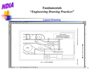
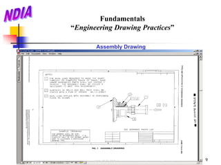
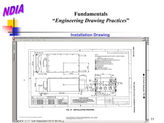
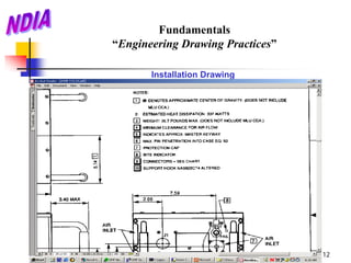
This document defines and describes the types of engineering drawings most commonly used to establish engineering requirements, including layout drawings, detail drawings, assembly drawings, installation drawings, and modifying drawings. It provides examples and explanations of when each type of drawing would be used. The key types are layout drawings for conceptual designs, detail drawings for individual parts, assembly drawings for groups of related parts, and installation drawings with details for positioning items.
Creo Parametric offers powerful 3D modeling tools that accelerate product design. This document provides an introduction to Creo Parametric and demonstrates how to perform common modeling tasks. It begins with an overview of Creo Parametric's main features and benefits. Next, it explains how to start Creo Parametric and access files from a PDM/PLM server. The document then demonstrates how to model a simple corner cube part using extrude and revolve features. It also describes how to use pattern, edit, and assembly tools in Creo Parametric.
3 Strategies for Robust Modeling in Creo ParametricEvan Winter
This document provides 3 strategies for creating robust Creo Parametric models:
1) Build smart features using intent references, publishing geometry before copy features, and creating component interfaces to simplify assembly.
2) Identify features through naming, annotations, and grouping to organize the model tree.
3) Modularize models by keeping sketches simple, externalizing rounds and chamfers, and separating features by function.
IRJET- Review on Computer Aided Fixtre DesignIRJET Journal
This document summarizes a review on computer-aided fixture design. It discusses how fixtures play an important role in manufacturing to achieve interchangeability and accuracy. Traditionally, fixture design was done through trial and error, which was time-consuming. Computer-aided fixture design (CAFD) automates the process and allows designers to simulate virtual fixtures to identify deficiencies quicker. The document outlines the main steps in CAFD as setup planning, fixture planning, unit design, and verification. It also discusses various approaches researchers have proposed for setup planning and fixture optimization.
Engineering drawings are a graphical means of communicating technical details and specifications without language barriers. They allow engineers to visualize and understand complex objects, structures, machines and their components. Drawings use standardized conventions, symbols and techniques to represent views, dimensions, materials, scales and other technical information precisely. They serve as roadmaps for manufacturing complex products. Manual drafting skills are still important for learning fundamental principles, even as computer-aided design has streamlined the process.
An assembly drawing displays the parts of a machine assembled in their working positions. It must satisfy manufacturing, operational, and maintenance requirements. There are several types of assembly drawings prepared at different stages: designed, layout, installation, working, and general. When preparing assembly drawings, important views and sections should show all parts and locations clearly. Dimensions and dotted lines are used appropriately. Each part is numbered and listed in a bill of materials with information like material, quantity, and company. The process of preparing assembly drawings involves studying component functions, geometry, dimensions, and their assembly relationships.
This document discusses computer aided design (CAD) and computer aided manufacturing (CAM). It defines CAD as using computer systems to help create, modify, analyze and design a product. CAM is defined as effectively using computer technology in manufacturing planning and control. The document outlines the topics of CAD including computer aided design processes, geometric modeling techniques, and finite element analysis. It also discusses topics of CAM such as group technology, part families, planning and controlling manufacturing activities. Overall, the document provides an overview of CAD/CAM processes and techniques.
This ppt covers the following topics:
Introduction
Data design
Software architectural styles
Architectural design process
Assessing alternative architectural designs
Thus it covers Architectural Design
(1) A new machine is conceived to fulfill a need, with its design involving arrangement of parts and components to best satisfy that need. (2) Mechanical engineering design utilizes mathematics, material sciences, and engineering mechanics to conceive, design, develop, and apply machines and mechanical systems. (3) The mechanical design process involves recognizing needs, defining problems, synthesizing solutions, analyzing and optimizing designs, evaluating designs, and presenting the optimal design.
The document discusses computer-aided design (CAD) and how it supports and augments the engineering design process. CAD involves using computer systems to create, modify, analyze, optimize, and document designs. It facilitates four phases of the design process - geometric modeling, engineering analysis, design evaluation and review, and automated drafting. CAD allows designs to be represented and analyzed in 3D, and engineering analysis software can perform simulations. Rapid prototyping and virtual prototyping further support the design process by enabling quick fabrication of prototypes from CAD models or virtual reality simulations.
NX is one of the world’s most advanced and tightly integrated CAD/CAM/CAE product development solutions. Spanning the entire range of product development, NX delivers immense value to enterprises of all sizes. It simplifies complex product designs, thus speeding up the process of introducing products to the market.
The document discusses various features of Autodesk Navisworks Manage including sectioning, search sets, clash detection, redlining, timelining, quantification, and third person viewpoints. Sectioning allows cutting a 3D model to view internal structures. Search sets quickly locate objects matching defined criteria. Clash detection identifies conflicts between model components. Redlining annotates models with comments. Timelining creates 4D construction schedules. Quantification extracts material quantities for cost estimation. Third person viewpoints review models from external perspectives. These features aid collaboration, coordination, and project review in the construction industry.
The document provides an overview of NX software and its key environments for modeling, design, and engineering. It discusses the modeling environment for creating solid models using sketches and features. The shape studio environment is for surface modeling and conceptual design. The assembly environment allows assembling components while maintaining design intent. The drafting environment enables documentation of parts and assemblies through generative or interactive drawing views.
The document provides an overview of NX software and its modelling environment. It describes the product realization process, history of CAD/CAM development, and the different environments in NX including modelling, shape studio, assembly, drafting, and sheet metal. It focuses on the modelling environment, discussing 2D sketching tools and techniques, constraints, and creating datum planes. The modelling environment allows creating solid models from sketches and features using a parametric and feature-based approach.
CATIA is an integrated computer aided engineering software that incorporates CAD, CAM, CAE, and other applications. It has a user friendly graphical interface and uses parametric and variational modeling techniques. Some of the main applications include part design, assembly design, sketching, drafting, surfacing, finite element analysis, and manufacturing. The sketcher is used to create 2D sketches that can be extruded or revolved into 3D parts. Parts are constructed from features and stored in the specification tree for easy modification. CATIA supports the entire product development process from design to manufacturing and analysis.
Software engineering is a detailed study of engineering to the design, development and maintenance of software. Software engineering was introduced to address the issues of low-quality software projects.
This document discusses computer integrated manufacturing and CAD/CAM modeling techniques. It introduces wireframe, surface, and solid modeling approaches used in geometric modeling. Wireframe models represent objects with edges, while surface modeling uses surfaces defined by vertices and edges. Solid modeling represents objects as bounded 3D volumes divided space into interior and exterior regions. The document then discusses modeling primitives, drawing entities, and algorithms for drawing lines and circles in computer graphics. It concludes by introducing the concept of representing curves and surfaces through implicit and parametric equations.
SolidWorks Secondary Development with Visual Basic 6 for an Automated Modular...CSCJournals
Modular fixtures (MFs) play an important role in terms of cost and production time reduction in manufacturing processes. In this paper, the authors illustrate an automated approach for MFs design and assembly. This approach is based on the secondary development of SolidWorks integrating with Visual Basic (VB) 6 programing language. SolidWorks API (Application programming interface) functions were applied in order to control SolidWorks commands and assembly operations. An ActiveX DLL project was created in VB 6 and a plug-in file in .dll format was generated. The outcomes were creating new menus in SolidWorks environment for selecting, inserting, and assembling MFs elements. The approach was applied for a side clamping procedure and for a semi-circular workpiece.
Computers are used extensively in two main categories of industrial manufacturing applications: 1) direct computer monitoring and control of manufacturing processes, and 2) various manufacturing support functions through tools like CAD, CAM, CAPP and more. CAD software allows designing digital models of products while CAM software generates CNC programs for machining. Other support functions include planning, quality control and testing. Computers have transformed manufacturing by automating processes and supporting all stages from design to production.
An engineer had an idea for a new adjustable wrench while using an existing wrench. He sketched the idea and shared it with a drafter. The drafter created a 3D model and rapid prototype of the new design. Working drawings were made and sent to manufacturing. Within two months, the new wrench design was in production. The process began with an informal sketch and ended with a finished product.
This document provides a training report on software training undertaken as partial fulfillment of a B.Tech degree in mechanical engineering. It discusses training in SolidWorks, including an overview of the software, its feature-based parametric modeling approach, and commands used for sketching, extruding, lofting, sweeping, and other 3D modeling tasks. It also covers the use of SolidWorks for mechanical design applications, assembly design using mates, and design validation tools for simulation, motion, and finite element analysis.
This document contains the syllabus for the course ME8691 Computer Aided Design and Manufacturing. It includes 5 units: Introduction, Geometric Modeling, CAD Standards, Fundamentals of CNC and Part Programming, and Cellular Manufacturing and Flexible Manufacturing Systems. It outlines the objectives, expected outcomes, textbook references, and content for each unit. The units cover topics like 2D and 3D transformations, parametric curves and surfaces, CAD data standards, CNC programming, and cellular manufacturing techniques.
The document outlines the stages of machine design including problem recognition and definition, synthesis and analysis, evaluation, and presentation. It discusses the building blocks of machines as mechanisms with moving parts and fixed structures. The document also describes the abilities needed for a good designer such as communication skills, understanding of sciences and processes, and the use of standards to enable interchangeability and replacements.
This document provides an introduction to SolidWorks, a 3D CAD software application. It discusses what SolidWorks is, some of its key features and benefits, and what types of design work can be done in SolidWorks, including 3D modeling, parametric modeling, assembly design, 2D drawing generation, simulation, and rendering. The document also covers SolidWorks concepts like design intent, feature-based modeling, and parametric design. Examples of projects that can be modeled in SolidWorks, like a gear train and nut-bolt assembly and a safety valve, are also presented.
SAP2000 is civil engineering software for analyzing and designing transportation, industrial, and other structures. It allows modeling of 2D and 3D structures with a variety of elements like frames, trusses, shells, cables, and more. Analysis methods include static, dynamic, buckling and pushover analysis. Design of steel, concrete, aluminum and cold-formed steel structures is integrated. The software provides tools for loading, meshing, reporting, and importing/exporting to work efficiently on structural design projects.
CATIA is a 3D CAD software created by Dassault Systèmes. It is used in industries like aerospace, automotive, and shipbuilding. CATIA allows users to create 3D models of parts and assemblies. It provides tools for sketching, part design, sheet metal design, and more. Key features include the specification tree to view a part's design history, assembly design tools to combine parts while defining relationships and constraints, and surface modeling tools for complex shapes.
Andreas Schleicher presents PISA 2022 Volume III - Creative Thinking - 18 Jun...EduSkills OECD
Andreas Schleicher, Director of Education and Skills at the OECD presents at the launch of PISA 2022 Volume III - Creative Minds, Creative Schools on 18 June 2024.
Leveraging Generative AI to Drive Nonprofit InnovationTechSoup
In this webinar, participants learned how to utilize Generative AI to streamline operations and elevate member engagement. Amazon Web Service experts provided a customer specific use cases and dived into low/no-code tools that are quick and easy to deploy through Amazon Web Service (AWS.)
Elevate Your Nonprofit's Online Presence_ A Guide to Effective SEO Strategies...TechSoup
Whether you're new to SEO or looking to refine your existing strategies, this webinar will provide you with actionable insights and practical tips to elevate your nonprofit's online presence.
A Visual Guide to 1 Samuel | A Tale of Two HeartsSteve Thomason
These slides walk through the story of 1 Samuel. Samuel is the last judge of Israel. The people reject God and want a king. Saul is anointed as the first king, but he is not a good king. David, the shepherd boy is anointed and Saul is envious of him. David shows honor while Saul continues to self destruct.
This document provides an overview of wound healing, its functions, stages, mechanisms, factors affecting it, and complications.
A wound is a break in the integrity of the skin or tissues, which may be associated with disruption of the structure and function.
Healing is the body’s response to injury in an attempt to restore normal structure and functions.
Healing can occur in two ways: Regeneration and Repair
There are 4 phases of wound healing: hemostasis, inflammation, proliferation, and remodeling. This document also describes the mechanism of wound healing. Factors that affect healing include infection, uncontrolled diabetes, poor nutrition, age, anemia, the presence of foreign bodies, etc.
Complications of wound healing like infection, hyperpigmentation of scar, contractures, and keloid formation.
Philippine Edukasyong Pantahanan at Pangkabuhayan (EPP) CurriculumMJDuyan
(𝐓𝐋𝐄 𝟏𝟎𝟎) (𝐋𝐞𝐬𝐬𝐨𝐧 𝟏)-𝐏𝐫𝐞𝐥𝐢𝐦𝐬
𝐃𝐢𝐬𝐜𝐮𝐬𝐬 𝐭𝐡𝐞 𝐄𝐏𝐏 𝐂𝐮𝐫𝐫𝐢𝐜𝐮𝐥𝐮𝐦 𝐢𝐧 𝐭𝐡𝐞 𝐏𝐡𝐢𝐥𝐢𝐩𝐩𝐢𝐧𝐞𝐬:
- Understand the goals and objectives of the Edukasyong Pantahanan at Pangkabuhayan (EPP) curriculum, recognizing its importance in fostering practical life skills and values among students. Students will also be able to identify the key components and subjects covered, such as agriculture, home economics, industrial arts, and information and communication technology.
𝐄𝐱𝐩𝐥𝐚𝐢𝐧 𝐭𝐡𝐞 𝐍𝐚𝐭𝐮𝐫𝐞 𝐚𝐧𝐝 𝐒𝐜𝐨𝐩𝐞 𝐨𝐟 𝐚𝐧 𝐄𝐧𝐭𝐫𝐞𝐩𝐫𝐞𝐧𝐞𝐮𝐫:
-Define entrepreneurship, distinguishing it from general business activities by emphasizing its focus on innovation, risk-taking, and value creation. Students will describe the characteristics and traits of successful entrepreneurs, including their roles and responsibilities, and discuss the broader economic and social impacts of entrepreneurial activities on both local and global scales.
BÀI TẬP BỔ TRỢ TIẾNG ANH LỚP 9 CẢ NĂM - GLOBAL SUCCESS - NĂM HỌC 2024-2025 - ...
Gaston engineeringdrawingsy14 24a
1. Fundamentals
“Engineering Drawing Practices”
ASME Y14.24: This Standard defines the types of engineering
drawings most frequently used to establish engineering requirements.
It describes typical applications and minimum content requirements.
Drawings for specialized engineering disciplines (e.g., marine, civil,
construction, optics, etc.) are not included in this Standard.
NOTE: Approved and Preferred by DoD Policy for Drawing Guidance.
1
2. Fundamentals
“Engineering Drawing Practices”
1. Layout Drawing
A layout drawing depicts design development requirements. It is similar to
a detail, assembly, or installation drawing, except that it presents pictorial,
notational, or dimensional data to the extent necessary to convey the
design solution used in preparing other engineering drawings.
Applications. A layout drawing may be prepared for a complete end
product or any portion thereof and is prepared either as,
a) A conceptual design layout to present one or more solution for
meeting the basic design parameters and to provide a basis for
evaluation and selection of an optimum design approach;
b) A design approval layout to present sufficient detail of the design
approach for cost estimating and design approval;
(Continued on next slide)
2
3. Fundamentals
“Engineering Drawing Practices”
Layout Drawing
c) A detailed design layout depicting the final development of the design
in sufficient detail to facilitate preparation of detail and assembly
drawings; or
d) A geometric study to develop movement of mechanical linkages,
clearances, or arrangements.
NOTE: A layout is not normally used to fabricate equipment; however, a
detailed design layout is sometimes used as an interim assembly drawing
for development equipment.
3
5. Fundamentals
“Engineering Drawing Practices”
2. Detail Drawing
A detail drawing provides the complete end-product definition of the part
or parts depicted on the drawing. A detailed drawing establishes item
identification for each part depicted thereon.
• Monodetail Drawing. Delineates a single part. Prepared to provide
maximum clarity. Identifies all features of the part including:
Configuration, Dimensions, Tolerances, Materials, Mandatory
Processes, Surface Texture, Protective Finishes and Coatings, and
Markings.
• Multidetail Drawing. Delineates two or more uniquely identified parts
in separate views or in separate sets of views on the same drawing.
Is a single drawing prepared to describe parts usually related to one
another.
5
8. Fundamentals
“Engineering Drawing Practices”
3. Assembly Drawings
An Assembly drawing defines the configuration and contents of the
assembly or assemblies depicted thereon. It establishes item
identification for each assembly. When an assembly drawing contains
detailed requirements for one or more parts used in the assembly, it is a
detail assembly drawing.
Application. An assembly drawing is prepared for each group of items that
are to be joined to form an assembly and that reflect one or more of the
following;
a) A logical level in the assembly or disassembly sequence.
b) A testable item.
c) A functional item.
d) A deliverable item.
8
10. Fundamentals
“Engineering Drawing Practices”
4. Installation Drawings
An Installation Drawing provides information for properly positioning and
installing items relative to their supporting structure and adjacent items,
as applicable. Information may include; Dimensional Data, Hardware
Descriptions, and General Configuration information for the installation
site. An installation drawing does not establish item identification except
for a work package or kit.
Application. An installation drawing is prepared to provide detailed
installation information for;
a) Functionally related items that cannot be effectively shown on a
assembly drawing of the item to which it belongs (Control System,
Electrical System, or Hydraulic System.)
b) An assembly which is so large or complex that the major assembly
drawing cannot accommodate all relevant data.
10
13. Fundamentals
“Engineering Drawing Practices”
5. Modifying Drawings
Modifying drawing types are Altered Item, Selected Item, and Modification
Drawings. These drawing types are not used for items made from raw or
bulk materials, items purchased in bulk lengths, or such semiprocessed
items as blank panels, castings, electronic equipment drawers, etc. (For
such items, use detail or detail assembly drawings.
13
14. Fundamentals
“Engineering Drawing Practices”
5. Modifying Drawings
a) Altered Item Drawing
An altered item drawing delineates the physical alteration of an existing
item under the control of another design activity or defined by a nationally
recognized standard. The drawing type permits the required alteration to
be performed by any competent manufacturer including the original
manufacturer, the altering design activity, or a third party. It establishes a
new item identification for the altered item.
Application. An Altered Item drawing is prepared when alteration of an
existing item is required. An altered item drawing shall not be prepared to
modify an existing item that was developed by the design activity.
14
16. Fundamentals
“Engineering Drawing Practices”
5. Modifying Drawings
b) Selected Item Drawing
A Selected Item Drawing defines refined acceptance criteria for an existing
item under the control of another design activity or defined by a nationally
recognized standard which requires further selection, restriction, or
testing for such characteristics as fit, tolerance, material, performance,
reliability, etc. This drawing type generally permits selection to be
performed by any competent inspection or test facility including those of
the original manufacturer, the selecting design activity, or third party.
A Selected Item Drawing establishes a new item identification for the
selected item. Although visible physical modification is not performed, the
item is, demonstratively different from other items which meet only the
requirements imposed on the original item.
16
17. Fundamentals
“Engineering Drawing Practices”
5. Modifying Drawings
b) Selected Item Drawing
Application. A Selected Item Drawing is prepared when it is feasible to
select from an existing group of existing items those items that, as
applicable,
1) Meet the required characteristics for a particular application;
2) Pass additional tests or inspections imposed by the using-design
activity for characteristics not normally specified for the original item;
and
3) Survive burn-in or run-in requirements.
NOTE: A selected item drawing shall not be prepared to select items that
were developed by the design activity.
17
19. Fundamentals
“Engineering Drawing Practices”
5. Modifying Drawings
c) Modification Drawing (pg. 17)
A Modification Drawing delineates changes to items after they have been
delivered. When required for control purposes, a modification drawing
shall require re-identification of the modified item.
Application. A Modification Drawing is prepared to add, remove, or rework
items to satisfy the user’s requirements or to incorporate mandatory
changes in delivered equipment. (Engineering changes are incorporated
into the latter drawing types to the extent that future production is to
reflect the modifications.)
19
21. Fundamentals
“Engineering Drawing Practices”
6. Arrangement Drawing (pg. 21)
An Arrangement Drawing depicts the physical relationship of significant
items using appropriate projections or perspective views. Reference
dimensions may be included. An Arrangement Drawing does not establish
item identification.
Application. An Arrangement Drawing is prepared to convey a general
description of the configuration and location of significant items. It is not
normally used to control design.
21