Factors to Consider When Choosing Accounts Payable Services Providers.pptx
G012334650
1. IOSR Journal of Mechanical and Civil Engineering (IOSR-JMCE)
e-ISSN: 2278-1684,p-ISSN: 2320-334X, Volume 12, Issue 3 Ver. III (May. - Jun. 2015), PP 46-50
www.iosrjournals.org
DOI: 10.9790/1684-12334650 www.iosrjournals.org 46 | Page
Static Analysis of a Rotor System on ANSYS and Its Validation
Jitendra Patil1
, Manoj Chouksey2
, Vijay Jangde3
, Vaibhav Jain4
1,2
(IPE, SGSITS Indore, India)
Abstract: The present work endeavors the analysis of non-spinning rotor system with numerical and theoretical
results of deflection, bending moment and stresses. A three disc rotor system is considered for the numerical
simulation and the results are presented for non-spinning conditions. Both fixed and simply supported boundary
conditions have been simulated as a real case may correspond to the one between these two boundary
conditions. The results of ANSYS software are found to be very close to the theoretical results.
I. Introduction
In this chapter, static analysis of a non-spinning three-disc rotor system has been carried out by finite
element method using ANSYS Multiphysics software. In the analysis, shear force distribution, bending moment
distribution, deflection, stresses etc have been found out numerically. The same results are also calculated
theoretically. The numerical results thus obtained have been compared with theoretical results. In the analysis
the rotor system is considered to be supported on rolling element bearings.
II. Theory
If the rotor is considered in a non-spinning condition then its analysis can be carried out in vertical and
horizontal planes. In this work, the numerical results for stresses have been obtained by finite element method
using the ANSYS software. The theoretical values of bending stress, principal Stresses and Von-misses stress
are calculated based on Timoshenko beam theory after following the work of (Stefano Cutrona). The bending
stress in beam can be found out using the equation.
Bending stress in rotor M / I Yxx T (0.1)
The bending moment at a cross section ( ( )TM Z ) at a distance Z from one of the ends is given by:
Bending Moment 2 3( ) ( 2 )T E XM Z M EI C C Z (0.2)
The vertical deflection as per the Timoshenko beam theory can be obtained after using Equation.
2 2 2 3
T E E S 3 X S 1 2 3V Z V E M Z / GA 2C EI / GA Z C Z C / 2 Z C / 3 Z C4
(0.3)
EV E = Defection at z distance according to Euler’s beam theory.
EM Z = Moment at z distance according to Euler’s.
M ZT
= Moment at z distance according to Timoshenko
G = Shear modulus
TV Z =Defection at z distance according to Timoshenko
Shear Area SA = k A (where k is the shear factor)
Z= distance from one end of beam
1C , 2C , 3C 4C are the constants which are dependent on the boundary conditions. These constants for beams
with various types of boundary conditions subjected with point load and uniformly distributed load can be found
in the work by (Cutrona).
I = moment of inertia.
Y = distance from natural axis.
Principal stress
2. Static analysis of a rotor system on ANSYS and its validation
DOI: 10.9790/1684-12334650 www.iosrjournals.org 47 | Page
2 2
1,2 / 2 { / 2}x y x y xy (0.4)
Von misses stress
2 2 2
x y y z z xv (0.5)
x = stress in direction of x axis, y = stress in direction of y axis, z = stress in direction of z axis.
III. Numerical example
For illustration, a numerical example has been considered after following the work of (Lalanne and
Ferraris 1998; A.S. Das 2008). The rotor consists of a 100 mm diameter uniform steel shaft of length 1.3 m. It
is supported on two identical orthotropic bearings at its ends and carries three rigid discs at different locations
within its span. The location, geometry and other properties of the discs are given in
Table 0-1 . Density of the shaft material is 7800 kg/m3 and Young’s modulus is 200 GPa. The stiffness
and damping coefficients of two identical bearings at each end of the rotor-shaft are:-
yyk 7 7 /e N m , k 5 7 /zz e N m , 700 /yyc Ns m , 500 /zzc Ns m .
yyk = stiffness in y direction, zzk = stiffness in z direction
yyc = damping coefficient in y direction, zzc = damping coefficient in z direction.
Table 0-1 Details of the discs
Disc
Outside
diameter (m)
Thickness (mm)
Density
(kg/m3)
Position from
the left end of
rotor (m)
1 0.24 50 7800 0.2
2 0.4 50 7800 0.5
3 0.4 60 7800 1.0
Figure 1 Three disk rotor
A model generated in ANSYS has been shown in Figure 2. The discs are not visible because these are
considered as a mass element.
Figure 0-2 model created in ANSYS
3. Static analysis of a rotor system on ANSYS and its validation
DOI: 10.9790/1684-12334650 www.iosrjournals.org 48 | Page
IV. Results and comparison
For analysis of the above rotor system the rotor is considered under two support conditions: (i) fixed-
fixed (ii) simply supported. Modeling of the same is done in ANSYS and results of deflection, bending moment
and stresses are reported.
Before carrying out the detailed static analysis, the finite element model has been checked for
convergence. For this the element size has been considered as 0.3 m, 0.1 m, 0.05 m, 0.001 m, 0.0001 m. The
results of convergence have been checked for the stresses and are plotted in Figure 2. It has been seen that the
results are converging as the element size is reduced and finally it converges with element size of 0.001 m. The
results thus obtained have also been compared with the theoretical results calculated. This comparison has been
shown in Figure 3
Figure 2 Plot for convergence of results.
Figure 3 meshing size variation
After the convergence, the detailed static analysis has been carried out. The results of bending moment,
deflection, bending stress as obtained in ANSYS and from theory along with the percentage error have been
shown in for the rotor-shaft with fixed-fixed end conditions.
4. Static analysis of a rotor system on ANSYS and its validation
DOI: 10.9790/1684-12334650 www.iosrjournals.org 49 | Page
Table 0-2 Fixed supported beam:-
Theoretical values ANSYS values Error %
Distance
of node
(m)
Bending moment
(Nm)
Stress
(N/m2
)
Deflection
(m)
Bending
moment
(Nm)
Stress
(N/m2s
)
Deflection
(m)
Bending
moment
Stress Deflection
0 -14.656 156571 0 -14.6655 152565 0.000000 0.064 1.98 0
0.2 -3.3545 34168 0.26e-6 -03.3800 35566 -0.2445E-6 0.76 3.8 4e-12
0.5 8.3873 86425 0.80e-6 08.22219 85916 -0.7991E-6 1.9 0.35 9e-10
1.0 3.8538 40148 0.52e-6 03.6832 38315 -0.4836E-6 4 2.5 5e-10
1.3 16.380 175184 0 16.37010 170296 0.000000 0.060 1.8 0
The variation of deflection and bending stress on the rotor-shaft continuum has been shown in Figure 4and
Figure 5 respectively.
Figure 4 Deflection of beam in meters
ANSYS 14.0
X
Y
Z
.563E-14
9460.9
18921.8
28382.7
37843.6
47304.5
56765.4
66226.3
75687.2
85148.1
104070
113531
122992
132453
141914
151374
160835
170296
Figure 5 Stress in beam
Table 4.2 simply supported beam
5. Static analysis of a rotor system on ANSYS and its validation
DOI: 10.9790/1684-12334650 www.iosrjournals.org 50 | Page
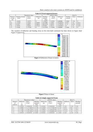
Figure 6 Stress in simply supported beam.
V. Conclusion
The numerical and theoretical results of deflection, bending moment and stresses etc have been
reported and correlated for a three disc rotor system for non-spinning condition. Both fixed and simply
supported boundary conditions have been simulated as an actual case may correspond to the one between these
two boundary conditions. Model of rotor system is created in ANSYS and analysis results are found considering
it as fixed beam as well as simply supported beam. Results of the same have been calculated theoretically. It is
found that ANSYS results of bending moment, stresses and deflection at the supports as well as interior points
almost matches with the theoretical results in case of simply supported beam . In -case of fixed-fixed beam, it is
seen that results of deflection from ANSYS closely matches with theoretical results both at supports and interior
point and the results of bending moment and stresses are close at the supports in the two cases. However, there
is some deviation in the results of bending moment and stresses at interior points in the two cases i.e. using
ANSYS and theory, though this deviation is also quite marginal.
References
[1]. A.S. Das , J. K. D. (2008). "Reduced model of a rotor-shaft system using modified SEREP." Mechanics Research Communications
35 (2008) 398–407.
[2]. Alsalaet, J. (2000). Rotor Dynamics. Basrah, College of Engineering University of Basrah.
[3]. Andrés, L. S. (2006). "Introduction to Pump Rotordynamics." Educational Notes RTO-EN-AVT-143.
[4]. BURGESS, A. (1988). TRANSIENT RESPONSE OF MECHANICAL STRUCTURES USING MODAL ANALYSIS
TECHNIQUES. Department of Mechanical Engineering,. London, University of London. degree of Doctor of Philosophy..
[5]. Crooymans, M. (1984). A survey of rotordynamics.
[6]. F. Vatta, A. V. (2007). "Internal damping in rotating shafts." Mechanism and Machine Theory.
[7]. J. GENIN, J. S. M. (1971). "The role of material damping in the stability of rotating systems." Journal of Sound and Vibration.
[8]. Lalanne, M. and G. Ferraris (1998). Rotordynamics Prediction in Engineering, John Wiley and Sons.
[9]. M. Chouksey, J. K. D., S.V. Modak (2012). "Modal analysis of rotor-shaft system under the influence of rotor-shaft material
damping and fluid film forces." Mechanism and Machine Theory.
[10]. M. Chouksey , J. K. D., S.V. Modak (2013). "Model updating of rotors supported on ball bearings
[11]. and its application in response prediction and balancing." Measurement.
[12]. MINGORI, D. L. (1973). "Stability of whirling shafts with internal and external damping." Non-Linear Mechanics.
[13]. MUSZYNSKA, A. (1995). "forward and backward precession of a vertical anisotropically supported rotor." Journal of Sound and
Vibration.
[14]. N. Wagner, R. H. (2013). "Dynamics of rotors in complex structures." NAFEMS World Congress:.
[15]. Nassis, A. (2010). Analyses of a Rotor Dynamic Testrigs. Mechanical Engineering. Sweden, Luleå University of Technology.
Master of science
[16]. Nelson, F. C. (2007). "Rotor Dynamics without Equations." International Journal of COMADEM,.
[17]. Ritesh Fegadea, V. P. (2013). "Unbalanced Response and Design Optimization of Rotor by ANSYS and Design Of Experiments."
International Journal of Scientific & Engineering Research, Volume 4(Issue 7).
[18]. Samuelsson, J. (2009). Rotor dynamic analysis of 3D-modeled gas turbine rotor in ANSYS. Department of Management and
Engineering, Linköping University.
[19]. Stefano Cutrona, S. D. L., Antonina Pirrotta Timoshenko vs Euler-Bernoulli beam: fractional visco-elastic behavior, Università
degli Studi di Palermo, Italy.