SlideShare a Scribd company logo
1 of 26
Download to read offline
1
Department Of Mechanical Engineering
COLLEGE OF ENGINEERING, PUNE-411005
A Seminar Report on
“Fuzzy Logic control for navigation of Bionic Robot”
Submitted in partial fulfilment of the requirements
of the degree of
Ravindra Shinde 111910141
Under the Guidance of
Prof. Dr. S. S. Ohol
Dept. of Mechanical Engineering
College of Engineering, Pune
(November 2022)
2
CERTIFICATE
This is to certify that the report entitled “Fuzzy Logic control for navigation of
Bionic Robot” submitted by Shinde Ravindra Rajendra (111910141) in the
partial fulfillment of the requirement for the award of degree of Bachelor of
Technology (Mechanical Engineering) of College of Engineering Pune, affiliated
to the Savitribai Phule Pune University, is a record of their own work.
Dr. S.S. Ohol Dr. M.R.Nandgaonkar
Associate Professor & Project Guide, Head of Department,
Mechanical Engineering Dept. Mechanical Engineering Dept.
College of Engineering Pune College of Engineering Pune
Date:
Place:
3
APPROVAL SHEET
This report entitled
“Fuzzy Logic control for navigation of Bionic Robot”
By
Shinde Ravindra Rajendra
(111910141)
is approved for the degree of
Bachelor of Technology with specialization in Mechanical Engineering
of
(Department of Mechanical Engineering)
College of Engineering Pune
(An autonomous institute of Govt. of Maharashtra)
Examiners Name Signature
1. External Examiner
2. Internal Examiner Prof. S.S. Ohol
Date:
Place:
4
DECLARATION
I declare that this written submission represents my ideas in my own words and
where others' ideas or words have been included, I have adequately cited and
referenced the original sources. I also declare that I have adhered to all principles
of academic honesty and integrity and have not misrepresented or fabricated or
falsified any idea/data/fact/source in my submission. I understand that any
violation of the above will be cause for disciplinary action by the Institute and
can also evoke penal action from the sources which have thus not been properly
cited or from whom proper permission has not been taken when needed.
_________________________________
(Signature)
__________________________________
(Name of the student)
_________________________________
(MIS No.)
Date:
Place:
5
ABSTRACT
This report gives idea about the Fuzzy logic and its implementation in the domain of
robot navigation. Also, it presents a fuzzy logic controller by which a robot can imitate
biological behaviours such as avoiding obstacles or following walls. Firstly, the concept of
fuzzy logic is discussing in detail. The proposed structure is implemented by integrating
multiple ultrasonic sensors into a robot to collect data from a real-world environment. The
validity of the proposed controller was demonstrated by simulating three real world scenarios
to test the bionic behaviour of a custom-built robot. The results revealed satisfactorily
intelligent performance of the proposed fuzzy logic controller. The controller enabled the robot
to demonstrate intelligent behaviours in complex environments. Furthermore, the robot’s
bionic functions satisfied its design objectives.
6
TABLE OF CONTENT
Page No.
Certificate 2
Approval sheet 3
Declaration 4
Abstract 5
Chapter 1: Introduction 9
Chapter 2: Fuzzy Logic 10
2.1 Basic Overview 11
2.2 Architecture of the system 12
2.3 Fuzzy inference System (FIS) 13
Chapter 3: Behaviour of Bionic robot 15
3.1 System description 15
3.2 Design for Obstacle Avoidance 18
3.3 Design for Wall Following 20
3.4 Validation of logic in different scenario’s 23
Chapter 4: Conclusion 25
References 26
7
LIST OF FIGURES Page No.
Fig. 1: Boolean logic Vs Fuzzy logic 10
Fig. 2: Fuzzy Logic architecture 10
Fig. 3: Triangular membership function 11
Fig. 4: Trapezoidal membership function 11
Fig. 5: Gaussian membership function 12
Fig. 6: Some other membership functions 12
Fig. 7: Appearance of the MIAT six-legged robot 15
Fig. 8(a): Ultrasonic sensor 16
Fig. 8(b): Position of sensor on robot 16
Fig. 8(c): Six-foot robot control architecture 16
Fig.9: Foot movement angle relative relation diagram 17
Fig.10: Obstacle avoidance process 18
Fig. 11: MF of obstacle avoidance fuzzy controller. 19
Fig. 12: Illustration of wall following 21
Fig. 13: Wall following procedure 21
Fig. 14: MF of wall following fuzzy controller 22
Fig. 15: Fuzzy control surface for wall following 23
Fig. 16: Moving path of Scenario 1 23
Fig. 17: Moving path of Scenario 2 24
Fig. 18: Moving path of Scenario 3 25
8
LIST OF TABLES Page No.
Table 1: Comparison between Mamdani and Sugeno FIS 14
Table 2: Foot movement data 18
Table 3: Fuzzy rules for obstacle avoidance 20
Table 3: Linguistic variables for Inputs and output 22
Table 4: Rules for wall following 22
LIST OF ABBREVIATION
MCU : Multipoint Control Unit
PC : Personal Computer
UART : Universal Asynchronous Receiver-Transmitter
RF : Radio Frequency
9
Chapter 1
INTRODUCTION
Robot research is popular scientific research and is undoubtedly to enhance the quality of
human life, but in the environment, the wheel structure is not suitable for use in the rugged
terrain environment; in it is very easy to study insects, whether they are moving on flat roads
or walking on irregular roads.
With the increasingly widespread application of robots in today’s fast-changing and diverse
environment, it is essential for robots to possess autonomous movement capacity and intelligent
decision-making processes, as well as behavioural control through sensory awareness of the
surrounding environment to complete tasks in complex situations. In this regard, navigation
and obstacle avoidance are the two crucial concerns that require attention.
Fuzzy logic has been deemed appropriate for applications in automatic navigation of robots.
This is mainly because of its capacity to process large quantities of incomplete and inaccurate
input signals. Such signal processing can enable automatic navigation for robots in uncertain
environments. Abundant research has been reported on the application of fuzzy theory in
automatic navigation for robots. A typical application requires the robot to carry various
sensors for sensing environmental information. The outputs of the sensors serve as inputs to
the fuzzy controller. Expert experience is adopted to prebuild a fuzzy rule database, which is
required for the robot’s subsequent behaviours. Fuzzification, fuzzy inference, and
defuzzification generate decisions that control the robot’s behaviours enabling the robot to
navigate automatically.
A fuzzy logic controller can accept input from a diverse range of sensors. Ultrasonic sensors
can detect the distance between a robot and obstacles. Global positioning systems can detect
the robot’s current position. With fuzzy inference, the final output enables a robot to
differentiate between various environments and to perform the behaviours desired by the
designer. For example, differences in wheel speeds can enable a wheeled robot to turn at an
angle and roll in a new direction to avoid an obstacle. Regarding multilegged robots, the final
input may be the rotational angle or forward velocity at present, the development of the living
tools and the adaptability of the environment are far less than the evolution of the ability of
organisms, regardless of how long these organisms are experiencing long-term evolution, and
whether there is a high degree of adaptability to the habitat of living space, whether it is in
sensory organs, exercise patterns, learning mechanisms, organ structures, monomers, or all life
structures, which is more efficient, so the use of physical characteristics will be an important
future development indicator. This study focuses on the behaviour of the recurrence of
biological patterns for the software direction, the use of its evolution and behaviour patterns,
and the software processing efficiency.
10
Chapter 2
Fuzzy Logic
2.1 Basic overview
The term fuzzy refers to things that are not clear or are vague. In the real world many times
we encounter a situation when we can’t determine whether the state is true or false, their
fuzzy logic provides very valuable flexibility for reasoning. In this way, we can consider the
inaccuracies and uncertainties of any situation.
In the Boolean system truth value, 1 represents the absolute truth value and 0 represents the
absolute false value. But in the fuzzy system, there is no logic for the absolute truth and absolute
false value. But in fuzzy logic, there is an intermediate value too present which is partially true
and partially false.
Fig. 1: Boolean logic Vs Fuzzy logic
2.2 Architecture of the system
Fig. 2: Fuzzy Logic architecture
11
Its Architecture contains four parts:
1. RULE BASE: It contains the set of rules and the IF-THEN conditions provided by
the expertise or past experiences to govern the decision-making system, based on
linguistic information. Recent developments in fuzzy theory offer several effective
methods for the design and tuning of fuzzy controllers. Most of these developments
reduce the number of fuzzy rules.
2. FUZZIFICATION: It is used to convert inputs i.e., crisp numbers into fuzzy sets.
Crisp inputs are basically the exact inputs measured by sensors and passed into the
control system for processing, such as temperature, pressure, rpm’s, etc. To convert
this crisp input variable into the fuzzy variable membership functions are used.
a. Membership functions: A graph that defines how each point in the input
space is mapped to membership value between 0 and 1. Input space is often
referred to as the universe of discourse or universal set (u), which contains all
the possible elements of concern in each application.
There are many types of membership functions used for fuzzification stage.
Some of them are shown in below figures.
Fig. 3: Trapezoidal membership function
12
Fig. 4: Triangular membership function
Fig. 5: Gaussian membership function
Fig. 6: Some other membership functions
3. INFERENCE ENGINE: It determines the matching degree of the current fuzzy input
with respect to each rule and decides which rules are to be fired according to the input
field. Next, the fired rules are combined to form the control actions.
4. DEFUZZIFICATION: It is used to convert the fuzzy sets obtained by the inference
engine into a crisp value. As like fuzzification stage, defuzzification stage also
requires membership function of crisp output variable. They are same as that of
shown in above mentioned figure. Again, selection of membership function is totally
13
based on expertise and experience person having. Sometimes surveys are also
conducted to get data for plotting of membership function. There are several
defuzzification methods available and the best-suited one is used with a specific
expert system to reduce the error.
a. Different defuzzification techniques:
i. Centre of gravity (COG)
ii. Mean of max (MOM)
iii. Centre of area (COA)
2.3 Fuzzy inference system (FIS):
It is the system to interpret the values of the input vector and, based on some sets of fuzzy
rules, it assigns corresponding values to the output vector. This system contains simple IF
THEN or IF-ELSE rules that take fuzzy set as input, process it based on logic stored and give
output as fuzzy set only. This is a method to map an input to an output using fuzzy logic.
Based on this mapping process, the system takes decisions and distinguishes patterns.
There are two main types of fuzzy inference systems: Mamdani FIS and Sugeno FIS.
2.3.1 Mamdani FIS –
The Mamdani fuzzy inference system was proposed by Ebhasim Mamdani. Firstly, it was
designed to control a steam engine and boiler combination by a set of linguistic control rules
obtained from the experienced human operators. In Mamdani inference system, the output of
each rule to be a fuzzy logic set. Here actual IF-Else rules need to be developed for program
execution.
2.3.2 Sugeno FIS –
This fuzzy inference system was proposed by Takagi, Sugeno, and Kang to develop a
systematic approach for generating fuzzy rules from a given input-output dataset. A typical
fuzzy rule in a first order Sugeno fuzzy model has the form: Here mathematical equation is
formed based on linguistic rules.
IF x is A and y is B THEN z = f(x, y)
were
A and B are fuzzy sets in the antecedent
z = f (x, y) is a crisp function in the consequent.
Higher-order Sugeno fuzzy models are also possible, but while designing, those introduce
significant complexity.
Though there is one similarity worth be mentioned between Mamdani and Sugeno Fuzzy
Inference System, the antecedent parts of these both of the FIS rules are same.
14
Table 1: Comparison between Mamdani and Sugeno FIS
Mamdani FIS Sugeno FIS
Output membership function is present No output membership function is present
The output of surface is discontinuous The output of surface is continuous
Distribution of output Non distribution of output, only
Mathematical combination of the output
and the rules strength
Through defuzzification of rules consequent of
crisp result is obtained
No defuzzification here. Using weighted
average of the rules of consequent crisp
result is obtained
Expressive power and interpretable rule
consequent
Here is loss of interpretability
Mamdani FIS possess less flexibility in the
system design
Sugeno FIS possess more flexibility in the
system design
It has more accuracy in security evaluation
block cipher algorithm
It has less accuracy in security evaluation
block cipher algorithm
It is using in MISO (Multiple Input and Single
Output) and MIMO (Multiple Input and
Multiple Output) systems
It is using only in MISO (Multiple Input
and Single Output) systems
Mamdani inference system is well suited to
human input
Sugeno inference system is well suited to
mathematically analysis
Application: Medical Diagnosis System Application: To keep track of the change in
aircraft performance with altitude
15
Chapter 3
Behaviour of Bionic Robot
The term “bionic robots” refers to robots that mimic the body structures, functions, problem
solving behaviour, and motions of living creatures, with simple mechanical structures or
electronic devices. Multilegged bionic robots belong to this category; their motion patterns
and tread movements resemble those of insects and spiders. Such a robot uses each leg, with
its embedded multiple rotational joints, to mimic the behavioural patterns of insects. Among
such robots, the six-legged type (Hexapods)is the most common type of bionic robot.
Fig. 7: Appearance of the MIAT six-legged robot
3.1 System description
Multiple sets of ultrasonic distance measurements were used as input to develop an intelligent
navigation system. With this distance information, the fuzzy logic controller enabled the
robot to safely complete tasks in an unknown environment. An individual ultrasonic sensor is
shown in Figure 8(a). The positions of the distance sensing ultrasonic sensors are shown in
Figure 8(b): right (S1), front (S2), left (S3), right front (S4), and left front (S5).
16
Fig. 8(a): Ultrasonic sensor Fig. 8(b): Position of sensor on robot
Six-foot robot body uses 18 servo motors, six MCU sub controllers, UART message
transmission, and the main controller of the news, and the design of wireless monitoring
equipment, the use of RF module for two-way data transmission, and timely feedback related
information and PC are used to analyse the action. The master/slave controller system can
communicate with each other through the Bluetooth system and the monitoring system, and
the monitoring system can manually operate the six-legged robot manually.
Fig. 8(c): Six-foot robot control architecture
Figure 9 shows foot movement angle relative relationship; M2 will be disturbed by the M2-
M3 mechanism and the M2 motor mechanism; it must be specified within ±40∘, to face the
adjacent body operation collision damage. M3 mechanism set contact with the ground for the
vertical ground 90∘, so theM2 and M3 must be the opposite of the servo motor angle; related
mechanical joints are as follows:
M2 − M3 = 57 mm.
M2-Machine bottom = 42.7 mm.
M3-the ground = 108 mm.
17
L1 = 26.62 mm.
H3 = 42.7 mm.
H2 = sin 𝜃∗ (M2 − M3).
H4 = H2 + L3 − H3 = sin 𝜃∗ 57mm + 108mm −
42.7 mm.
Using the above formula, the design of Figure 3 shows the movement angle and displacement
of the map were from 0∘, 10∘, 20∘, 30∘, 40∘, −10∘, −20∘, −30∘, and −40∘, for foot control
design. And then the corresponding H2 and H4 movement angle and displacement volume
are as shown in Table 1. Each foot institution is limited to positive and negative60 degrees as
a range of services, such as the six-foot body map shown in Figure 4, to avoid the impact of
mutual action agencies and to prevent damage to the organization.
Fig. 9: Foot movement angle relative relation diagram
18
Table 2: Foot movement data.
3.2 Design for Obstacle Avoidance:
Fig.10: Obstacle avoidance process.
19
Above figure shows obstacle avoidance is a priority for a moving robot that must avoid
obstacles and prevent collisions. The distance information collected from sensors 1, 2, and 3
is used for the ultrasonic sensing system. The complete obstacle avoidance procedure, in
which the robot receives the ultrasonically sensed distances, from front, right, and left
sensors, defined as 𝑑𝑓, 𝑑𝑟, 𝑑𝑙, respectively. These three distance variables are fed as input into
the obstacle avoidance fuzzy controller. The motor control board calculates the velocity of
the robot (𝑉𝑒) and directional angles to be modified (𝜃𝑒). Each input to the fuzzy controller is
assigned the same membership function (MF), as illustrated in Figure 6(a). All the MFs are
triangular.
Fig. 11: MF of obstacle avoidance fuzzy controller. (a) MFs of inputs 𝑑𝑓, 𝑑𝑟, and 𝑑𝑙 . (b)
MF of output 𝜃𝑒; (c) MF of output 𝑉𝑒.
The sensor distances are measured in cm and robot speed is measured in cm/s. For the real-
world robot, the widely known max–min operation was used in the fuzzy inference, and the
centre of-gravity method was adopted in defuzzification. Regarding the fuzzy rule database,
the researchers’ experience and knowledge of partially successful attempts were utilized to
build relevant rules, as shown in Table 4.
20
Table 3: Fuzzy rules for obstacle avoidance
3.3 Design for Wall Following.
The robot can follow walls, thus enabling it to walk along the boundaries of the testing
environment. The operational definition is “motion in a direction parallel to the nearest wall
at a consistent distance from that wall.” The procedure for wall following is illustrated in
Figure 11.
21
Fig. 12: Illustration of wall following
In Case A, the robot first detects a shorter distance from the left wall and moves along it.
Because the robot’s motion is parallel to the wall, the robot-wall distance differences in the
two cycles should be zero, thus requiring no angular modification. In Case B, the robot
begins to deviate from the left wall; thus, the robot-wall distance difference between the two
cycles should increase. Using the distance difference and the current velocity as inputs to the
fuzzy logic controller, a turning angle𝜃𝑒 toward the wall can be obtained, enabling the robot
to turn toward the wall and return to correct the wall following behaviour.
The difference between the wall distances in the two cycles (𝑑𝑒) is then taken as one of the
inputs to the fuzzy logic controller. The other input is the velocity of the robot(𝑉𝑐). The fuzzy
rules employed for this control is enlist in Table 8.
Fig. 13: Wall following procedure
22
Table 4: Linguistic variables for Inputs and output
The membership functions consider for input and output are triangular only. The model is
built in MATLAB and the results are obtained is showed in below control surface.
Fig. 14: MF of wall following fuzzy controller (a) MFs of input 𝑑𝑒. (b) MF of input 𝑉𝑐.
(c) MF of output 𝜃𝑒.
Table 5: Fuzzy rules for wall following
23
The control surface obtained in MATLAB is shown in below figure.
Fig. 15: Fuzzy control surface for wall following
3.4 Validation of proposed logic:
After the robot’s bionic behaviour controlling chip was designed and implemented, the chip
was installed in a real robot for function verification and performance analysis. The hardware
comprised a field programmable gate array board, motor control board, and a six-legged
robot, as shown in Figure 1(b).
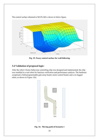
Fig. 16: Moving path of Scenario 1
24
Scenario 1: The path was 1m wide, and the width of the obstacle (a rectangular solid) was 20
cm. As shown in Figure 15, the robot first moved upward following instructions from the
developed fuzzy database. While moving, the robot detected objects on both its sides at Point
A but continued to move forward because the distance ahead was still considerable. The
robot detected an object close ahead and a wall blocking its right side when it reached Point
B. Immediately, the fuzzy logic controller responded with a left turn. At Point C, obstacles
were present at the front and on the left side. The obstacle on the right side was farther away;
therefore, the fuzzy logic controller responded with a right turn. With no further obstacles
lying ahead, the robot continued moving forward.
Fig. 17: Moving path of Scenario 2
Scenario 2: Dead End with Three Surrounding Walls. The purpose of this experiment was to
examine whether the robot could make its way out of a dead end. The dead end was 50 cm
wide, as shown in Figure 16. The robot moved forward, following instructions from the
developed fuzzy database. As it moved, it detected objects on both sides at Point A.
However, it continued moving forward because there was a considerable expanse of empty
space before it. At Point B, the robot then detected an object that obstructed its forward path
and a wall blocking its right side. Immediately, the fuzzy logic controller responded with a
left turn. At Point C, the obstacles appeared at the front and on the left side. The obstacle to
the left side was more distant; thus, the fuzzy controller ordered a left turn. At Point D, the
robot turned left because no obstacles were found on the left. After the robot had turned, it
found no further obstacles lying ahead and continued to move forward.
25
Fig. 18: Moving path of Scenario 3
Scenario 3: Wall Following and Obstacle Avoidance. This experiment tested whether the
proposed navigation system correctly integrated wall following, obstacle avoidance, and
target tracing. As shown in Figure 17, the wall was 60 cm long, and the obstacle (a
rectangular solid) was 20 cm wide. At Point A, the robot calculated that its conditions called
for a wall following behaviour. At Point B, the robot deviated gradually from the wall, and
the fuzzy controller modified the robot’s direction away from the wall. At Point C, the robot
detected obstacles at its front and on its left side. In the proposed integrated system, obstacle
avoidance has higher priority than wall following does; the fuzzy controller ordered a right
turn, and the robot turned right and performed obstacle avoidance.
In the current study, a real robot was tested; the accuracy levels of its intelligent behavioural
functions were verified. Thus, three scenarios were designed to examine the robot’s bionic
behaviours. The results reveal that the proposed fuzzy logic controller enabled the robot to
perform in complex environments and to demonstrate intelligent behaviours. The robot was
designed for bionic functions; its performance demonstrated those bionic functions.
4. Conclusions
In this report we use fuzzy logic to realise the reactive behaviour for robot navigation. The
method can effectively coordinate composites and competition among multiple reactive
behaviours by beating them and this coordination ability is nearly independent of dynamic
environment due to its robustness. The navigation algorithm has better reliability and real
time response sense perception and decision unit in integrated in one model and directly
oriented to a dynamic environment. The simulation result shows that propose method of the
navigation by multi sensor integration start automatically performing avoiding obstacles,
following edge of wall, escaping u shaped object in complex and uncertain environment
26
REFERENCES:
1. C. Chen, C. Wang,Y. Wang, and P.Wang, ‘Fuzzy Logic Controller Design for
Intelligent Robots’, in Proceedings of the IEEE International Conference on
Control Applications, , IEEE, 2017https://doi.org/10.1155/2017/8984713.
2. https://www.geeksforgeeks.org/fuzzy-logic-introduction/
3. N.Singh,K.Thongan, “Mobile robot navigation using Fuzzy Logic in static
environment”, in 6th international conference in Smart compting and
communication, ICSCC 2017.
4. A.Rath, D.parhi, H.Dase,M.Muni, P.Kumar, “Analysis and use of fuzzy intelligent
technique for navigation of humanoid robot in obstacle prone zone”, Defence
Technology Article, ELSEVIER.
5. U.Farooq, M. Asad, M.Amar, A. Hanif, S. Saleh, “Fuzzy Logic Based Real Time
Obstacle Avoidance Controller for a Simplified Model of Hexapod Walking Robot”,
International Journal of Computer and Electrical Engineering, Vol. 6, No. 2, April
2014.
6. M. Ibrahima, D. Hanafib, R. Ghonia, “Autonomous Navigation for a Dynamical
Hexapod Robot using Fuzzy Logic Controller” , International Conference on
Modeling Optimisation and Computing 2012.

More Related Content

Similar to Fuzzy logic control for robot navigation

Learning of robot navigation tasks by
Learning of robot navigation tasks byLearning of robot navigation tasks by
Learning of robot navigation tasks bycsandit
 
LEARNING OF ROBOT NAVIGATION TASKS BY PROBABILISTIC NEURAL NETWORK
LEARNING OF ROBOT NAVIGATION TASKS BY PROBABILISTIC NEURAL NETWORKLEARNING OF ROBOT NAVIGATION TASKS BY PROBABILISTIC NEURAL NETWORK
LEARNING OF ROBOT NAVIGATION TASKS BY PROBABILISTIC NEURAL NETWORKcsandit
 
Introduction to the Special issue on ‘‘Future trends in robotics and autonomo...
Introduction to the Special issue on ‘‘Future trends in robotics and autonomo...Introduction to the Special issue on ‘‘Future trends in robotics and autonomo...
Introduction to the Special issue on ‘‘Future trends in robotics and autonomo...Anand Bhojan
 
EFFECTIVE REDIRECTING OF THE MOBILE ROBOT IN A MESSED ENVIRONMENT BASED ON TH...
EFFECTIVE REDIRECTING OF THE MOBILE ROBOT IN A MESSED ENVIRONMENT BASED ON TH...EFFECTIVE REDIRECTING OF THE MOBILE ROBOT IN A MESSED ENVIRONMENT BASED ON TH...
EFFECTIVE REDIRECTING OF THE MOBILE ROBOT IN A MESSED ENVIRONMENT BASED ON TH...ijfls
 
EFFECTIVE REDIRECTING OF THE MOBILE ROBOT IN A MESSED ENVIRONMENT BASED ON TH...
EFFECTIVE REDIRECTING OF THE MOBILE ROBOT IN A MESSED ENVIRONMENT BASED ON TH...EFFECTIVE REDIRECTING OF THE MOBILE ROBOT IN A MESSED ENVIRONMENT BASED ON TH...
EFFECTIVE REDIRECTING OF THE MOBILE ROBOT IN A MESSED ENVIRONMENT BASED ON TH...Wireilla
 
Smart element aware gate controller for intelligent wheeled robot navigation
Smart element aware gate controller for intelligent wheeled robot navigationSmart element aware gate controller for intelligent wheeled robot navigation
Smart element aware gate controller for intelligent wheeled robot navigationIJECEIAES
 
Mobile robot controller using novel hybrid system
Mobile robot controller using novel hybrid system  Mobile robot controller using novel hybrid system
Mobile robot controller using novel hybrid system IJECEIAES
 
Intelligent Robotics Navigation System: Problems, Methods, and Algorithm
Intelligent Robotics Navigation System: Problems,  Methods, and Algorithm Intelligent Robotics Navigation System: Problems,  Methods, and Algorithm
Intelligent Robotics Navigation System: Problems, Methods, and Algorithm IJECEIAES
 
Multisensor data fusion based autonomous mobile
Multisensor data fusion based autonomous mobileMultisensor data fusion based autonomous mobile
Multisensor data fusion based autonomous mobileeSAT Publishing House
 
Multirotor control ua vs based on fuzzy logic
Multirotor control ua vs based on fuzzy logicMultirotor control ua vs based on fuzzy logic
Multirotor control ua vs based on fuzzy logicAntonio Chica
 
Evolutionary Design of Backstepping Artificial Sliding Mode Based Position Al...
Evolutionary Design of Backstepping Artificial Sliding Mode Based Position Al...Evolutionary Design of Backstepping Artificial Sliding Mode Based Position Al...
Evolutionary Design of Backstepping Artificial Sliding Mode Based Position Al...CSCJournals
 
A Multi-robot System Coordination Design and Analysis on Wall Follower Robot ...
A Multi-robot System Coordination Design and Analysis on Wall Follower Robot ...A Multi-robot System Coordination Design and Analysis on Wall Follower Robot ...
A Multi-robot System Coordination Design and Analysis on Wall Follower Robot ...IJECEIAES
 
Scheme for motion estimation based on adaptive fuzzy neural network
Scheme for motion estimation based on adaptive fuzzy neural networkScheme for motion estimation based on adaptive fuzzy neural network
Scheme for motion estimation based on adaptive fuzzy neural networkTELKOMNIKA JOURNAL
 
Foot Mounted Pedestrian Navigation Systems
Foot Mounted Pedestrian Navigation SystemsFoot Mounted Pedestrian Navigation Systems
Foot Mounted Pedestrian Navigation Systemsoblu.io
 
Swarm Intelligence for Logistics Controlling
Swarm Intelligence for Logistics ControllingSwarm Intelligence for Logistics Controlling
Swarm Intelligence for Logistics ControllingIRJET Journal
 
Inverse kinematic analysis of 4 DOF pick and place arm robot manipulator usin...
Inverse kinematic analysis of 4 DOF pick and place arm robot manipulator usin...Inverse kinematic analysis of 4 DOF pick and place arm robot manipulator usin...
Inverse kinematic analysis of 4 DOF pick and place arm robot manipulator usin...IJECEIAES
 

Similar to Fuzzy logic control for robot navigation (20)

Learning of robot navigation tasks by
Learning of robot navigation tasks byLearning of robot navigation tasks by
Learning of robot navigation tasks by
 
LEARNING OF ROBOT NAVIGATION TASKS BY PROBABILISTIC NEURAL NETWORK
LEARNING OF ROBOT NAVIGATION TASKS BY PROBABILISTIC NEURAL NETWORKLEARNING OF ROBOT NAVIGATION TASKS BY PROBABILISTIC NEURAL NETWORK
LEARNING OF ROBOT NAVIGATION TASKS BY PROBABILISTIC NEURAL NETWORK
 
K010218188
K010218188K010218188
K010218188
 
Introduction to the Special issue on ‘‘Future trends in robotics and autonomo...
Introduction to the Special issue on ‘‘Future trends in robotics and autonomo...Introduction to the Special issue on ‘‘Future trends in robotics and autonomo...
Introduction to the Special issue on ‘‘Future trends in robotics and autonomo...
 
Seminar ppt
Seminar pptSeminar ppt
Seminar ppt
 
EFFECTIVE REDIRECTING OF THE MOBILE ROBOT IN A MESSED ENVIRONMENT BASED ON TH...
EFFECTIVE REDIRECTING OF THE MOBILE ROBOT IN A MESSED ENVIRONMENT BASED ON TH...EFFECTIVE REDIRECTING OF THE MOBILE ROBOT IN A MESSED ENVIRONMENT BASED ON TH...
EFFECTIVE REDIRECTING OF THE MOBILE ROBOT IN A MESSED ENVIRONMENT BASED ON TH...
 
EFFECTIVE REDIRECTING OF THE MOBILE ROBOT IN A MESSED ENVIRONMENT BASED ON TH...
EFFECTIVE REDIRECTING OF THE MOBILE ROBOT IN A MESSED ENVIRONMENT BASED ON TH...EFFECTIVE REDIRECTING OF THE MOBILE ROBOT IN A MESSED ENVIRONMENT BASED ON TH...
EFFECTIVE REDIRECTING OF THE MOBILE ROBOT IN A MESSED ENVIRONMENT BASED ON TH...
 
Smart element aware gate controller for intelligent wheeled robot navigation
Smart element aware gate controller for intelligent wheeled robot navigationSmart element aware gate controller for intelligent wheeled robot navigation
Smart element aware gate controller for intelligent wheeled robot navigation
 
Mobile robot controller using novel hybrid system
Mobile robot controller using novel hybrid system  Mobile robot controller using novel hybrid system
Mobile robot controller using novel hybrid system
 
Intelligent Robotics Navigation System: Problems, Methods, and Algorithm
Intelligent Robotics Navigation System: Problems,  Methods, and Algorithm Intelligent Robotics Navigation System: Problems,  Methods, and Algorithm
Intelligent Robotics Navigation System: Problems, Methods, and Algorithm
 
Multisensor data fusion based autonomous mobile
Multisensor data fusion based autonomous mobileMultisensor data fusion based autonomous mobile
Multisensor data fusion based autonomous mobile
 
Multirotor control ua vs based on fuzzy logic
Multirotor control ua vs based on fuzzy logicMultirotor control ua vs based on fuzzy logic
Multirotor control ua vs based on fuzzy logic
 
Medical robots history
Medical robots historyMedical robots history
Medical robots history
 
Evolutionary Design of Backstepping Artificial Sliding Mode Based Position Al...
Evolutionary Design of Backstepping Artificial Sliding Mode Based Position Al...Evolutionary Design of Backstepping Artificial Sliding Mode Based Position Al...
Evolutionary Design of Backstepping Artificial Sliding Mode Based Position Al...
 
A Multi-robot System Coordination Design and Analysis on Wall Follower Robot ...
A Multi-robot System Coordination Design and Analysis on Wall Follower Robot ...A Multi-robot System Coordination Design and Analysis on Wall Follower Robot ...
A Multi-robot System Coordination Design and Analysis on Wall Follower Robot ...
 
Scheme for motion estimation based on adaptive fuzzy neural network
Scheme for motion estimation based on adaptive fuzzy neural networkScheme for motion estimation based on adaptive fuzzy neural network
Scheme for motion estimation based on adaptive fuzzy neural network
 
A010430107
A010430107A010430107
A010430107
 
Foot Mounted Pedestrian Navigation Systems
Foot Mounted Pedestrian Navigation SystemsFoot Mounted Pedestrian Navigation Systems
Foot Mounted Pedestrian Navigation Systems
 
Swarm Intelligence for Logistics Controlling
Swarm Intelligence for Logistics ControllingSwarm Intelligence for Logistics Controlling
Swarm Intelligence for Logistics Controlling
 
Inverse kinematic analysis of 4 DOF pick and place arm robot manipulator usin...
Inverse kinematic analysis of 4 DOF pick and place arm robot manipulator usin...Inverse kinematic analysis of 4 DOF pick and place arm robot manipulator usin...
Inverse kinematic analysis of 4 DOF pick and place arm robot manipulator usin...
 

Recently uploaded

Platformless Horizons for Digital Adaptability
Platformless Horizons for Digital AdaptabilityPlatformless Horizons for Digital Adaptability
Platformless Horizons for Digital AdaptabilityWSO2
 
presentation ICT roal in 21st century education
presentation ICT roal in 21st century educationpresentation ICT roal in 21st century education
presentation ICT roal in 21st century educationjfdjdjcjdnsjd
 
Cloud Frontiers: A Deep Dive into Serverless Spatial Data and FME
Cloud Frontiers:  A Deep Dive into Serverless Spatial Data and FMECloud Frontiers:  A Deep Dive into Serverless Spatial Data and FME
Cloud Frontiers: A Deep Dive into Serverless Spatial Data and FMESafe Software
 
MINDCTI Revenue Release Quarter One 2024
MINDCTI Revenue Release Quarter One 2024MINDCTI Revenue Release Quarter One 2024
MINDCTI Revenue Release Quarter One 2024MIND CTI
 
Navigating the Deluge_ Dubai Floods and the Resilience of Dubai International...
Navigating the Deluge_ Dubai Floods and the Resilience of Dubai International...Navigating the Deluge_ Dubai Floods and the Resilience of Dubai International...
Navigating the Deluge_ Dubai Floods and the Resilience of Dubai International...Orbitshub
 
FWD Group - Insurer Innovation Award 2024
FWD Group - Insurer Innovation Award 2024FWD Group - Insurer Innovation Award 2024
FWD Group - Insurer Innovation Award 2024The Digital Insurer
 
DBX First Quarter 2024 Investor Presentation
DBX First Quarter 2024 Investor PresentationDBX First Quarter 2024 Investor Presentation
DBX First Quarter 2024 Investor PresentationDropbox
 
Connector Corner: Accelerate revenue generation using UiPath API-centric busi...
Connector Corner: Accelerate revenue generation using UiPath API-centric busi...Connector Corner: Accelerate revenue generation using UiPath API-centric busi...
Connector Corner: Accelerate revenue generation using UiPath API-centric busi...DianaGray10
 
Apidays New York 2024 - The Good, the Bad and the Governed by David O'Neill, ...
Apidays New York 2024 - The Good, the Bad and the Governed by David O'Neill, ...Apidays New York 2024 - The Good, the Bad and the Governed by David O'Neill, ...
Apidays New York 2024 - The Good, the Bad and the Governed by David O'Neill, ...apidays
 
Apidays New York 2024 - APIs in 2030: The Risk of Technological Sleepwalk by ...
Apidays New York 2024 - APIs in 2030: The Risk of Technological Sleepwalk by ...Apidays New York 2024 - APIs in 2030: The Risk of Technological Sleepwalk by ...
Apidays New York 2024 - APIs in 2030: The Risk of Technological Sleepwalk by ...apidays
 
"I see eyes in my soup": How Delivery Hero implemented the safety system for ...
"I see eyes in my soup": How Delivery Hero implemented the safety system for ..."I see eyes in my soup": How Delivery Hero implemented the safety system for ...
"I see eyes in my soup": How Delivery Hero implemented the safety system for ...Zilliz
 
[BuildWithAI] Introduction to Gemini.pdf
[BuildWithAI] Introduction to Gemini.pdf[BuildWithAI] Introduction to Gemini.pdf
[BuildWithAI] Introduction to Gemini.pdfSandro Moreira
 
Finding Java's Hidden Performance Traps @ DevoxxUK 2024
Finding Java's Hidden Performance Traps @ DevoxxUK 2024Finding Java's Hidden Performance Traps @ DevoxxUK 2024
Finding Java's Hidden Performance Traps @ DevoxxUK 2024Victor Rentea
 
ProductAnonymous-April2024-WinProductDiscovery-MelissaKlemke
ProductAnonymous-April2024-WinProductDiscovery-MelissaKlemkeProductAnonymous-April2024-WinProductDiscovery-MelissaKlemke
ProductAnonymous-April2024-WinProductDiscovery-MelissaKlemkeProduct Anonymous
 
Architecting Cloud Native Applications
Architecting Cloud Native ApplicationsArchitecting Cloud Native Applications
Architecting Cloud Native ApplicationsWSO2
 
ICT role in 21st century education and its challenges
ICT role in 21st century education and its challengesICT role in 21st century education and its challenges
ICT role in 21st century education and its challengesrafiqahmad00786416
 
Mcleodganj Call Girls 🥰 8617370543 Service Offer VIP Hot Model
Mcleodganj Call Girls 🥰 8617370543 Service Offer VIP Hot ModelMcleodganj Call Girls 🥰 8617370543 Service Offer VIP Hot Model
Mcleodganj Call Girls 🥰 8617370543 Service Offer VIP Hot ModelDeepika Singh
 
Six Myths about Ontologies: The Basics of Formal Ontology
Six Myths about Ontologies: The Basics of Formal OntologySix Myths about Ontologies: The Basics of Formal Ontology
Six Myths about Ontologies: The Basics of Formal Ontologyjohnbeverley2021
 
TrustArc Webinar - Unlock the Power of AI-Driven Data Discovery
TrustArc Webinar - Unlock the Power of AI-Driven Data DiscoveryTrustArc Webinar - Unlock the Power of AI-Driven Data Discovery
TrustArc Webinar - Unlock the Power of AI-Driven Data DiscoveryTrustArc
 

Recently uploaded (20)

Platformless Horizons for Digital Adaptability
Platformless Horizons for Digital AdaptabilityPlatformless Horizons for Digital Adaptability
Platformless Horizons for Digital Adaptability
 
presentation ICT roal in 21st century education
presentation ICT roal in 21st century educationpresentation ICT roal in 21st century education
presentation ICT roal in 21st century education
 
Cloud Frontiers: A Deep Dive into Serverless Spatial Data and FME
Cloud Frontiers:  A Deep Dive into Serverless Spatial Data and FMECloud Frontiers:  A Deep Dive into Serverless Spatial Data and FME
Cloud Frontiers: A Deep Dive into Serverless Spatial Data and FME
 
MINDCTI Revenue Release Quarter One 2024
MINDCTI Revenue Release Quarter One 2024MINDCTI Revenue Release Quarter One 2024
MINDCTI Revenue Release Quarter One 2024
 
Navigating the Deluge_ Dubai Floods and the Resilience of Dubai International...
Navigating the Deluge_ Dubai Floods and the Resilience of Dubai International...Navigating the Deluge_ Dubai Floods and the Resilience of Dubai International...
Navigating the Deluge_ Dubai Floods and the Resilience of Dubai International...
 
FWD Group - Insurer Innovation Award 2024
FWD Group - Insurer Innovation Award 2024FWD Group - Insurer Innovation Award 2024
FWD Group - Insurer Innovation Award 2024
 
DBX First Quarter 2024 Investor Presentation
DBX First Quarter 2024 Investor PresentationDBX First Quarter 2024 Investor Presentation
DBX First Quarter 2024 Investor Presentation
 
Understanding the FAA Part 107 License ..
Understanding the FAA Part 107 License ..Understanding the FAA Part 107 License ..
Understanding the FAA Part 107 License ..
 
Connector Corner: Accelerate revenue generation using UiPath API-centric busi...
Connector Corner: Accelerate revenue generation using UiPath API-centric busi...Connector Corner: Accelerate revenue generation using UiPath API-centric busi...
Connector Corner: Accelerate revenue generation using UiPath API-centric busi...
 
Apidays New York 2024 - The Good, the Bad and the Governed by David O'Neill, ...
Apidays New York 2024 - The Good, the Bad and the Governed by David O'Neill, ...Apidays New York 2024 - The Good, the Bad and the Governed by David O'Neill, ...
Apidays New York 2024 - The Good, the Bad and the Governed by David O'Neill, ...
 
Apidays New York 2024 - APIs in 2030: The Risk of Technological Sleepwalk by ...
Apidays New York 2024 - APIs in 2030: The Risk of Technological Sleepwalk by ...Apidays New York 2024 - APIs in 2030: The Risk of Technological Sleepwalk by ...
Apidays New York 2024 - APIs in 2030: The Risk of Technological Sleepwalk by ...
 
"I see eyes in my soup": How Delivery Hero implemented the safety system for ...
"I see eyes in my soup": How Delivery Hero implemented the safety system for ..."I see eyes in my soup": How Delivery Hero implemented the safety system for ...
"I see eyes in my soup": How Delivery Hero implemented the safety system for ...
 
[BuildWithAI] Introduction to Gemini.pdf
[BuildWithAI] Introduction to Gemini.pdf[BuildWithAI] Introduction to Gemini.pdf
[BuildWithAI] Introduction to Gemini.pdf
 
Finding Java's Hidden Performance Traps @ DevoxxUK 2024
Finding Java's Hidden Performance Traps @ DevoxxUK 2024Finding Java's Hidden Performance Traps @ DevoxxUK 2024
Finding Java's Hidden Performance Traps @ DevoxxUK 2024
 
ProductAnonymous-April2024-WinProductDiscovery-MelissaKlemke
ProductAnonymous-April2024-WinProductDiscovery-MelissaKlemkeProductAnonymous-April2024-WinProductDiscovery-MelissaKlemke
ProductAnonymous-April2024-WinProductDiscovery-MelissaKlemke
 
Architecting Cloud Native Applications
Architecting Cloud Native ApplicationsArchitecting Cloud Native Applications
Architecting Cloud Native Applications
 
ICT role in 21st century education and its challenges
ICT role in 21st century education and its challengesICT role in 21st century education and its challenges
ICT role in 21st century education and its challenges
 
Mcleodganj Call Girls 🥰 8617370543 Service Offer VIP Hot Model
Mcleodganj Call Girls 🥰 8617370543 Service Offer VIP Hot ModelMcleodganj Call Girls 🥰 8617370543 Service Offer VIP Hot Model
Mcleodganj Call Girls 🥰 8617370543 Service Offer VIP Hot Model
 
Six Myths about Ontologies: The Basics of Formal Ontology
Six Myths about Ontologies: The Basics of Formal OntologySix Myths about Ontologies: The Basics of Formal Ontology
Six Myths about Ontologies: The Basics of Formal Ontology
 
TrustArc Webinar - Unlock the Power of AI-Driven Data Discovery
TrustArc Webinar - Unlock the Power of AI-Driven Data DiscoveryTrustArc Webinar - Unlock the Power of AI-Driven Data Discovery
TrustArc Webinar - Unlock the Power of AI-Driven Data Discovery
 

Fuzzy logic control for robot navigation

  • 1. 1 Department Of Mechanical Engineering COLLEGE OF ENGINEERING, PUNE-411005 A Seminar Report on “Fuzzy Logic control for navigation of Bionic Robot” Submitted in partial fulfilment of the requirements of the degree of Ravindra Shinde 111910141 Under the Guidance of Prof. Dr. S. S. Ohol Dept. of Mechanical Engineering College of Engineering, Pune (November 2022)
  • 2. 2 CERTIFICATE This is to certify that the report entitled “Fuzzy Logic control for navigation of Bionic Robot” submitted by Shinde Ravindra Rajendra (111910141) in the partial fulfillment of the requirement for the award of degree of Bachelor of Technology (Mechanical Engineering) of College of Engineering Pune, affiliated to the Savitribai Phule Pune University, is a record of their own work. Dr. S.S. Ohol Dr. M.R.Nandgaonkar Associate Professor & Project Guide, Head of Department, Mechanical Engineering Dept. Mechanical Engineering Dept. College of Engineering Pune College of Engineering Pune Date: Place:
  • 3. 3 APPROVAL SHEET This report entitled “Fuzzy Logic control for navigation of Bionic Robot” By Shinde Ravindra Rajendra (111910141) is approved for the degree of Bachelor of Technology with specialization in Mechanical Engineering of (Department of Mechanical Engineering) College of Engineering Pune (An autonomous institute of Govt. of Maharashtra) Examiners Name Signature 1. External Examiner 2. Internal Examiner Prof. S.S. Ohol Date: Place:
  • 4. 4 DECLARATION I declare that this written submission represents my ideas in my own words and where others' ideas or words have been included, I have adequately cited and referenced the original sources. I also declare that I have adhered to all principles of academic honesty and integrity and have not misrepresented or fabricated or falsified any idea/data/fact/source in my submission. I understand that any violation of the above will be cause for disciplinary action by the Institute and can also evoke penal action from the sources which have thus not been properly cited or from whom proper permission has not been taken when needed. _________________________________ (Signature) __________________________________ (Name of the student) _________________________________ (MIS No.) Date: Place:
  • 5. 5 ABSTRACT This report gives idea about the Fuzzy logic and its implementation in the domain of robot navigation. Also, it presents a fuzzy logic controller by which a robot can imitate biological behaviours such as avoiding obstacles or following walls. Firstly, the concept of fuzzy logic is discussing in detail. The proposed structure is implemented by integrating multiple ultrasonic sensors into a robot to collect data from a real-world environment. The validity of the proposed controller was demonstrated by simulating three real world scenarios to test the bionic behaviour of a custom-built robot. The results revealed satisfactorily intelligent performance of the proposed fuzzy logic controller. The controller enabled the robot to demonstrate intelligent behaviours in complex environments. Furthermore, the robot’s bionic functions satisfied its design objectives.
  • 6. 6 TABLE OF CONTENT Page No. Certificate 2 Approval sheet 3 Declaration 4 Abstract 5 Chapter 1: Introduction 9 Chapter 2: Fuzzy Logic 10 2.1 Basic Overview 11 2.2 Architecture of the system 12 2.3 Fuzzy inference System (FIS) 13 Chapter 3: Behaviour of Bionic robot 15 3.1 System description 15 3.2 Design for Obstacle Avoidance 18 3.3 Design for Wall Following 20 3.4 Validation of logic in different scenario’s 23 Chapter 4: Conclusion 25 References 26
  • 7. 7 LIST OF FIGURES Page No. Fig. 1: Boolean logic Vs Fuzzy logic 10 Fig. 2: Fuzzy Logic architecture 10 Fig. 3: Triangular membership function 11 Fig. 4: Trapezoidal membership function 11 Fig. 5: Gaussian membership function 12 Fig. 6: Some other membership functions 12 Fig. 7: Appearance of the MIAT six-legged robot 15 Fig. 8(a): Ultrasonic sensor 16 Fig. 8(b): Position of sensor on robot 16 Fig. 8(c): Six-foot robot control architecture 16 Fig.9: Foot movement angle relative relation diagram 17 Fig.10: Obstacle avoidance process 18 Fig. 11: MF of obstacle avoidance fuzzy controller. 19 Fig. 12: Illustration of wall following 21 Fig. 13: Wall following procedure 21 Fig. 14: MF of wall following fuzzy controller 22 Fig. 15: Fuzzy control surface for wall following 23 Fig. 16: Moving path of Scenario 1 23 Fig. 17: Moving path of Scenario 2 24 Fig. 18: Moving path of Scenario 3 25
  • 8. 8 LIST OF TABLES Page No. Table 1: Comparison between Mamdani and Sugeno FIS 14 Table 2: Foot movement data 18 Table 3: Fuzzy rules for obstacle avoidance 20 Table 3: Linguistic variables for Inputs and output 22 Table 4: Rules for wall following 22 LIST OF ABBREVIATION MCU : Multipoint Control Unit PC : Personal Computer UART : Universal Asynchronous Receiver-Transmitter RF : Radio Frequency
  • 9. 9 Chapter 1 INTRODUCTION Robot research is popular scientific research and is undoubtedly to enhance the quality of human life, but in the environment, the wheel structure is not suitable for use in the rugged terrain environment; in it is very easy to study insects, whether they are moving on flat roads or walking on irregular roads. With the increasingly widespread application of robots in today’s fast-changing and diverse environment, it is essential for robots to possess autonomous movement capacity and intelligent decision-making processes, as well as behavioural control through sensory awareness of the surrounding environment to complete tasks in complex situations. In this regard, navigation and obstacle avoidance are the two crucial concerns that require attention. Fuzzy logic has been deemed appropriate for applications in automatic navigation of robots. This is mainly because of its capacity to process large quantities of incomplete and inaccurate input signals. Such signal processing can enable automatic navigation for robots in uncertain environments. Abundant research has been reported on the application of fuzzy theory in automatic navigation for robots. A typical application requires the robot to carry various sensors for sensing environmental information. The outputs of the sensors serve as inputs to the fuzzy controller. Expert experience is adopted to prebuild a fuzzy rule database, which is required for the robot’s subsequent behaviours. Fuzzification, fuzzy inference, and defuzzification generate decisions that control the robot’s behaviours enabling the robot to navigate automatically. A fuzzy logic controller can accept input from a diverse range of sensors. Ultrasonic sensors can detect the distance between a robot and obstacles. Global positioning systems can detect the robot’s current position. With fuzzy inference, the final output enables a robot to differentiate between various environments and to perform the behaviours desired by the designer. For example, differences in wheel speeds can enable a wheeled robot to turn at an angle and roll in a new direction to avoid an obstacle. Regarding multilegged robots, the final input may be the rotational angle or forward velocity at present, the development of the living tools and the adaptability of the environment are far less than the evolution of the ability of organisms, regardless of how long these organisms are experiencing long-term evolution, and whether there is a high degree of adaptability to the habitat of living space, whether it is in sensory organs, exercise patterns, learning mechanisms, organ structures, monomers, or all life structures, which is more efficient, so the use of physical characteristics will be an important future development indicator. This study focuses on the behaviour of the recurrence of biological patterns for the software direction, the use of its evolution and behaviour patterns, and the software processing efficiency.
  • 10. 10 Chapter 2 Fuzzy Logic 2.1 Basic overview The term fuzzy refers to things that are not clear or are vague. In the real world many times we encounter a situation when we can’t determine whether the state is true or false, their fuzzy logic provides very valuable flexibility for reasoning. In this way, we can consider the inaccuracies and uncertainties of any situation. In the Boolean system truth value, 1 represents the absolute truth value and 0 represents the absolute false value. But in the fuzzy system, there is no logic for the absolute truth and absolute false value. But in fuzzy logic, there is an intermediate value too present which is partially true and partially false. Fig. 1: Boolean logic Vs Fuzzy logic 2.2 Architecture of the system Fig. 2: Fuzzy Logic architecture
  • 11. 11 Its Architecture contains four parts: 1. RULE BASE: It contains the set of rules and the IF-THEN conditions provided by the expertise or past experiences to govern the decision-making system, based on linguistic information. Recent developments in fuzzy theory offer several effective methods for the design and tuning of fuzzy controllers. Most of these developments reduce the number of fuzzy rules. 2. FUZZIFICATION: It is used to convert inputs i.e., crisp numbers into fuzzy sets. Crisp inputs are basically the exact inputs measured by sensors and passed into the control system for processing, such as temperature, pressure, rpm’s, etc. To convert this crisp input variable into the fuzzy variable membership functions are used. a. Membership functions: A graph that defines how each point in the input space is mapped to membership value between 0 and 1. Input space is often referred to as the universe of discourse or universal set (u), which contains all the possible elements of concern in each application. There are many types of membership functions used for fuzzification stage. Some of them are shown in below figures. Fig. 3: Trapezoidal membership function
  • 12. 12 Fig. 4: Triangular membership function Fig. 5: Gaussian membership function Fig. 6: Some other membership functions 3. INFERENCE ENGINE: It determines the matching degree of the current fuzzy input with respect to each rule and decides which rules are to be fired according to the input field. Next, the fired rules are combined to form the control actions. 4. DEFUZZIFICATION: It is used to convert the fuzzy sets obtained by the inference engine into a crisp value. As like fuzzification stage, defuzzification stage also requires membership function of crisp output variable. They are same as that of shown in above mentioned figure. Again, selection of membership function is totally
  • 13. 13 based on expertise and experience person having. Sometimes surveys are also conducted to get data for plotting of membership function. There are several defuzzification methods available and the best-suited one is used with a specific expert system to reduce the error. a. Different defuzzification techniques: i. Centre of gravity (COG) ii. Mean of max (MOM) iii. Centre of area (COA) 2.3 Fuzzy inference system (FIS): It is the system to interpret the values of the input vector and, based on some sets of fuzzy rules, it assigns corresponding values to the output vector. This system contains simple IF THEN or IF-ELSE rules that take fuzzy set as input, process it based on logic stored and give output as fuzzy set only. This is a method to map an input to an output using fuzzy logic. Based on this mapping process, the system takes decisions and distinguishes patterns. There are two main types of fuzzy inference systems: Mamdani FIS and Sugeno FIS. 2.3.1 Mamdani FIS – The Mamdani fuzzy inference system was proposed by Ebhasim Mamdani. Firstly, it was designed to control a steam engine and boiler combination by a set of linguistic control rules obtained from the experienced human operators. In Mamdani inference system, the output of each rule to be a fuzzy logic set. Here actual IF-Else rules need to be developed for program execution. 2.3.2 Sugeno FIS – This fuzzy inference system was proposed by Takagi, Sugeno, and Kang to develop a systematic approach for generating fuzzy rules from a given input-output dataset. A typical fuzzy rule in a first order Sugeno fuzzy model has the form: Here mathematical equation is formed based on linguistic rules. IF x is A and y is B THEN z = f(x, y) were A and B are fuzzy sets in the antecedent z = f (x, y) is a crisp function in the consequent. Higher-order Sugeno fuzzy models are also possible, but while designing, those introduce significant complexity. Though there is one similarity worth be mentioned between Mamdani and Sugeno Fuzzy Inference System, the antecedent parts of these both of the FIS rules are same.
  • 14. 14 Table 1: Comparison between Mamdani and Sugeno FIS Mamdani FIS Sugeno FIS Output membership function is present No output membership function is present The output of surface is discontinuous The output of surface is continuous Distribution of output Non distribution of output, only Mathematical combination of the output and the rules strength Through defuzzification of rules consequent of crisp result is obtained No defuzzification here. Using weighted average of the rules of consequent crisp result is obtained Expressive power and interpretable rule consequent Here is loss of interpretability Mamdani FIS possess less flexibility in the system design Sugeno FIS possess more flexibility in the system design It has more accuracy in security evaluation block cipher algorithm It has less accuracy in security evaluation block cipher algorithm It is using in MISO (Multiple Input and Single Output) and MIMO (Multiple Input and Multiple Output) systems It is using only in MISO (Multiple Input and Single Output) systems Mamdani inference system is well suited to human input Sugeno inference system is well suited to mathematically analysis Application: Medical Diagnosis System Application: To keep track of the change in aircraft performance with altitude
  • 15. 15 Chapter 3 Behaviour of Bionic Robot The term “bionic robots” refers to robots that mimic the body structures, functions, problem solving behaviour, and motions of living creatures, with simple mechanical structures or electronic devices. Multilegged bionic robots belong to this category; their motion patterns and tread movements resemble those of insects and spiders. Such a robot uses each leg, with its embedded multiple rotational joints, to mimic the behavioural patterns of insects. Among such robots, the six-legged type (Hexapods)is the most common type of bionic robot. Fig. 7: Appearance of the MIAT six-legged robot 3.1 System description Multiple sets of ultrasonic distance measurements were used as input to develop an intelligent navigation system. With this distance information, the fuzzy logic controller enabled the robot to safely complete tasks in an unknown environment. An individual ultrasonic sensor is shown in Figure 8(a). The positions of the distance sensing ultrasonic sensors are shown in Figure 8(b): right (S1), front (S2), left (S3), right front (S4), and left front (S5).
  • 16. 16 Fig. 8(a): Ultrasonic sensor Fig. 8(b): Position of sensor on robot Six-foot robot body uses 18 servo motors, six MCU sub controllers, UART message transmission, and the main controller of the news, and the design of wireless monitoring equipment, the use of RF module for two-way data transmission, and timely feedback related information and PC are used to analyse the action. The master/slave controller system can communicate with each other through the Bluetooth system and the monitoring system, and the monitoring system can manually operate the six-legged robot manually. Fig. 8(c): Six-foot robot control architecture Figure 9 shows foot movement angle relative relationship; M2 will be disturbed by the M2- M3 mechanism and the M2 motor mechanism; it must be specified within ±40∘, to face the adjacent body operation collision damage. M3 mechanism set contact with the ground for the vertical ground 90∘, so theM2 and M3 must be the opposite of the servo motor angle; related mechanical joints are as follows: M2 − M3 = 57 mm. M2-Machine bottom = 42.7 mm. M3-the ground = 108 mm.
  • 17. 17 L1 = 26.62 mm. H3 = 42.7 mm. H2 = sin 𝜃∗ (M2 − M3). H4 = H2 + L3 − H3 = sin 𝜃∗ 57mm + 108mm − 42.7 mm. Using the above formula, the design of Figure 3 shows the movement angle and displacement of the map were from 0∘, 10∘, 20∘, 30∘, 40∘, −10∘, −20∘, −30∘, and −40∘, for foot control design. And then the corresponding H2 and H4 movement angle and displacement volume are as shown in Table 1. Each foot institution is limited to positive and negative60 degrees as a range of services, such as the six-foot body map shown in Figure 4, to avoid the impact of mutual action agencies and to prevent damage to the organization. Fig. 9: Foot movement angle relative relation diagram
  • 18. 18 Table 2: Foot movement data. 3.2 Design for Obstacle Avoidance: Fig.10: Obstacle avoidance process.
  • 19. 19 Above figure shows obstacle avoidance is a priority for a moving robot that must avoid obstacles and prevent collisions. The distance information collected from sensors 1, 2, and 3 is used for the ultrasonic sensing system. The complete obstacle avoidance procedure, in which the robot receives the ultrasonically sensed distances, from front, right, and left sensors, defined as 𝑑𝑓, 𝑑𝑟, 𝑑𝑙, respectively. These three distance variables are fed as input into the obstacle avoidance fuzzy controller. The motor control board calculates the velocity of the robot (𝑉𝑒) and directional angles to be modified (𝜃𝑒). Each input to the fuzzy controller is assigned the same membership function (MF), as illustrated in Figure 6(a). All the MFs are triangular. Fig. 11: MF of obstacle avoidance fuzzy controller. (a) MFs of inputs 𝑑𝑓, 𝑑𝑟, and 𝑑𝑙 . (b) MF of output 𝜃𝑒; (c) MF of output 𝑉𝑒. The sensor distances are measured in cm and robot speed is measured in cm/s. For the real- world robot, the widely known max–min operation was used in the fuzzy inference, and the centre of-gravity method was adopted in defuzzification. Regarding the fuzzy rule database, the researchers’ experience and knowledge of partially successful attempts were utilized to build relevant rules, as shown in Table 4.
  • 20. 20 Table 3: Fuzzy rules for obstacle avoidance 3.3 Design for Wall Following. The robot can follow walls, thus enabling it to walk along the boundaries of the testing environment. The operational definition is “motion in a direction parallel to the nearest wall at a consistent distance from that wall.” The procedure for wall following is illustrated in Figure 11.
  • 21. 21 Fig. 12: Illustration of wall following In Case A, the robot first detects a shorter distance from the left wall and moves along it. Because the robot’s motion is parallel to the wall, the robot-wall distance differences in the two cycles should be zero, thus requiring no angular modification. In Case B, the robot begins to deviate from the left wall; thus, the robot-wall distance difference between the two cycles should increase. Using the distance difference and the current velocity as inputs to the fuzzy logic controller, a turning angle𝜃𝑒 toward the wall can be obtained, enabling the robot to turn toward the wall and return to correct the wall following behaviour. The difference between the wall distances in the two cycles (𝑑𝑒) is then taken as one of the inputs to the fuzzy logic controller. The other input is the velocity of the robot(𝑉𝑐). The fuzzy rules employed for this control is enlist in Table 8. Fig. 13: Wall following procedure
  • 22. 22 Table 4: Linguistic variables for Inputs and output The membership functions consider for input and output are triangular only. The model is built in MATLAB and the results are obtained is showed in below control surface. Fig. 14: MF of wall following fuzzy controller (a) MFs of input 𝑑𝑒. (b) MF of input 𝑉𝑐. (c) MF of output 𝜃𝑒. Table 5: Fuzzy rules for wall following
  • 23. 23 The control surface obtained in MATLAB is shown in below figure. Fig. 15: Fuzzy control surface for wall following 3.4 Validation of proposed logic: After the robot’s bionic behaviour controlling chip was designed and implemented, the chip was installed in a real robot for function verification and performance analysis. The hardware comprised a field programmable gate array board, motor control board, and a six-legged robot, as shown in Figure 1(b). Fig. 16: Moving path of Scenario 1
  • 24. 24 Scenario 1: The path was 1m wide, and the width of the obstacle (a rectangular solid) was 20 cm. As shown in Figure 15, the robot first moved upward following instructions from the developed fuzzy database. While moving, the robot detected objects on both its sides at Point A but continued to move forward because the distance ahead was still considerable. The robot detected an object close ahead and a wall blocking its right side when it reached Point B. Immediately, the fuzzy logic controller responded with a left turn. At Point C, obstacles were present at the front and on the left side. The obstacle on the right side was farther away; therefore, the fuzzy logic controller responded with a right turn. With no further obstacles lying ahead, the robot continued moving forward. Fig. 17: Moving path of Scenario 2 Scenario 2: Dead End with Three Surrounding Walls. The purpose of this experiment was to examine whether the robot could make its way out of a dead end. The dead end was 50 cm wide, as shown in Figure 16. The robot moved forward, following instructions from the developed fuzzy database. As it moved, it detected objects on both sides at Point A. However, it continued moving forward because there was a considerable expanse of empty space before it. At Point B, the robot then detected an object that obstructed its forward path and a wall blocking its right side. Immediately, the fuzzy logic controller responded with a left turn. At Point C, the obstacles appeared at the front and on the left side. The obstacle to the left side was more distant; thus, the fuzzy controller ordered a left turn. At Point D, the robot turned left because no obstacles were found on the left. After the robot had turned, it found no further obstacles lying ahead and continued to move forward.
  • 25. 25 Fig. 18: Moving path of Scenario 3 Scenario 3: Wall Following and Obstacle Avoidance. This experiment tested whether the proposed navigation system correctly integrated wall following, obstacle avoidance, and target tracing. As shown in Figure 17, the wall was 60 cm long, and the obstacle (a rectangular solid) was 20 cm wide. At Point A, the robot calculated that its conditions called for a wall following behaviour. At Point B, the robot deviated gradually from the wall, and the fuzzy controller modified the robot’s direction away from the wall. At Point C, the robot detected obstacles at its front and on its left side. In the proposed integrated system, obstacle avoidance has higher priority than wall following does; the fuzzy controller ordered a right turn, and the robot turned right and performed obstacle avoidance. In the current study, a real robot was tested; the accuracy levels of its intelligent behavioural functions were verified. Thus, three scenarios were designed to examine the robot’s bionic behaviours. The results reveal that the proposed fuzzy logic controller enabled the robot to perform in complex environments and to demonstrate intelligent behaviours. The robot was designed for bionic functions; its performance demonstrated those bionic functions. 4. Conclusions In this report we use fuzzy logic to realise the reactive behaviour for robot navigation. The method can effectively coordinate composites and competition among multiple reactive behaviours by beating them and this coordination ability is nearly independent of dynamic environment due to its robustness. The navigation algorithm has better reliability and real time response sense perception and decision unit in integrated in one model and directly oriented to a dynamic environment. The simulation result shows that propose method of the navigation by multi sensor integration start automatically performing avoiding obstacles, following edge of wall, escaping u shaped object in complex and uncertain environment
  • 26. 26 REFERENCES: 1. C. Chen, C. Wang,Y. Wang, and P.Wang, ‘Fuzzy Logic Controller Design for Intelligent Robots’, in Proceedings of the IEEE International Conference on Control Applications, , IEEE, 2017https://doi.org/10.1155/2017/8984713. 2. https://www.geeksforgeeks.org/fuzzy-logic-introduction/ 3. N.Singh,K.Thongan, “Mobile robot navigation using Fuzzy Logic in static environment”, in 6th international conference in Smart compting and communication, ICSCC 2017. 4. A.Rath, D.parhi, H.Dase,M.Muni, P.Kumar, “Analysis and use of fuzzy intelligent technique for navigation of humanoid robot in obstacle prone zone”, Defence Technology Article, ELSEVIER. 5. U.Farooq, M. Asad, M.Amar, A. Hanif, S. Saleh, “Fuzzy Logic Based Real Time Obstacle Avoidance Controller for a Simplified Model of Hexapod Walking Robot”, International Journal of Computer and Electrical Engineering, Vol. 6, No. 2, April 2014. 6. M. Ibrahima, D. Hanafib, R. Ghonia, “Autonomous Navigation for a Dynamical Hexapod Robot using Fuzzy Logic Controller” , International Conference on Modeling Optimisation and Computing 2012.