The document discusses the causes of equipment failure due to poor battery maintenance, which accounts for 5% of overall failures, and provides best practices for battery maintenance to prevent errors related to low or fluctuating voltage and ensure reliable operation of electronic systems. Observations found numerous error codes related to electrical issues, and photos showed damaged and corroded battery terminals and loose connections.
Fly Smarter - Intelligent Power System & Starter Generators from ePropelledLakshmi Narsimhan
3000-Watt ePropelled Intelligent Power Systems are a complete power management solution for your aircraft. They provide steady regulated DC power for your on-board avionics, servo and payload requirements. These
smart power systems also provide a wide array of real-time performance and operational data for a range of useful applications and analytics.
Ultisolar LS1024BP LS2024BP Solar Controller user manual
Available at http://shop.ultisolar.com
-Ultisolar New Energy Co., Ltd
SWH Controllers||SWH Pump Stations||MPPT/PWM Solar Controllers||Flow Meter||Hall Flow Sensors||Heat Exchangers
Induction motor fault diagnosis by motor current signature analysis and neura...Editor Jacotech
This paper presents steps in designing dimensions of antenna and feed in axisymmetrical Cassegrain Antennas. Corrugated conical horns are used as feeds in applications with circular polarization. In the initial design steps, diameter of the main reflector is determined considering communication link budget, then feed dimensions are designed to create optimum aperture efficiency. In the last step of design, considering feed dimensions and the amount of its center phase displacements with respect to its aperture plane, dimensions of subreflector is determined to avoid additional blockage. To illustrate the procedure, an applicative design example is presented in X-band.
BATTERY MANAGEMENT SYSTEM (BMS) IN ELECTRIC VEHICLESBhagavathyP
Introduction
Why we need BMS?
General function of BMS
Block diagram of BMS
BMS architecture
Battery pack – Voltage, Current, Temperature and Isolation sensing
HV contactor control
BMS communications interface
Estimation of energy and power and SOC
Methods to find SOC
Cell Balancing
Relationship between SOC and DOD
General analysis and design guideline for a battery buffer system with dcdc c...LeMeniz Infotech
General analysis and design guideline for a battery buffer system with dcdc converter and edlc for electric vehicles and its influence on efficiency
To Get this projects Call : 9566355386 / 99625 88976
Visit : www.lemenizinfotech.com / www.ieeemaster.com
Mail : projects@lemenizinfotech.com
Motor StarterTypes and Technology of Motor Starter And Its Applicationselprocus
Most induction motors are started directly on line, but when very large motors are started that way, they cause a disturbance of voltage on the supply lines due to large starting current surges. To limit the starting current surge, large induction motors are started at reduced voltage and then have full supply voltage reconnected when they run up to near rotated speed.
Etracer6415BND Etracer4415bnd user manual by Ultisolar New Energy
6210984510002687504
Available at http://shop.ultisolar.com Paypal, Amazing Shipping freight to 100 countries and more. -Ultisolar New Energy Co., Ltd SWH Controllers||SWH Pump Stations||MPPT/PWM Solar Controllers||Flow Meter||Hall Flow Sensors||Heat Exchangers
Ultisolar iT3415 iT4415 iT6415 iTracer User Manual
Available at http://shop.ultisolar.com
-Ultisolar New Energy Co., Ltd
SWH Controllers||SWH Pump Stations||MPPT/PWM Solar Controllers||Flow Meter||Hall Flow Sensors||Heat Exchangers
Set48 220 1 klc user manual, High frequency DC 48v to AC 220v inverter for Te...Edward Setec
Quick details
1.Input :24VDC/48VDC/110VDC/220V DC
2.Output: 110VAC/220VAC
3 .Rated capacity:500KVA-10KVA
4.Used for telecom, utility and home use.
5.LCD display
6. High efficiency >85%
7. High frequency
8.Power factor: 0.8 for (1-5KVA) or 0.7 for (6-10KVA)
9. Off-grid type
10. Two work mode: DC as mains and AC as mains
11. Standalone type and 19inch rack mount type
Main Characteristics
Software protection and hardware protection, high reliability
Perfect protection: input polarity reverse, input over/under voltage, over current, short circuit, over heat. Also the soft start function
3 Layers composite filter and magnetism shielded which and reduce the reflect noise voltage to the input port, perfect electromagnetism compatibility.
Intelligent Fan
Can connect with pure sensibility load (Should reduce voltage)
Contact -Edward
Mobile: 0086 13925241709 (whatsapp)
Skype: edward.chan.ec
QQ: 2355869777
E-mail: sales2@setec-power.com
Please kindly find us on Facebook
https://www.facebook.com/setec.power.5
https://www.facebook.com/Setec.Power.Co.Ltd
https://www.facebook.com/SolarPumpInverter
HIOKI’s Next Generation Automotive Measurement Solutions
Fast Charging Stations
Power Conversion of Power Systems
Energy Consumption Assessment Tests
Compliance Testing of Batteries
Test High-voltage Battery Packs
Automotive Electronics
Record ECU Signals
Test Electrical Characteristics of Auto Parts
Essential Tools for On-site Maintenance
Wireless Power Transmission Evaluation System
https://www.n-denkei.com/singapore/inquiry/
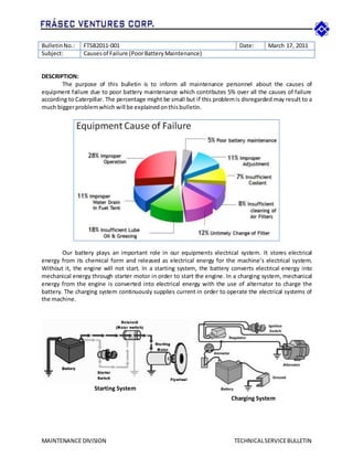
1. MAINTENANCE DIVISION TECHNICALSERVICEBULLETIN
BulletinNo.: FTSB2011-001 Date: March 17, 2011
Subject: Causesof Failure (PoorBatteryMaintenance)
DESCRIPTION:
The purpose of this bulletin is to inform all maintenance personnel about the causes of
equipment failure due to poor battery maintenance which contributes 5% over all the causes of failure
according to Caterpillar. The percentage might be small but if this problemis disregarded may result to a
much biggerproblemwhich will be explainedonthisbulletin.
Our battery plays an important role in our equipments electrical system. It stores electrical
energy from its chemical form and released as electrical energy for the machine’s electrical system.
Without it, the engine will not start. In a starting system, the battery converts electrical energy into
mechanical energy through starter motor in order to start the engine. In a charging system, mechanical
energy from the engine is converted into electrical energy with the use of alternator to charge the
battery. The charging system continuously supplies current in order to operate the electrical systems of
the machine.
Starting System
Charging System
2. MAINTENANCE DIVISION TECHNICALSERVICEBULLETIN
Most of our Caterpillar units are
controlled by ECM (Electronic Control Module).
An enclosed computer that is used to control the
equipment’s operation both engine and hydraulic
systems. The other function of an ECM is to
gather data for technical analysis when
diagnosed by CAT ET. It also controls the EMS
(Electronic Monitoring System) which serves as
an indicator to alarm the operator about the
currentstatus inreal time.
ECM works by analyzing input signals
from various sensors installed on the different
systems of the machine. The machine ECM
continuously monitors these input signals in order to control the output flow rate of the hydraulic
pumps, engine speed, fuel injection etc. The ECM sends output signals to energize solenoid valves,
relays,sensors andotherelectronicaccessories.
As a computer, the ECMprocess information through digital signal and analog signals. It supplies
5.0 ± 0.2 VDC to most sensors and a regulated voltage supply of 8.0 ± 0.4 VDC to the speed/timing
sensors to calculate engine rpm. And because of these parameters, our unit’s electronic systems are
sensitiveenoughtocertain variationof voltage.
A voltage fluctuation takes place when a battery kicks to a certain degree of voltage increase
due to instantaneous contact between positive and negative poles of the battery in which a spark
(electric arc) is mostly created between battery terminals and clamps (can also be found on connectors).
And since our equipment operates at 24 VDC, our battery is powerful enough to produce voltage that is
destructive toourelectroniccircuitry.
OBSEVATIONS AND FINDINGS:
AfterCATET Diagnosticswasperformedtoall Caterpillarunits,itwasfoundthatthere are numerous
error codesloggeddue topoor batterymaintenance.
To name a few,the followingeffectsare listedbelow;
168-5 : Electrical SystemVoltage–CurrentBelow Normal
168-1 : Electrical SystemVoltage–Low
246-9 : ProprietaryCAN DataLink - Abnormal Update Rate
269-4 : SensorPowerSupply –Voltage Below Normal
588-9 : MonitoringSystemDisplay –Abnormal Update Rate
590-9 : Engine Control Module –Abnormal Update Rate
41-6 : 8 VoltDC Supply – CurrentAbove Normal
3. MAINTENANCE DIVISION TECHNICALSERVICEBULLETIN
The followingphotos are actual batteryinstallationfoundduringinspectionof units.
D8N Battery compartment and a closed up view of the battery showing a damaged terminal due to
loose clamping which have cause spark within its terminal area.
A battery clamp of BH-05 Corroded battery clamp
A disconnect switch with a welding rod engaged
to switch it on
The batteries without the fixture cover
4. MAINTENANCE DIVISION TECHNICALSERVICEBULLETIN
Battery grounding of D5M A Positive cable loosely attached to the clamp
BEST PRACTICE:
In response to correct or prevent recurrence of these failures, we recommend the following Best
Practice to be followedinordertoperformmaintenance proceduressuccessfully.
1. Strictlyimplementoperator’swalkaroundinspectionunderBLOWAF;
a. Checkbatterycables,itshould be tightlyboltedtothe clamp
b. Inspectclampsforcorrosions
c. Checkbatteryterminalsforcracks
d. Batteryfixturesmustbe inplacedtopreventmovementcausedbyvibration&swing
2. Use disconnectkeytoturnon/off the disconnectswitch (notweldingrod).
3. Disconnectswitchmustbe turnedoff aftermachine isparkedandremove key.
4. Use jumpstartcablesif batteryinstalledisdrained.
5. Refrainontransferringbatteriesfromone unittoanother.
6. Be sure to replace the batterywithanotherbatterythatisequal incapacityto the original.
There are many positive impacts associated with this Best Practice. Such positive impacts may
include: improved equipment reliability, maintenance and repair efficiency, high mechanical availability,
and improved mining operation performance. The impact of improving our battery management may
leadto greatersavingsonour equipment costresultingtogreaterproductivity andrevenue.
Preparedby:
Maximo V. Ginez III
Maintenance Planner
Notedby:
Chanito L. Ouano
Maintenance Division Head
Approvedby:
Francis Gerard S. Cañedo
President