Download to read offline


![FRONT COIL SPRING AND SHOCK ABSORBER
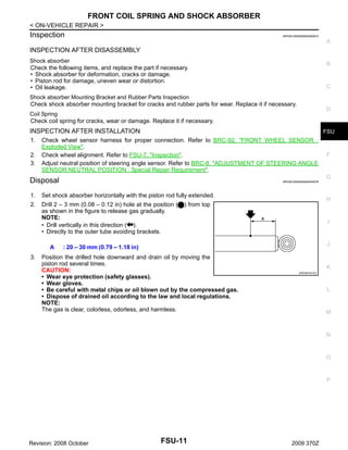
< ON-VEHICLE REPAIR >
1. Install shock absorber attachment (A) [SST: ST35652000 ( –
)] to shock absorber and secure it in a vise.
CAUTION:
When installing the shock absorber attachment to shock
absorber, wrap a shop cloth around shock absorber to protect it from damage.
A
B
C
JPEIA0006ZZ
D
2.
3.
4.
5.
6.
Using a spring compressor (A) (commercial service tool), compress coil spring between rubber seat and shock absorber until
coil spring with a spring compressor is free.
CAUTION:
Be sure a spring compressor is securely attached coil
spring. Compress coil spring.
Remove piston rod lock nut while securing the piston rod tip so
that piston rod does not turn.
CAUTION:
Make sure coil spring with a spring compressor between
rubber seat and shock absorber is free.
JPEIA0168ZZ
Remove mounting seal, shock absorber mounting bracket, rubber seat, bound bumper from shock absorber.
After remove coil spring with a spring compressor, and then gradually release a spring compressor.
CAUTION:
Loosen while making sure coil spring attachment position does not move.
Remove the shock absorber attachment from shock absorber.
FSU
F
G
H
I
ASSEMBLY
1.
2.
Install shock absorber attachment [SST: ST35652000 ( – )] to shock absorber and secure it in a vise.
CAUTION:
When installing the shock absorber attachment to shock absorber, wrap a shop cloth around
shock absorber to protect it from damage.
Compress coil spring using a spring compressor (commercial service tool), and install it onto shock
absorber.
CAUTION:
• Install with the large-diameter side (A) facing up and the
small-diameter side (B) facing down.
• Be sure a spring compress or is securely attached to coil
spring. Compress coil spring.
J
K
L
M
N
O
PEIA0108E
P
Revision: 2008 October
FSU-9
2009 370Z](https://image.slidesharecdn.com/fsu-140302061224-phpapp01/85/Fsu-9-320.jpg)


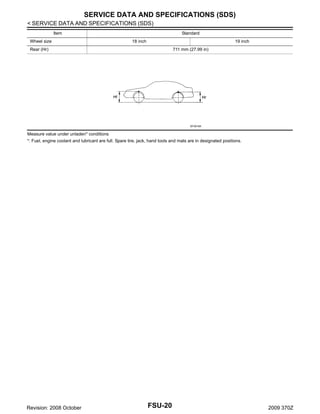
![TRANSVERSE LINK
< ON-VEHICLE REPAIR >
Before measurement, move ball stud at least ten times by hand to check for smooth movement.
1. Move the ball joint at least ten times by hand to check for smooth movement.
2. Hook a spring balance (A) at cotter pin mounting hole. Confirm
spring balance measurement value is within specifications when
ball stud begins moving.
Standard
Swing toque
A
B
C
: Refer to FSU-19, "Ball
Joint".
• If swing torque exceeds standard range, replace transverse link
assembly.
D
JPEIA0005ZZ
Rotating Torque Inspection
1.
2.
FSU
Move the ball joint at least ten times by hand to check for smooth movement.
Attach mounting nut to ball stud. Make sure that rotating torque
is within specifications with a preload gauge (A) [SST:
ST3127S000 (J-25765-A)].
Standard
Rotating toque
F
G
: Refer to FSU-19, "Ball
Joint".
H
• If rotating torque exceeds standard range, replace transverse link
assembly.
PDIA1258E
I
Axial End Play Inspection
1.
2.
Move the ball joint at least ten times by hand to check for smooth movement.
Move tip of ball stud in axial direction to check for looseness.
Standard
Axial end play
J
: Refer to FSU-19, "Ball
Joint".
K
• If axial end play exceeds standard range, replace transverse link assembly.
L
INSPECTION AFTER INSTALLATION
1.
2.
3.
Check wheel sensor harness for proper connection. Refer to BRC-92, "FRONT WHEEL SENSOR :
Exploded View".
Check wheel alignment. Refer to FSU-7, "Inspection".
Adjust neutral position of steering angle sensor. Refer to BRC-8, "ADJUSTMENT OF STEERING ANGLE
SENSOR NEUTRAL POSITION : Special Repair Requirement".
M
N
O
P
Revision: 2008 October
FSU-13
2009 370Z](https://image.slidesharecdn.com/fsu-140302061224-phpapp01/85/Fsu-13-320.jpg)


The document provides instructions for servicing the front suspension of a vehicle. It includes exploded views and procedures for removal and installation of various front suspension components like the front coil spring, shock absorber, transverse link, upper link, front stabilizer, and tower bar. Safety precautions are provided for working with airbags and during the suspension repair process. Inspection instructions are given for the front suspension assembly, wheel alignment, and individual components.