AIM
To learn theprimary functions, Components and
systems of FMS
10.
OBJECTIVE
By the endof this lesson the pupil should able to:-
Flight Management Guidance Systems.
Electronic Flight Instrument Systems.
Electronic Centralised Aircraft Monitor
11.
TIE IN ANDREVISION
Management System
Sortie Calculation
Performance Calculation
12.
INTRODUCTION
Increasing AirTravel and therefore Air traffic and thus
increased word load to be executed in limited time
In such a situation, a system which can automatically
track all activities and assist the operator in taking
decisions is desirable.
Flight Management system
13.
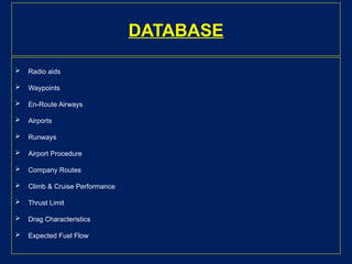
FMS
Flight Management Systemis a pilot interactive and
nav computing and display system designed to assist in
flying an aircraft with maximum economy and safety to a
previously planned route defined both vertically and
laterally
SYSTEM COMPONENTS
(a) Sensors
(b)Processors or Computer Sub-systems
(i) Caution and Warning System
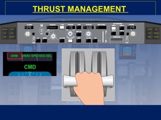
(ii) Thrust Management
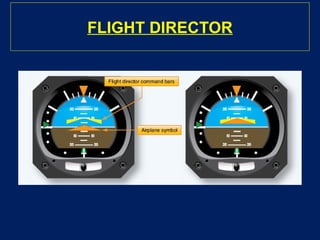
(iii) Autopilot/Flight Director System
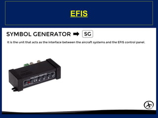
(iv) Electronic Flight Instrument Symbol Generator
(c) Cockpit Control & Display Unit
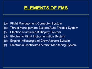
ELEMENTS OF FMS
(a)Flight Management Computer System
(b) Thrust Management System/Auto Throttle System
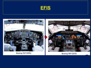
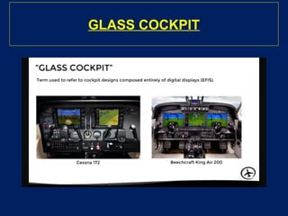
(c) Electronic Instrument Display System
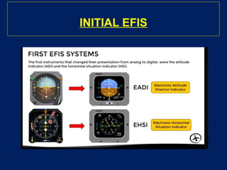
(d) Electronic Flight Instrumentation System
(e) Engine Indicating and Crew Alerting System
(f) Electronic Centralized Aircraft Monitoring System
28.
FMCS
Preparation offlight plans (diversion to alternate A/F) synthesis of nav
information (all available sources)
Automatic frequency selection and tuning of nav aids
Lateral guidance
Optimization of flight path in the vertical plane Guidance in vertical
plane
Prediction of flight parameters (along a/c route)
Display management (EFIS/EICAS/ECAMS)
ELEMENTS
Three groups ofkeys are there:
Function Keys
Alphanumeric Keys : To select the display. To enter the
data.
Line Keys : For crew interaction with the displays.
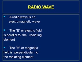
RADIO WAVE
Aradio wave is an
electromagnetic wave
The "E" or electric field
is parallel to the radiating
element
The ”H" or magnetic
field is perpendicular to
the radiating element
56.
NON DIRECTIONAL BEACON
Ground based radio
station
Radiate equally in all
direction
Amplitude modulated
Vertically Polarized
signal
ADF
Automatic DirectionFinder finds the direction
of ground based beacon called the NDB or non
directional beacon
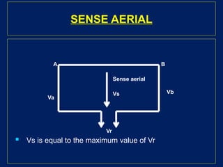
ADF aerial comprises of Loop and Sense
aerial, indicator and control unit
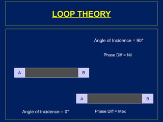
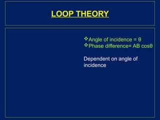
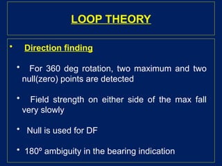
LOOP THEORY
• Directionfinding
• For 360 deg rotation, two maximum and two
null(zero) points are detected
• Field strength on either side of the max fall
very slowly
• Null is used for DF
• 180º ambiguity in the bearing indication
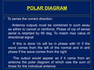
POLAR DIAGRAM
Tosense the correct direction:
•Antenna outputs must be combined in such away
as either to cancel or reinforce. Phase of o/p of sense
aerial is retarded by 90 deg. To match max value of
directional signal
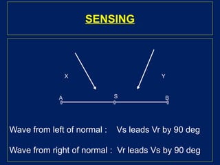
•If this is done Vs will be in phase with Vr if the
wave comes from the left of the normal and in anti
phase if the wave comes from the right
•The output would appear as if it came from an
antenna the polar diagram of which was the sum of
those for the individual antenna
74.
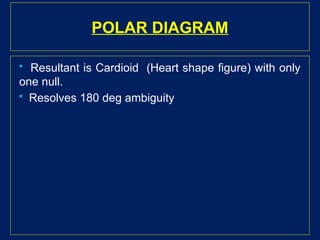
POLAR DIAGRAM
Resultantis Cardioid (Heart shape figure) with only
one null.
Resolves 180 deg ambiguity
75.
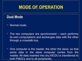
MODE OF OPERATION
DualMode
Normal mode.
The two computers are synchronized – each performs
its own computations and exchanges data with the other
through a crosstalk bus.
One computer is the master, the other the slave, so that
some data in the slave computer comes from the
master. All data inserted into any MCDU is transferred to
both FMGCs and to all peripherals
76.
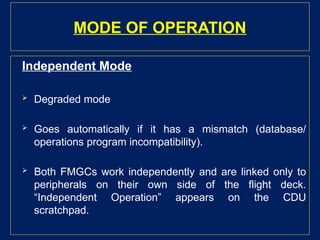
MODE OF OPERATION
IndependentMode
Degraded mode
Goes automatically if it has a mismatch (database/
operations program incompatibility).
Both FMGCs work independently and are linked only to
peripherals on their own side of the flight deck.
“Independent Operation” appears on the CDU
scratchpad.
77.
MODE OF OPERATION
SingleMode
The system selects this mode automatically if
one FMGC fails. The other FMGC drives all the
peripherals. When one FMGC fails, the
corresponding CDU displays failure indication