The document provides an overview of the Fluke 1750 Power Recorder system including:
- Key features such as wireless control via PDA and automatic disturbance capture
- Safety information and standard accessories
- Instructions for contacting Fluke for support


![www.netzerotools.com
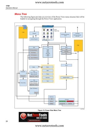
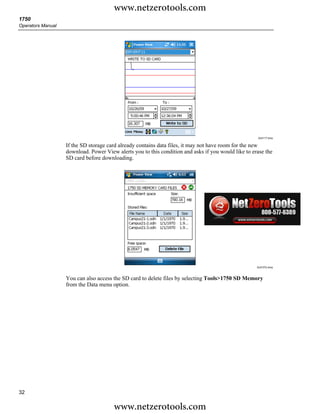
1750
Operators Manual
Table 1. Symbols
Symbol Meaning Symbol Meaning
Hazardous voltage. Risk of electrical Risk of danger. Important information.
X shock.
W See manual.
Conforms to requirements of European Do not dispose of this product as
P Union and European Free Trade ~ unsorted municipal waste. Contact Fluke
Association (EFTA). or a qualified recycler for disposal.
Canadian Standards Association.
) [Note: Canadian and US.]
J Protective conductor terminal.
CAT III equipment is designed to
CAT IV equipment is designed to protect
protect against transients in equipment
against transients from the primary
in fixed-equipment installations, such
CAT III CAT IV supply level, such as an electricity meter
as distribution panels, feeders and
or an overhead or underground utility
short branch circuits, and lighting
service.
systems in large buildings.
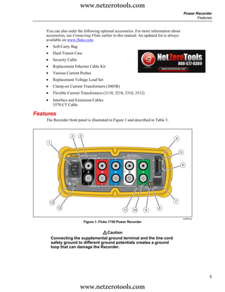
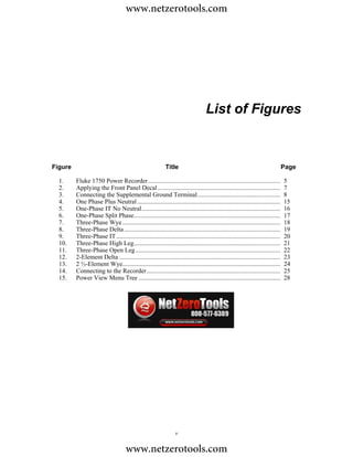
Accessories
Table 2 describes the standard accessories that ship with the Recorder.
Table 2. Standard Accessories
Description Part Number
Ethernet cable, 3 meters, yellow 2402854
Colored plastic clips for test leads (32 clips, 8 colors, 4 clips each color) 2157607
Model TLS430, test lead set including cable and clips 2157713
Secure Digital (SD) Memory Card for downloading data Call for details
Model 3140R, 400 A Clamps (4-not included with Basic version) 2277216
AC power cord, 3 meters 2441360
Personal Digital Assistant (PDA) with USB cable and accessories 2386780
CD-ROM Manuals and Software 2386771
1750 Getting Started Guide 2386767
Sheet of Front Panel Decals 2436261
Sets of international ac power plug adapters for the PDA charger 2583479
International adapters for the Recorder power cord 2441372
4
www.netzerotools.com](https://image.slidesharecdn.com/fluke-1750-owners-manual-u-13355631304-u-120427164535-phpapp01/85/Fluke-1750-Manual-12-320.jpg)