Download as PDF, PPTX


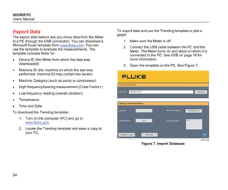
![805/805 FC
Users Manual
40
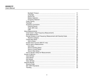
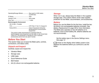
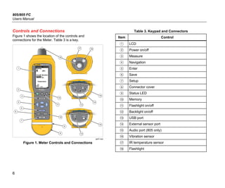
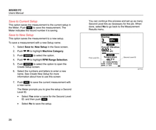
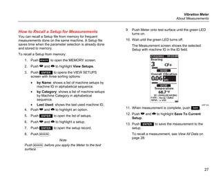
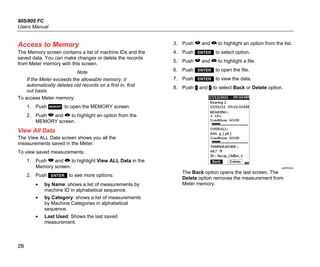
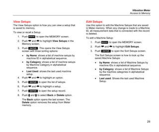
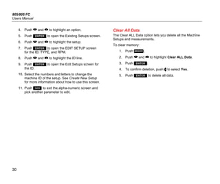
How to Troubleshoot
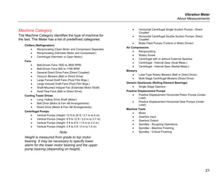
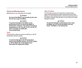
Table 8 is a list of problems, causes, and corrective actions for the Meter.
Table 8. Troubleshooting
Symptom Cause Corrective Action
Meter does not turn on. • The battery voltage is too
low.
• The battery connection is
loose.
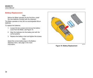
1. Replace the batteries. See Battery Replacement on
page 38 for more information.
2. Ensure the batteries are properly aligned and
secured.
3. If the problem continues, contact the Fluke Service
Center [1]
for technical support.
Buttons do not operate. Meter
does not operate.
1. Restart the Meter.
2. If the problem continues, contact the Fluke Service
Center [1]
for technical support.
The Meter cannot connect with
the PC.
The USB cable is not
connected correctly.
Correctly connect the USB cable. See USB on page 16 for
more information.
• The USB cable is
damaged.
• Check that USB drivers
are installed in the
PC/Laptop.
1. Examine the USB cable for any damage. If you find
damage, contact the Fluke Service Center [1]
for a
replacement cable.
2. Reboot the PC.
PC does not see the Meter is
connected.
Reboot the PC.
Error Message: Measurement
invalid. Please hold to surface
for full duration.
The Meter was not held on
the surface for a sufficient
time or with sufficient force.
Push Meter onto test surface until green LED turns on.
Wait until the green LED turns off. See About
Measurements on page 17 for more information.
[1] See How to Contact Fluke on page 1.](https://image.slidesharecdn.com/805umeng0200-190603033805/85/H-ng-d-n-s-d-ng-Fluke-805-50-320.jpg)

The document provides a limited warranty and liability terms for Fluke products: 1. Fluke warrants its products to be free from defects in material and workmanship for one year from the date of shipment. Parts, repairs, and services are warranted for 90 days. 2. The warranty is limited to the original buyer and does not cover misuse, abuse, or modifications to the product. Software is warranted to operate as specified for 90 days. 3. Fluke's sole obligation is to repair, replace, or refund the purchase price of defective products returned within the warranty period. Consequential damages are excluded from the warranty.


