1
Fluid
Definition
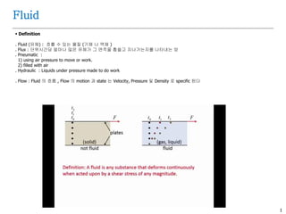
. Fluid(유체) : 흐를 수 있는 물질 (기체 나 액체 )
. Flux : 단위시간당 얼마나 많은 유체가 그 면적을 휩쓸고 지나가는지를 나타내는 양
. Pneumatic :
1) using air pressure to move or work.
2) filled with air
. Hydraulic : Liquids under pressure made to do work
. Flow : Fluid 의 흐름 , Flow 의 motion 과 state 는 Velocity, Pressure 및 Density 로 specific 된다
3.
2
Fluid
Compressible VSIncompressible
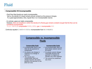
. Fluid Flow Most liquids are nearly incompressible;
that is, the density of a liquid remains almost constant as the pressure changes.
To a good approximation, then, liquids flow in an incompressible manner.
. In contrast, gases are highly compressible.
However, there are situations in which the density of a flowing gas remains constant enough that the flow can be
considered incompressible.
가스는 기본적으로 compressible 이지만, 흐르는 gas 는 incompressible 이다
. Continuity equation 과 베르누이 정리는 incompressible fluid 에 만 해당한다
4.
3
Flow
Type ofFlow Profile
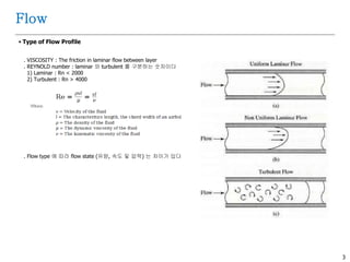
. VISCOSITY : The friction in laminar flow between layer
. REYNOLD number : laminar 와 turbulent 를 구분하는 숫자이다
1) Laminar : Rn < 2000
2) Turbulent : Rn > 4000
. Flow type 에 따라 flow state (유량, 속도 및 압력) 는 차이가 있다
5.
4
Fluid
Viscosity
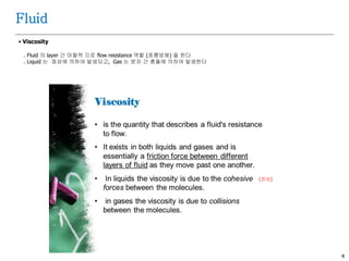
. Fluid의 layer 간 마찰력 으로 flow resistance 역할 (흐름방해) 을 한다
. Liquid 는 점성에 의하여 발생되고, Gas 는 분자 간 충돌에 의하여 발생한다
(점성)
6.
5
Fluid
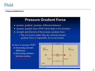
PRESSURE GRADIENT
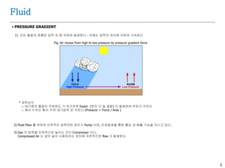
1)모든 물질의 흐름은 압력 차 에 의하여 발생한다 : 유체는 압력의 차이에 의하여 가속된다
Fig. Air moves from high to low pressure by pressure gradient force
* 과학상식
-. 대기중의 물질이 주변온도 가 차가우면 fusion (분자 간 밀 결합) 이 발생하여 부피가 커진다
-. 해서 누르는 힘이 커져 대기압력 은 커진다 (Pressure = Force / Area )
2) Fluid Flow 를 위하여 인위적인 압력저하 장치가 Pump 이며, 진공발생을 통한 흡입 과 배출 기능을 지니고 있다.
3) Gas 의 압력을 인위적으로 높이는 것이 Compressor 이다.
Compressed Air 는 압이 높아 사용하려는 장치에 자연적으로 flow 가 발생한다
7
Flow
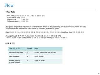
Flow Rate
.Flow Rate 은 아래와 같이 세가지 구분으로 정량화 된다
1) Volumetric Flow : 유량
2) Mass Flow : 질량유량
3) Average Velocity : 평균유속
. For gases, temperature and pressure have significant effects on the gas density, and thus on the volumetric flow rate,
so mass flow rate is sometimes used instead of volumetric flow rate for gases.
. Gas 와 같은 경우는, 온도와 압력에 영향을 주요하게 받음으로, 특정한 경우에는 Mass Flow Rate 으로 정량화 한다
. Average Velocity 를 측정하여, Volumetric Flow 를 산출 하는데 사용한다 (Q=VA)
우리가 흔히 사용하는 Flow meter 및 피토관 은 Average Velocity 를 구하는데 사용한다
. 심볼 및 단위
Flow 정량화 구분 Symbol Units
Volumetric Flow Rate Q ft3/sec, gallons per min, m3/sec
Mass Flow Rate m lb/hr, kg/min
Average Velocity
(Linear Velocity)
V ft/sec or m/sec
9.
8
Flow
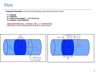
Volumetric FlowRate : the volume of fluid passing a point along the tube per second
. v = Velocity
. d = Distance
. A = Area (cross-section) , 단면적 (3.14*r2)
. V = Volume = Area*Distance
. Volume Flow Rate (Q) = Volume / Time == Velocity*Area
. 특정지점에서 단위시간 (1초) 당 특정면적 을 흐르는 량 을 나타낸다
10.
9
Flow
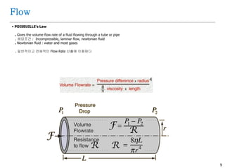
POISEUILLE’s Law
.Gives the volume flow rate of a fluid flowing through a tube or pipe
. 해당조건 : Incompressible, laminar flow, newtonian fluid
. Newtonian fluid : water and most gases
. 일반적이고 전체적인 Flow Rate 산출에 이용된다
11.
10
Flow
POISEUILLE’s Law
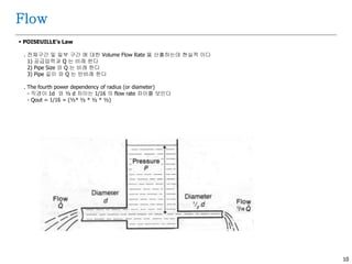
.전체구간 및 일부 구간 에 대한 Volume Flow Rate 을 산출하는데 현실적 이다
1) 공급압력과 Q 는 비례 한다
2) Pipe Size 와 Q 는 비례 한다
3) Pipe 길이 와 Q 는 반비례 한다
. The fourth power dependency of radius (or diameter)
- 직경이 1d 와 ½ d 차이는 1/16 의 flow rate 차이를 보인다
- Qout = 1/16 = (½ * ½ * ½ * ½ )
12.
11
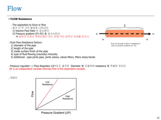
FLOW Resistance
.The opposition to force or flow
. 증가 시 두 가지 결과로 나타난다
1) Volume Flow Rate 이 감소한다
2) Pressure gradient (P1-P2) 를 감소시킨다
압력의 저하는 특정지점이 아닌 전체 적인 압력의 저하를 보인다
. Fluid Flow Resistance factors:
1) diameter of the pipe
2) length of the pipe
3) inside surface finish of the pipe
4) type of fluid flowing (viscosity) Viscosity
5) Additional : pipe joints pipe, joints valves, valves filters, filters sharp bends
. Pressure regulator 나 Flow Regulator (밸브) 도 결국은 Diameter 를 조절하여 resistance 를 적용한 것이다
ΔP is an independent variable whereas flow is the dependent variable.
. 개념도
Flow
13.
12
FLOW Resistance
.예1. 관내의 막힘(돌기) 에 의한 Flow Rate 예
. 예2. : Flow resistance 는 100cm*5 보다, 1cm*1 이 6.25배 많다 = 5의4승 / 100
Flow
14.
13
Flow
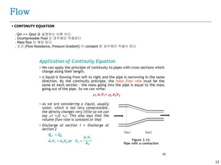
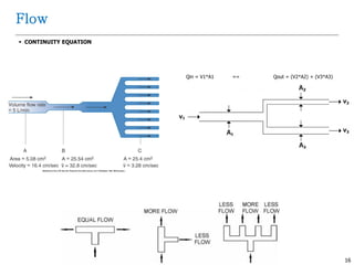
CONTINUTY EQUATION
.Qin == Qout 을 설명하는 이론 이다
. Incompressible Fluid 인 경우에만 적용된다
. Mass flow 만 해당 된다
. 조건 (Flow Resistance, Pressure Gradient) 이 constant 한 경우에만 적용이 된다
15.
14
Flow
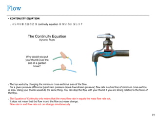
CONTINUITY EQUATION
.수도꼭지를 조절하면 왜 continuity equation 에 해당 하지 않는가 ?
. The tap works by changing the minimum cross-sectional area of the flow.
For a given pressure difference (upstream pressure minus downstream pressure) flow rate is a function of minimum cross-section
al area. Using your thumb would do the same thing. You can stop the flow with your thumb if you are strong relative to the force of
the flow.
. The Equation of Continuity only means that the mass flow rate in equals the mass flow rate out.
It does not mean that the flow in and the flow out never change.
Flow rate in and flow rate out can change simultaneously
16.
15
Flow
CONTINUITY EQUATION
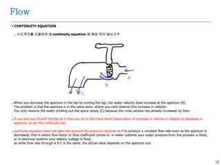
.수도꼭지를 조절하면 왜 continuity equation 에 해당 하지 않는가 ?
. When you decrease the aperture in the tap by turning the tap, the water velocity does increase at the aperture (B).
The problem is that the aperture is in the valve stem, where you cant observe this increase in velocity.
You only observe the water trickling out the spout slowly (C) because the cross section has already increased by then.
. If you put your thumb directly at C then you do in fact have direct observation of increase in velocity in relation to decrease in
aperture, as per the continuity law.
. continuity equation does not take into account the pressure required at A to produce a constant flow rate even as the aperture is
decreased. that is where flow factor or flow coefficient comes in. in water systems your water pressure from the provider is fixed,
or in electrical systems your battery voltage is fixed.
so while flow rate through A B C is the same, the actual value depends on the aperture size.
17
Pressure
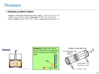
PRESSURE byKINETIC ENERGY
. Pressure = Force Per Unit Area (P= Force / Area) , 단위면적에 가해지는 힘
. 밀폐된 공간에 존재하는 물질의 (Molecule) 운동 에너지에 의하여 발생
. 물질의 mobility 성질에 의하여 벽과 의 충돌 시 bounce off 될때 발생되는 힘
19.
18
Pressure
압력관련 법칙
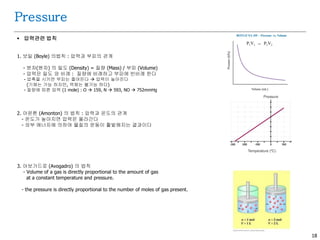
1.보일 (Boyle) 의법칙 : 압력과 부피의 관계
- 분자(원자) 의 밀도 (Density) = 질량 (Mass) / 부피 (Volume)
- 압력은 밀도 와 비례 : 질량에 비례하고 부피에 반비례 한다
- 압축을 시키면 부피는 줄어든다 압력이 높아진다
(기체는 가능 하지만, 액체는 불가능 하다)
- 질량에 따른 압력 (1 mole) : O 159, N 593, NO 752mmHg
2. 아몬톤 (Amonton) 의 법칙 : 압력과 온도의 관계
- 온도가 높아지면 압력은 올라간다
- 외부 에너지에 의하여 물질의 운동이 활발해지는 결과이다
3. 아보가드로 (Avogadro) 의 법칙
- Volume of a gas is directly proportional to the amount of gas
at a constant temperature and pressure.
- the pressure is directly proportional to the number of moles of gas present.
20.
19
Pressure
압력관련 법칙
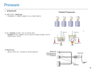
4.달톤의 법칙 : Partial Law
- 전체질량은 각 개별적인 물질이 지니는 질량의 합이다
5. 찰스 (Charles) 의 법칙 : 온도 와 부피의 관계
- Constant 한 압력 상황에서 온도과 높아지면 동일한 압력을 가져가기
위하여 부피가 커진다
6. Pascal’s Law
. 폐쇠된 내부의 어느 위치에서도 압력은 동일하다
21.
20
압력 과Density (밀도) 관계
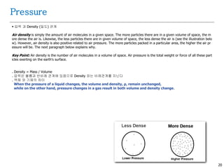
Air density is simply the amount of air molecules in a given space. The more particles there are in a given volume of space, the m
ore dense the air is. Likewise, the less particles there are in given volume of space, the less dense the air is (see the illustration belo
w). However, air density is also positive related to air pressure. The more particles packed in a particular area, the higher the air pr
essure will be. The next paragraph below explains why.
Key Point: Air density is the number of air molecules in a volume of space. Air pressure is the total weight or force of all these part
icles exerting on the earth's surface.
. Density = Mass / Volume
. 압력은 볼륨과 반비례 관계에 있음으로 Density 와는 비례관계를 지닌다
. 액체 와 기체의 차이
When the pressure of a liquid changes, the volume and density, ρ, remain unchanged,
while on the other hand, pressure changes in a gas result in both volume and density change.
Pressure
22.
21
Pressure
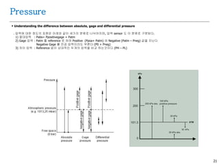
Understanding thedifference between absolute, gage and differential pressure
. 압력에 대한 정도의 표현은 아래와 같이 세가지 분류로 나뉘어지며, 압력 sensor 도 이 분류로 구분된다.
1) 절대압력 : Pabs= Ppositivegage + Patm
2) Gage 압력 : Patm 를 reference 로 하며 Positive (Ppoa+ Patm) 와 Negative (Patm – Pneg) 값을 지닌다
Negative Gage 를 진공 압력이라도 부른다 (P0 + Pneg)
3) 차이 압력 : Reference 없이 상대적인 두개의 압력을 비교 하는것이다 (PH – PL)
23.
22
Pressure
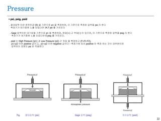
psi, psig,psid
. 절대압력 이란 완전진공 (0) 을 기준으로 p1 을 측정하며, 이 기준으로 측정된 압력을 psi 라 한다
측정기가 대기중에 노출 되었다면 14.7 psi 를 가르킨다
. Gage 압력이란 대기압을 기준으로 p1 을 측정하며, 정압(+) 고 부압(-) 이 있으며, 이 기준으로 측정된 압력을 psig 라 한다
측정기가 대기중에 노출 되었다면 0 psig 를 가르킨다.
. psid 는 High Pressure (p1) 과 Low Pressure (p2) 간 차압 을 측정하고 (F=F1-F2),
p1>p2 이면 positive 값이고, p1<p2 이면 negative 값이다 - 측정기에 따라 positive 만 측정 하는 것이 대부분이며
압력차이 표현도 psi 로 적용한다
Fig. 절대압력 (psi) Gage 압력 (psig) 차이압력 (psid)
24
Pressure
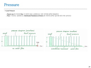
Local Pressure
.Pascal Law 에 의하여 flow 가 흐르지 않는 상태에서는 모든 부위에 압력은 동일하다
. Flow 가 흐르는 상태에서는 Distributed Resistance (friction) 에 의하여 압력은 길이에 따라가며 낮아진다
26.
25
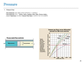
Pressure Drop
.Flow Restrictor 장치 들에 의하여 압력저하 가 발생된다
. Flow Restrictor 장치 : Orifice, Valve, Capillary tube, Filter, Porous metal,,,
. 동일한 Restriction 조건에서 Volume Flow Rate 는 압력의 차이 와 비례한다
Pressure
27.
26
Pressure
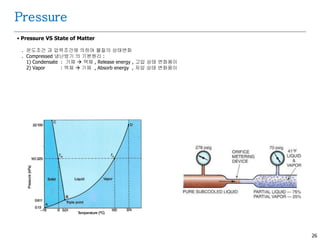
Pressure VSState of Matter
. 온도조건 과 압력조건에 의하여 물질의 상태변화
. Compressed 냉난방기 의 기본원리 :
1) Condensate : 기체 액체 , Release energy , 고압 상태 변화용이
2) Vapor : 액체 기체 , Absorb energy , 저압 상태 변화용이
28.
27
Dew Point
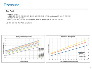
.Dew Point (이슬점)
- HO2 물질이 주변의 온도에 의하여 물질의 상태변화 (기체 액체, condensate) 가 되는 주변온도 점
- 상대습도에 따라 달라진다
- Stack 내의 샘플가스 분석을 위하여 Heated probe 및 Heated tube 를 사용하는 기본원리
. 압력이 높아지면 Dew Point 도 높아진다
Pressure
29.
28
Pressure
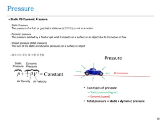
Static VSDynamic Pressure
. Static Pressure
The pressure of a fluid or gas that is stationary (정지된) or not in a motion
. Dynamic pressure
The pressure exerted by a fluid or gas whet it impacts on a surface or an object due to its motion or flow
. Impact pressure (total pressure)
The sum of the static and dynamic pressures on a surface or object
. 베르누이 정리 에 의한 이론화
30.
29
요약
. 요약
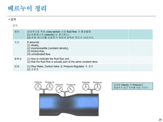
베르누이정리
정의 상대적으로 작은 cross section 으로 fluid flow 가 통과할때
(1) 운동에너지 (velocity) 는 증가한다.
(2) 전체 에너지를 보존하기 위하여 압력은 반드시 내려간다.
조건 It assumes
(1) steady,
(2) incompressible (constant density),
(3) friction-free,
(4) unmotivated flow.
불확실 (1) how to motivate the fluid flow and
(2) that the fluid flow is actually part of the same constant-dens
응용 (1) Flow Meter, Control Valve 및 Pressure Regulator 의 원리
(2) 피토관
실제로 Velocity 와 Pressure는
동일하지 않고 저하를 보일 것이다
31.
30
요약
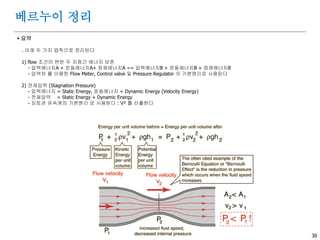
. 아래두 가지 법칙으로 정리된다
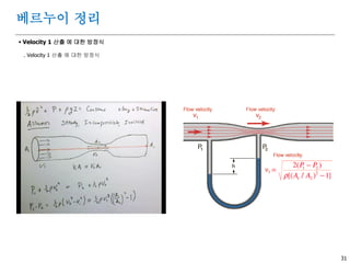
1) flow 조건이 변한 두 지점간 에너지 보존
- 압력에너지A + 운동에너지A+ 잠재에너지A == 압력에너지B + 운동에너지B + 잠재에너지B
- 압력차 를 이용한 Flow Meter, Control valve 및 Pressure Regulator 의 기본원리로 사용된다
2) 전체압력 (Stagnation Pressure)
- 압력에너지 = Static Energy, 운동에너지 = Dynamic Energy (Velocity Energy)
- 전체압력 = Static Energy + Dynamic Energy
- 피토관 유속계의 기본원리 로 사용된다 : V² 를 산출한다
베르누이 정리
32
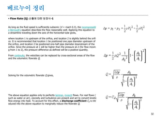
Flow Rate(Q) 산출에 대한 방정식-1
As long as the fluid speed is sufficiently subsonic (V < mach 0.3), the incompressibl
e Bernoulli's equation describes the flow reasonably well. Applying this equation to
a streamline traveling down the axis of the horizontal tube gives,
where location 1 is upstream of the orifice, and location 2 is slightly behind the orifi
ce. It is recommended that location 1 be positioned one pipe diameter upstream of
the orifice, and location 2 be positioned one-half pipe diameter downstream of the
orifice. Since the pressure at 1 will be higher than the pressure at 2 (for flow movin
g from 1 to 2), the pressure difference as defined will be a positive quantity.
From continuity, the velocities can be replaced by cross-sectional areas of the flow
and the volumetric flowrate Q,
Solving for the volumetric flowrate Q gives,
The above equation applies only to perfectly laminar, inviscid flows. For real flows (
such as water or air), viscosity and turbulence are present and act to convert kinetic
flow energy into heat. To account for this effect, a discharge coefficient Cd is intr
oduced into the above equation to marginally reduce the flowrate Q,
베르누이 정리
34.
33
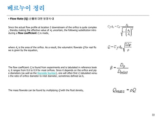
Flow Rate(Q) 산출에 대한 방정식-2
Since the actual flow profile at location 2 downstream of the orifice is quite complex
, thereby making the effective value of A2 uncertain, the following substitution intro
ducing a flow coefficient Cf is made,
where Ao is the area of the orifice. As a result, the volumetric flowrate Q for real flo
ws is given by the equation,
The flow coefficient Cf is found from experiments and is tabulated in reference book
s; it ranges from 0.6 to 0.9 for most orifices. Since it depends on the orifice and pip
e diameters (as well as the Reynolds Number), one will often find Cf tabulated versu
s the ratio of orifice diameter to inlet diameter, sometimes defined as b,
The mass flowrate can be found by multiplying Q with the fluid density,
베르누이 정리
35.
34
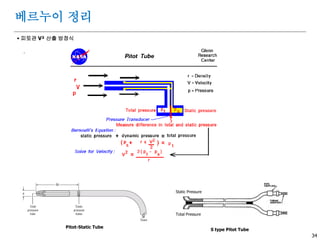
피토관 V²산출 방정식
.
베르누이 정리
Pitot-Static Tube
S type Pitot Tube
Total Pressure
Static Pressure
36
Application : ControlValve
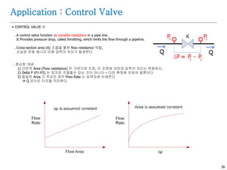
CONTROL VALVE 란
. A control valve function as variable resistance in a pipe line.
It Provides pressure drop, called throttling, which limits the flow through a pipeline.
. Cross-section area (A) 조절을 통한 flow resistance 역할,
손실된 운동 에너지 만큼 압력의 차이가 발생한다
. 중요한 개념
1) 단면적 Area (Flow resistance) 만 가변으로 조정, 이 조정에 의하여 압력의 차이는 변화된다.
2) Delta P (P1-P2) 는 임의로 조절할수 있는 것이 아니다 – 다만 측정에 의하여 알뿐이다
3) 동일한 Area 가 주어진 경우 Flow Rate 는 압력차에 비례한다
Q 공식은 이것을 의미한다
38.
37
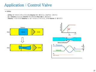
Orifice
. Orifice에 의하여 단위시간당 (초) Volume 량이 줄어드는 개념적인 그림이다
. Q = Volume / t 임으로 Volume 에 비례하여 Flow rate 도 줄어든다
. Velocity 가 증가되면 Distance 는 증가 되었다고 하더라도, 전체 Volume 은 줄어든다
Application : Control Valve
FLOWVolumeArea
Distance
FLOWArea Volume
39.
38
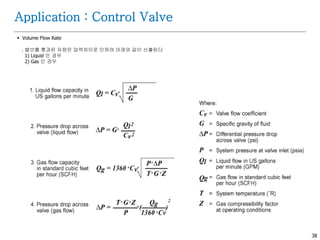
Volume FlowRate
. 밸브를 통과된 유량은 압력차이로 인하여 아래와 같이 산출된다
1) Liquid 인 경우
2) Gas 인 경우
Application : Control Valve
40.
39
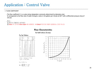
FLOW COEFFICENT
.The flow coefficient Cv is a valve sizing designation commonly determined by laboratory test.
It corresponds to the flow rate of water through a valve in US gallons per minute at 60°F with a differential pressure drop of
one psi.
. 중요 :
1) 제조사 모델마다 상이하다
2) Valve 의 크기와 Valve Open 에 비례한다 Delta P 만으로 유량이 결정되는 것은 아니다
Application : Control Valve
41.
40
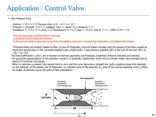
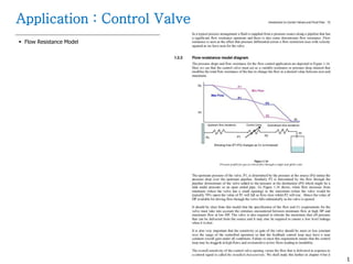
Why PressureDrop
. Velocity 가 빨라짐으로 Pressure drop 발생 – 베르누이 정리
. Pressure 는 strength 개념이고 (voltage), Flow 는 speed 개념 (Ampere) 이다
. Resistance 에 의하여 한번 Drop 되면 downstream 에 위치한 pipe 가 동일한 area 를 지녀도 100% 회복은 안됨
. Total pressure loss is derived from 2 sources:
1) frictional losses along the entrance
2) throat and inertial losses stemming from the sudden expansion, causing flow separation and eddies (exit losses).
Frictional losses are linearly related to flow, Q (law of Poiseuille), and exit losses increase with the square of the flow caused by
convective acceleration in the narrowed segment (law of Bernoulli). Total pressure gradient (ΔP) is the sum of the two: ΔP= (f1
×Q) + (f2×Q2).
The loss coefficients f1 and f2 are a function of stenosis geometry and rheologic properties of blood (viscosity and density).
The graphical representation of this equation results in a quadratic relationship, where the curvilinear shape demonstrates the pr
esence of nonlinear exit losses.
When no stenosis is present, the second term is zero and the curve becomes a straight line (with a positive slope that depends
on the diameter of the vessel; law of Poiseuille). As indicates area of the stenosis; An, area of the normal segment; and Ls, effect
ive length of stenosis (up to the point of flow separation).
Application : Control Valve
44
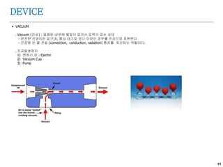
VACUUM
. Vacuum(진공) : 밀폐된 내부에 물질이 없어서 압력이 없는 상태
- 완전한 진공이란 없으며, 통상 대기압 보다 이하인 경우를 진공으로 표현한다
- 진공병 은 열 전달 (convection, conduction, radiation) 통로를 차단하는 역할이다.
. 진공발생장치
1) 벤츄리 관 : Ejector
2) Vacuum Cup
3) Pump
DEVICE
46.
45
DEVICE
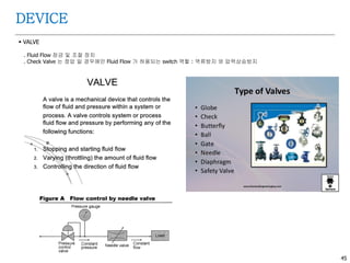
VALVE
. FluidFlow 잠금 및 조절 장치
. Check Valve 는 정압 일 경우에만 Fluid Flow 가 허용되는 switch 역할 : 역류방지 와 압력상승방지
47.
46
DEVICE
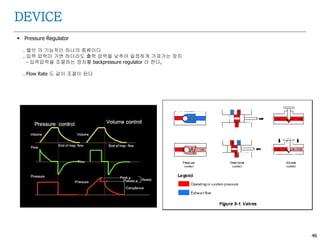
Pressure Regulator
.밸브 의 기능적인 하나의 종류이다
. 입력 압력이 가변 하더라도 출력 압력을 낮추어 일정하게 가져가는 장치
- 입력압력을 조절하는 장치를 backpressure regulator 라 한다,
. Flow Rate 도 같이 조절이 된다
48.
47
DEVICE
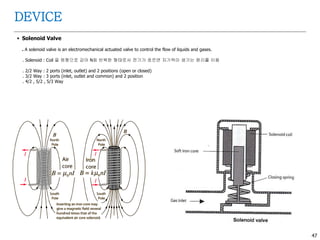
Solenoid Valve
.A solenoid valve is an electromechanical actuated valve to control the flow of liquids and gases.
. Solenoid : Coil 을 원형으로 감아 N회 반복한 형태로서 전기가 흐르면 자기력이 생기는 원리를 이용
. 2/2 Way : 2 ports (inlet, outlet) and 2 positions (open or closed)
. 3/2 Way : 3 ports (inlet, outlet and common) and 2 position
. 4/2 , 5/2 , 5/3 Way
49.
48
DEVICE
Flow Meter
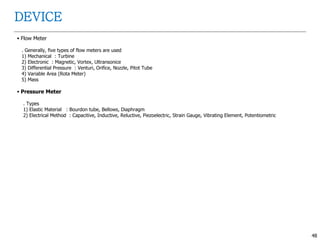
.Generally, five types of flow meters are used
1) Mechanical : Turbine
2) Electronic : Magnetic, Vortex, Ultransonice
3) Differential Pressure : Venturi, Orifice, Nozzle, Pitot Tube
4) Variable Area (Rota Meter)
5) Mass
Pressure Meter
. Types
1) Elastic Material : Bourdon tube, Bellows, Diaphragm
2) Electrical Method : Capacitive, Inductive, Reluctive, Piezoelectric, Strain Gauge, Vibrating Element, Potentiometric
50
DEVICE
PUMP
. Pump란 Sample 가스를 흡입하여 배출하는 기능을 갖는다
. Pump 란 진공과 고압을 만드는 장치이다
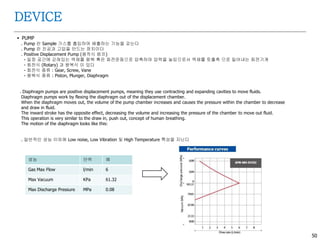
. Positive Displacement Pump (용적식 펌프)
- 일정 공간에 갇혀있는 액체를 왕복 혹은 회전운동으로 압축하여 압력을 높임으로서 액체를 토출측 으로 밀어내는 회전기계
- 회전식 (Rotary) 과 왕복식 이 있다
- 회전식 종류 : Gear, Screw, Vane
- 왕복식 종류 : Piston, Plunger, Diaphragm
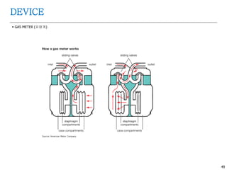
. Diaphragm pumps are positive displacement pumps, meaning they use contracting and expanding cavities to move fluids.
Diaphragm pumps work by flexing the diaphragm out of the displacement chamber.
When the diaphragm moves out, the volume of the pump chamber increases and causes the pressure within the chamber to decrease
and draw in fluid.
The inward stroke has the opposite effect, decreasing the volume and increasing the pressure of the chamber to move out fluid.
This operation is very similar to the draw in, push out, concept of human breathing.
The motion of the diaphragm looks like this:
. 일반적인 성능 이외에 Low noise, Low Vibration 및 High Temperature 특성을 지닌다
성능 단위 예
Gas Max Flow l/min 6
Max Vacuum KPa 61.32
Max Discharge Pressure MPa 0.08
52
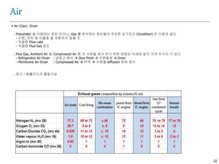
Air
Air (Gas)Dryer
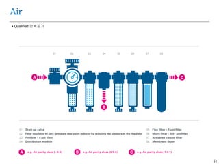
. Pneumatic 을 이용하는 장치 이거나, Gas 를 분석하는 장비들의 주요한 요구조건 (Condition) 은 다음과 같다
- 수분, 먼지 및 이물질 을 포함하지 않을 것
- 적절한 Flow rate
- 적절한 Flue Gas 온도
. Flue Gas, Ambient Air 및 Compressed Air 중 의 수분을 제거 하기 위한 방법은 아래와 같이 크게 두가지 가 있다
- Refrigerator Air Dryer : 냉장고 원리 Dew Point 수분발생 Drain
- Membrane Air Dryer : Compressed Air 박막 수분을 diffusion 하여 제거
. 참고 : 배출가스의 물질구성
54.
53
Air
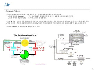
Refrigerator AirDryer
. 물질의 상태변화 시 주변 에너지를 흡수 하거나 발생에너지를 방출하는 원리를 이용
-. 액체 기체 (Vaporize) : 주변 에너지 (열) 을 필요로 한다 주변 열을 흡수하여 차갑게 만든다
-. 기체 액체 (Condensate) : 내부 에너지(열) 을 방출한다
. 기체 액체 : 기체가 고온 상태이면 주변온도에 의하여 액체로 변하고, 고압 상태이면 쉽게 액화할 수 있는 조건을 만들어 준다.
. 액체 기체 : 주변의 잠열에 의하여 기화 되며, 액체가 저압 상태이면 주변온도에 의하여 쉽게 기화할 수 있는 조건이 된다
. 물질은 Freon 을 사용하며 이를 촉매(냉매) 라 한다
Vapor
High PressureVapor
LiquidLiquid + Vapor
Low Pressure
55.
54
Air
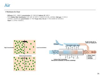
Membrane AirDryer
. Diffusion 원리 : 물질의 concentration 은 이동하여 balance 를 맞춘다
. 박막 (hollow fiber membrane) 으로 내부 와 외부가 구성되어 있으며, 내부에는 Wet gas 가 흐르고
외부에는 상대적으로 concentration 이 작은 Purge (Inst. Air) air 가 반대 방향으로 흐르면서
Vapor 는 외부로 이동한다.
56.
55
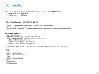
Connector
장치와 연결부위및 호스 와 연결부위를 지님으로 두 가지 규격을 reference 한다
1) Hose (Pipe) 부분 : NPS or DN
2) Thread 부분 : NPT or G
Pipe Thread Standard : 장치에 연결되는 돌출부분
1) NPT : National Pipe Thread (America) or BSP (British Standard Pipe)
2) M thread : Standard in Europe
3) R or G thread (Whitworth) : Cylindrical threads which are mainly used in countries with imperial system
배관 (tube, pipe) 규격
1) IPS (Iron Pipe Size)
2) NPS (Nominal Pipe Size) : 외경(OD) 기준, Inch 사용
3) DN (Diameter Nominal) : NPS 규격 Inch 를 미터법으로 표기
. NPS ¼” : DN 10, NPS 1/8” : DN 6
. DN 4/6 의 외경은 6mm, 내경은 4mm 이다
. DN 6/8 의 외경은 8mm, 내경은 6mm 이다
* Connector 의 PTFE 는 외경, 내경을 따지지만 (내경 부분에 capillary 관이 있다) , SS 는 외경만 따진다
재질
1) PP : Polypropylene
2) PVDF : Polyvinylidene Fluoride
3) PTFE
4) PFA : Polyfluoroakoxy
5) Viton
6) Novoprene
7) Stainless Steel
57.
56
Connector
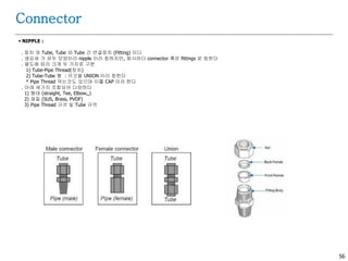
NIPPLE :
.장치 와 Tube, Tube 와 Tube 간 연결장치 (Fitting) 이다
. 생김새 가 유두 모양이라 nipple 이라 칭하지만, 회사마다 connector 혹은 fittings 로 칭한다
. 용도에 따라 크게 두 가지로 구분
1) Tube-Pipe Thread(장치)
2) Tube-Tube 형 : 이것을 UNION 이라 칭한다
* Pipe Thread 막는것도 있으며 이를 CAP 이라 한다
. 아래 세가지 조합되어 다양하다
1) 형태 (straight, Tee, Elbow,,)
2) 재질 (SUS, Brass, PVDF)
3) Pipe Thread 규격 및 Tube 규격