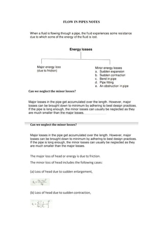
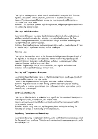
FLOW IN PIPES NOTES
Minor losses in pipe flow refer to the energy losses that occur due to various factors
other than the frictional resistance along the length of the pipe. These losses are often
associated with specific components or features in a piping system. Some of the main
factors contributing to minor losses in pipe flow include:
Sudden Expansion or Contraction: When a pipe abruptly changes its diameter (either
expands or contracts), it leads to a loss of energy. This is due to the disruption in the
flow pattern.
Bends and Elbows: Sharp bends, elbows, and other changes in direction cause
additional energy losses. The flow separation at these points leads to increased
turbulence.
Valves and Fittings: Any kind of obstruction in the flow path, such as valves, tees,
and other fittings, results in minor energy losses.
Entrance and Exit Effects: Flow patterns are not uniform near the entrance and exit of
a pipe. This non-uniformity leads to additional losses.
Sudden Enlargement: Similar to sudden expansions, abrupt enlargements in the pipe
diameter can lead to energy losses.
Sudden Contraction: Sudden contractions in pipe diameter can lead to increased
turbulence and energy losses.
Pipe Entrances: The way a pipe connects to a tank or reservoir can cause flow
disturbances and energy losses.
Screens and Filters: These can cause additional resistance to flow, leading to minor
losses.
Throttling Devices: Devices like orifices and nozzles that are used to control flow can
introduce additional energy losses.
Pipe Material and Roughness: The material of the pipe and the roughness of its inner
surface can also contribute to minor losses.
Local Disturbances: Any irregularities or disturbances in the flow path can lead to
additional losses.
It's important to note that these losses are termed "minor" because they are usually
smaller in magnitude compared to the major loss, which is due to friction along the
length of the pipe. However, in certain situations, especially in systems with a large
number of fittings or components, the cumulative effect of these minor losses can be
significant and should be considered in system design and analysis. Engineers often
use empirical equations and coefficients to estimate these losses in practical
applications.
Major Lose in Pipe flow
Major losses in pipes, also known as frictional losses, occur due to the resistance
encountered by the fluid as it flows through the pipe. This resistance is primarily
caused by the interaction between the fluid and the inner surface of the pipe. The main
factors contributing to major losses include:
Pipe Length:
Description: The longer the pipe, the greater the frictional losses. This is because the
fluid has to overcome more surface area, resulting in higher resistance.
Solution: To mitigate this, engineers may use larger diameter pipes or select materials
with lower friction coefficients.
Flow Velocity:
Description: Higher flow velocities lead to greater frictional losses. This is because
faster-moving fluid interacts more vigorously with the pipe walls.
Solution: Controlling flow velocity through proper pipe sizing and system design can
help manage major losses.
Pipe Roughness:
Description: The roughness of the inner surface of the pipe affects friction. Rougher
surfaces create more resistance compared to smoother surfaces.
Solution: Using pipes with smoother inner linings and regular maintenance to prevent
scaling or buildup can help reduce friction.
Viscosity of the Fluid:
Description: Highly viscous fluids, like heavy oils, experience higher frictional losses
compared to less viscous fluids like water.
Solution: In cases where highly viscous fluids are used, consideration must be given
to pipe diameter and material selection.
Pipe Diameter:
Description: Smaller diameter pipes result in higher flow velocities for a given flow
rate, leading to increased frictional losses.
Solution: Selecting appropriately sized pipes based on flow requirements can help
minimize major losses.
Type of Pipe Material:
Description: Different materials have varying levels of surface roughness and friction
characteristics. For example, smooth materials like PVC create less friction compared
to rougher materials like cast iron.
Solution: Choosing materials with low friction coefficients can reduce major losses.
Bends, Fittings, and Valves:
Description: Any change in direction or shape of the pipe, such as bends, fittings, and
valves, introduces additional resistance.
Solution: Careful design and selection of components can help minimize the impact of
these elements on major losses.
Temperature and Density Changes:
Description: Changes in fluid temperature and density can affect viscosity and flow
behavior, influencing major losses.
Solution: Proper insulation, flow control devices, and consideration of temperature
effects are important in managing major losses.
PIPELINE PROLEMS
All pipeline problems should be solved by applying Bernoulli’s theorem between
points for which the total energy is known and including expressions for any loss of
energy due to shock or to friction, thus
In pipeline systems, there are several practical problems that can arise, ranging from
mechanical issues to operational and environmental concerns. Here are some common
practical pipeline problems:
Corrosion:
Description: Corrosion is the gradual degradation of pipeline materials due to
chemical reactions with the environment. It can weaken the pipeline structure and
lead to leaks or ruptures.
Causes: Exposure to corrosive substances in the transported fluid, soil conditions, and
atmospheric factors can contribute to corrosion.
Solution: Regular inspection, protective coatings, and cathodic protection systems are
used to mitigate corrosion.
Leakage:
Description: Leakage occurs when there is an unintended escape of fluid from the
pipeline. This can be a result of cracks, corrosion, or mechanical damage.
Causes: Corrosion, material fatigue, ground movement, or external forces (e.g.,
excavation) can cause leaks.
Solution: Leak detection systems, regular inspections, and prompt repairs are essential
for addressing leakage issues.
Blockages and Obstructions:
Description: Blockages can occur due to the accumulation of debris, sediment, or
solid deposits inside the pipeline, reducing or completely obstructing the flow.
Causes: Improper maintenance, accumulation of foreign materials, and changes in
fluid properties can lead to blockages.
Solution: Routine cleaning and maintenance activities, such as pigging (using devices
to clean or inspect pipelines), are used to clear blockages.
Pressure Loss:
Description: Pressure loss refers to the decrease in fluid pressure along the length of
the pipeline. It can affect the efficiency and effectiveness of the pipeline system.
Causes: Friction with the pipe walls, fittings, and other components, as well as
elevation changes, can lead to pressure loss.
Solution: Proper design, use of smooth materials, and regular maintenance to
minimize friction can help manage pressure loss.
Freezing and Temperature Extremes:
Description: In cold climates, water or other fluids in pipelines can freeze, potentially
leading to blockages or even pipe bursts.
Causes: Low temperatures and inadequate insulation can lead to freezing.
Solution: Proper insulation and heat tracing systems are used to prevent freezing.
Additionally, in extreme temperatures, heat exchangers or other temperature control
methods may be employed.
Environmental Impact:
Description: Pipeline spills or leaks can have significant environmental consequences,
affecting ecosystems, water bodies, and human health.
Causes: Accidents, equipment failures, or inadequate safety measures can lead to
environmental impacts.
Solution: Robust safety protocols, spill response plans, and regular training for
personnel are critical to minimizing environmental risks.
Regulatory Compliance and Permitting:
Description: Ensuring compliance with local, state, and federal regulations is essential
for the operation of pipelines. Obtaining and maintaining the necessary permits can be
a complex process.
Causes: Changing regulations, environmental concerns, and community opposition
can lead to compliance challenges.
Solution: Engaging with regulatory authorities, conducting environmental impact
assessments, and implementing best practices for compliance are crucial.
Addressing these practical pipeline problems requires a combination of proactive
maintenance, effective monitoring, and adherence to industry best practices and
regulatory requirements. Additionally, continuous advancements in technology and
materials play a significant role in mitigating these challenges.
DISCHARGE TO ATMOSPHERE
In the context of pipelines and fluid flow, "discharge to atmosphere" refers to the
intentional release of fluid (liquid or gas) from a confined system or pipeline into the
surrounding open air or atmosphere. This can occur for various reasons, such as
relieving excess pressure, expelling unwanted materials, or venting gases.
Practical Examples and Applications:
Pressure Relief Valve (PRV) Operation:
Description: In pipelines handling pressurized fluids, pressure relief valves are
installed as safety devices. When the pressure exceeds a certain setpoint, the valve
opens, allowing excess fluid to discharge to the atmosphere.
Example: In a chemical processing plant, a PRV on a reactor vessel may open to
relieve pressure in case of an overpressure condition, preventing potential damage to
the vessel.
Purge and Vent Operations:
Description: In some pipeline systems, especially those transporting hazardous or
volatile materials, purging and venting operations are conducted to remove air, gas, or
unwanted substances before or after a process.
Example: In natural gas pipelines, purging is performed before commissioning a new
section of the pipeline to ensure that any air or non-condensable gases are removed.
Blowdown Systems:
Description: Blowdown systems are used to depressurize a section of the pipeline by
releasing fluid to the atmosphere. This is done to allow maintenance or to isolate a
section of the pipeline.
Example: In a steam boiler system, a blowdown valve can be opened periodically to
remove impurities and prevent the buildup of scale.
Emergency Venting in Storage Tanks:
Description: Storage tanks, especially those containing volatile or hazardous materials,
are equipped with emergency venting systems to release excess pressure in case of
over-pressurization.
Example: In a chemical storage tank, if the pressure exceeds safe levels due to
temperature changes or other factors, the emergency vent opens to discharge gas or
vapor safely.
Venting During Pipeline Pigging:
Description: Pipeline pigging involves sending a device (a "pig") through the pipeline
for cleaning, inspection, or other purposes. Venting may be necessary during this
process.
Example: In a natural gas pipeline, before sending a cleaning pig through, operators
might vent the line to ensure safety and allow the pig to move smoothly.
Pipeline Draining and Decommissioning:
Description: When a pipeline needs to be taken out of service, it may be drained and
decommissioned. This often involves venting the residual fluid or gas.
Example: A pipeline that is no longer in use may be emptied and vented before it is
taken out of service or repurposed.
It's important to note that while discharge to atmosphere is sometimes necessary for
safety or operational reasons, it should be done in compliance with environmental
regulations and best practices to minimize any potential impact on the environment.
Additionally, measures should be taken to ensure that any discharged substances are
not harmful or pose a risk to human health or the ecosystem.
WHY DISCHARGE TO ATMOSPHERE IS A PROBLEM AND HOW TO
MITIGATE IT
Discharge to atmosphere from a pipeline can be a problem depending on the context
and the nature of the fluid being discharged. Here are a few considerations:
Environmental Impact:
Discharging certain fluids, especially hazardous or polluting substances, directly into
the atmosphere can have significant environmental consequences. It may lead to air
pollution, contamination of soil and water, and harm to local ecosystems.
Regulatory Compliance:
Many jurisdictions have strict regulations governing the discharge of fluids into the
atmosphere. These regulations often dictate permissible substances, quantities, and
conditions for discharge. Violating these regulations can lead to fines and legal
consequences.
Safety Concerns:
Discharging certain gases or volatile substances can pose safety risks, especially if
they are flammable, toxic, or pose other health hazards. Proper venting and control
measures are necessary to ensure safety.
Loss of Valuable Resources:
In some cases, the fluid being discharged may be valuable or useful, and allowing it to
escape into the atmosphere represents a loss of resources.
Waste Management:
Discharging fluids into the atmosphere can be considered a form of waste. Managing
and treating these wastes may be necessary to meet environmental standards.
Public Perception:
Depending on the location and the substance being discharged, there may be public
concerns or objections to the practice.
To mitigate these potential problems, engineers and operators implement various
measures, including:
Treatment and Filtration: Install systems to treat and filter fluids before discharge to
remove pollutants or contaminants.
Recapture and Recycling: Implement processes to capture and recycle valuable
substances from the discharged fluid.
Emission Control Devices: Use specialized equipment like scrubbers, filters, and
incinerators to reduce emissions and pollutants before discharge.
Compliance with Regulations: Ensure that all discharge activities comply with local,
state, and federal regulations.
Safety Protocols: Implement safety measures to prevent accidents or hazards
associated with discharging specific types of fluids.
Monitoring and Reporting: Regularly monitor discharge activities and report relevant
data to regulatory authorities to demonstrate compliance.
Ultimately, whether discharge to atmosphere is a problem depends on the specific
circumstances, the nature of the fluid, and the applicable regulatory framework. It's
essential to approach this issue with careful consideration of environmental, safety,
and legal implications.
HYDRAULIC GRADIENT IN PIPE FLOW
The hydraulic gradient in pipe flow is a concept used to describe the energy
distribution along a pipeline. It represents the change in total energy per unit length of
the pipe. The total energy is the sum of the pressure energy, velocity energy, and
elevation energy of the fluid.
Mathematically, the hydraulic gradient (�I) is defined as:
Let's explore this concept with a practical example:
Practical Example: Water Distribution System
Consider a water distribution system where water is pumped from a reservoir and
transported through a network of pipes to reach households. The system has various
components including pumps, pipes, valves, and fittings.
Pumping Station (Start Point):
At the pumping station, water is pressurized to a certain level. This increases the
pressure energy (Δ�ΔP).
Pipeline Flow:
As water flows through the pipeline, it experiences frictional losses (major losses) due
to the interaction with the pipe walls. This leads to a decrease in pressure energy.
Elevation Changes:
The pipeline may encounter changes in elevation. For example, it may go uphill or
downhill. These changes in elevation affect the elevation energy (�z).
Velocity Changes:
If the flow rate changes along the pipeline, it will influence the velocity energy term
(�2/2�V2/2g).
Interpretation:
At any given point in the system, the hydraulic gradient represents the combined
effect of pressure, velocity, and elevation changes. It quantifies how the total energy
changes as the fluid moves through the system.
Engineers use the hydraulic gradient to ensure that the system can maintain adequate
pressure and flow rates for its intended purpose. This is crucial for designing efficient
and reliable water supply systems.
By analyzing the hydraulic gradient, engineers can identify areas where additional
pumps, valves, or pipe modifications may be needed to optimize the system's
performance.
Overall, understanding the hydraulic gradient is fundamental in the design, operation,
and maintenance of water distribution systems, as well as other fluid transport
systems like oil pipelines or industrial fluid networks.

FLOW IN PIPES NOTES.pdf

  • 1.
  • 2.
    Minor losses inpipe flow refer to the energy losses that occur due to various factors other than the frictional resistance along the length of the pipe. These losses are often associated with specific components or features in a piping system. Some of the main factors contributing to minor losses in pipe flow include: Sudden Expansion or Contraction: When a pipe abruptly changes its diameter (either expands or contracts), it leads to a loss of energy. This is due to the disruption in the flow pattern. Bends and Elbows: Sharp bends, elbows, and other changes in direction cause additional energy losses. The flow separation at these points leads to increased turbulence. Valves and Fittings: Any kind of obstruction in the flow path, such as valves, tees, and other fittings, results in minor energy losses. Entrance and Exit Effects: Flow patterns are not uniform near the entrance and exit of a pipe. This non-uniformity leads to additional losses. Sudden Enlargement: Similar to sudden expansions, abrupt enlargements in the pipe diameter can lead to energy losses. Sudden Contraction: Sudden contractions in pipe diameter can lead to increased turbulence and energy losses. Pipe Entrances: The way a pipe connects to a tank or reservoir can cause flow disturbances and energy losses. Screens and Filters: These can cause additional resistance to flow, leading to minor losses. Throttling Devices: Devices like orifices and nozzles that are used to control flow can introduce additional energy losses. Pipe Material and Roughness: The material of the pipe and the roughness of its inner surface can also contribute to minor losses. Local Disturbances: Any irregularities or disturbances in the flow path can lead to additional losses.
  • 3.
    It's important tonote that these losses are termed "minor" because they are usually smaller in magnitude compared to the major loss, which is due to friction along the length of the pipe. However, in certain situations, especially in systems with a large number of fittings or components, the cumulative effect of these minor losses can be significant and should be considered in system design and analysis. Engineers often use empirical equations and coefficients to estimate these losses in practical applications. Major Lose in Pipe flow Major losses in pipes, also known as frictional losses, occur due to the resistance encountered by the fluid as it flows through the pipe. This resistance is primarily caused by the interaction between the fluid and the inner surface of the pipe. The main factors contributing to major losses include: Pipe Length: Description: The longer the pipe, the greater the frictional losses. This is because the fluid has to overcome more surface area, resulting in higher resistance. Solution: To mitigate this, engineers may use larger diameter pipes or select materials with lower friction coefficients. Flow Velocity: Description: Higher flow velocities lead to greater frictional losses. This is because faster-moving fluid interacts more vigorously with the pipe walls. Solution: Controlling flow velocity through proper pipe sizing and system design can help manage major losses. Pipe Roughness: Description: The roughness of the inner surface of the pipe affects friction. Rougher surfaces create more resistance compared to smoother surfaces. Solution: Using pipes with smoother inner linings and regular maintenance to prevent scaling or buildup can help reduce friction. Viscosity of the Fluid: Description: Highly viscous fluids, like heavy oils, experience higher frictional losses compared to less viscous fluids like water. Solution: In cases where highly viscous fluids are used, consideration must be given to pipe diameter and material selection. Pipe Diameter: Description: Smaller diameter pipes result in higher flow velocities for a given flow rate, leading to increased frictional losses. Solution: Selecting appropriately sized pipes based on flow requirements can help minimize major losses.
  • 4.
    Type of PipeMaterial: Description: Different materials have varying levels of surface roughness and friction characteristics. For example, smooth materials like PVC create less friction compared to rougher materials like cast iron. Solution: Choosing materials with low friction coefficients can reduce major losses. Bends, Fittings, and Valves: Description: Any change in direction or shape of the pipe, such as bends, fittings, and valves, introduces additional resistance. Solution: Careful design and selection of components can help minimize the impact of these elements on major losses. Temperature and Density Changes: Description: Changes in fluid temperature and density can affect viscosity and flow behavior, influencing major losses. Solution: Proper insulation, flow control devices, and consideration of temperature effects are important in managing major losses. PIPELINE PROLEMS All pipeline problems should be solved by applying Bernoulli’s theorem between points for which the total energy is known and including expressions for any loss of energy due to shock or to friction, thus In pipeline systems, there are several practical problems that can arise, ranging from mechanical issues to operational and environmental concerns. Here are some common practical pipeline problems: Corrosion: Description: Corrosion is the gradual degradation of pipeline materials due to chemical reactions with the environment. It can weaken the pipeline structure and lead to leaks or ruptures. Causes: Exposure to corrosive substances in the transported fluid, soil conditions, and atmospheric factors can contribute to corrosion. Solution: Regular inspection, protective coatings, and cathodic protection systems are used to mitigate corrosion. Leakage:
  • 5.
    Description: Leakage occurswhen there is an unintended escape of fluid from the pipeline. This can be a result of cracks, corrosion, or mechanical damage. Causes: Corrosion, material fatigue, ground movement, or external forces (e.g., excavation) can cause leaks. Solution: Leak detection systems, regular inspections, and prompt repairs are essential for addressing leakage issues. Blockages and Obstructions: Description: Blockages can occur due to the accumulation of debris, sediment, or solid deposits inside the pipeline, reducing or completely obstructing the flow. Causes: Improper maintenance, accumulation of foreign materials, and changes in fluid properties can lead to blockages. Solution: Routine cleaning and maintenance activities, such as pigging (using devices to clean or inspect pipelines), are used to clear blockages. Pressure Loss: Description: Pressure loss refers to the decrease in fluid pressure along the length of the pipeline. It can affect the efficiency and effectiveness of the pipeline system. Causes: Friction with the pipe walls, fittings, and other components, as well as elevation changes, can lead to pressure loss. Solution: Proper design, use of smooth materials, and regular maintenance to minimize friction can help manage pressure loss. Freezing and Temperature Extremes: Description: In cold climates, water or other fluids in pipelines can freeze, potentially leading to blockages or even pipe bursts. Causes: Low temperatures and inadequate insulation can lead to freezing. Solution: Proper insulation and heat tracing systems are used to prevent freezing. Additionally, in extreme temperatures, heat exchangers or other temperature control methods may be employed. Environmental Impact: Description: Pipeline spills or leaks can have significant environmental consequences, affecting ecosystems, water bodies, and human health. Causes: Accidents, equipment failures, or inadequate safety measures can lead to environmental impacts. Solution: Robust safety protocols, spill response plans, and regular training for personnel are critical to minimizing environmental risks. Regulatory Compliance and Permitting: Description: Ensuring compliance with local, state, and federal regulations is essential for the operation of pipelines. Obtaining and maintaining the necessary permits can be a complex process.
  • 6.
    Causes: Changing regulations,environmental concerns, and community opposition can lead to compliance challenges. Solution: Engaging with regulatory authorities, conducting environmental impact assessments, and implementing best practices for compliance are crucial. Addressing these practical pipeline problems requires a combination of proactive maintenance, effective monitoring, and adherence to industry best practices and regulatory requirements. Additionally, continuous advancements in technology and materials play a significant role in mitigating these challenges. DISCHARGE TO ATMOSPHERE In the context of pipelines and fluid flow, "discharge to atmosphere" refers to the intentional release of fluid (liquid or gas) from a confined system or pipeline into the surrounding open air or atmosphere. This can occur for various reasons, such as relieving excess pressure, expelling unwanted materials, or venting gases. Practical Examples and Applications: Pressure Relief Valve (PRV) Operation: Description: In pipelines handling pressurized fluids, pressure relief valves are installed as safety devices. When the pressure exceeds a certain setpoint, the valve opens, allowing excess fluid to discharge to the atmosphere. Example: In a chemical processing plant, a PRV on a reactor vessel may open to relieve pressure in case of an overpressure condition, preventing potential damage to the vessel. Purge and Vent Operations: Description: In some pipeline systems, especially those transporting hazardous or volatile materials, purging and venting operations are conducted to remove air, gas, or unwanted substances before or after a process. Example: In natural gas pipelines, purging is performed before commissioning a new section of the pipeline to ensure that any air or non-condensable gases are removed. Blowdown Systems: Description: Blowdown systems are used to depressurize a section of the pipeline by releasing fluid to the atmosphere. This is done to allow maintenance or to isolate a section of the pipeline. Example: In a steam boiler system, a blowdown valve can be opened periodically to remove impurities and prevent the buildup of scale. Emergency Venting in Storage Tanks: Description: Storage tanks, especially those containing volatile or hazardous materials, are equipped with emergency venting systems to release excess pressure in case of over-pressurization.
  • 7.
    Example: In achemical storage tank, if the pressure exceeds safe levels due to temperature changes or other factors, the emergency vent opens to discharge gas or vapor safely. Venting During Pipeline Pigging: Description: Pipeline pigging involves sending a device (a "pig") through the pipeline for cleaning, inspection, or other purposes. Venting may be necessary during this process. Example: In a natural gas pipeline, before sending a cleaning pig through, operators might vent the line to ensure safety and allow the pig to move smoothly. Pipeline Draining and Decommissioning: Description: When a pipeline needs to be taken out of service, it may be drained and decommissioned. This often involves venting the residual fluid or gas. Example: A pipeline that is no longer in use may be emptied and vented before it is taken out of service or repurposed. It's important to note that while discharge to atmosphere is sometimes necessary for safety or operational reasons, it should be done in compliance with environmental regulations and best practices to minimize any potential impact on the environment. Additionally, measures should be taken to ensure that any discharged substances are not harmful or pose a risk to human health or the ecosystem. WHY DISCHARGE TO ATMOSPHERE IS A PROBLEM AND HOW TO MITIGATE IT Discharge to atmosphere from a pipeline can be a problem depending on the context and the nature of the fluid being discharged. Here are a few considerations: Environmental Impact: Discharging certain fluids, especially hazardous or polluting substances, directly into the atmosphere can have significant environmental consequences. It may lead to air pollution, contamination of soil and water, and harm to local ecosystems. Regulatory Compliance: Many jurisdictions have strict regulations governing the discharge of fluids into the atmosphere. These regulations often dictate permissible substances, quantities, and conditions for discharge. Violating these regulations can lead to fines and legal consequences. Safety Concerns: Discharging certain gases or volatile substances can pose safety risks, especially if they are flammable, toxic, or pose other health hazards. Proper venting and control measures are necessary to ensure safety.
  • 8.
    Loss of ValuableResources: In some cases, the fluid being discharged may be valuable or useful, and allowing it to escape into the atmosphere represents a loss of resources. Waste Management: Discharging fluids into the atmosphere can be considered a form of waste. Managing and treating these wastes may be necessary to meet environmental standards. Public Perception: Depending on the location and the substance being discharged, there may be public concerns or objections to the practice. To mitigate these potential problems, engineers and operators implement various measures, including: Treatment and Filtration: Install systems to treat and filter fluids before discharge to remove pollutants or contaminants. Recapture and Recycling: Implement processes to capture and recycle valuable substances from the discharged fluid. Emission Control Devices: Use specialized equipment like scrubbers, filters, and incinerators to reduce emissions and pollutants before discharge. Compliance with Regulations: Ensure that all discharge activities comply with local, state, and federal regulations. Safety Protocols: Implement safety measures to prevent accidents or hazards associated with discharging specific types of fluids. Monitoring and Reporting: Regularly monitor discharge activities and report relevant data to regulatory authorities to demonstrate compliance. Ultimately, whether discharge to atmosphere is a problem depends on the specific circumstances, the nature of the fluid, and the applicable regulatory framework. It's essential to approach this issue with careful consideration of environmental, safety, and legal implications. HYDRAULIC GRADIENT IN PIPE FLOW
  • 9.
    The hydraulic gradientin pipe flow is a concept used to describe the energy distribution along a pipeline. It represents the change in total energy per unit length of the pipe. The total energy is the sum of the pressure energy, velocity energy, and elevation energy of the fluid. Mathematically, the hydraulic gradient (�I) is defined as: Let's explore this concept with a practical example: Practical Example: Water Distribution System Consider a water distribution system where water is pumped from a reservoir and transported through a network of pipes to reach households. The system has various components including pumps, pipes, valves, and fittings. Pumping Station (Start Point): At the pumping station, water is pressurized to a certain level. This increases the pressure energy (Δ�ΔP). Pipeline Flow: As water flows through the pipeline, it experiences frictional losses (major losses) due to the interaction with the pipe walls. This leads to a decrease in pressure energy. Elevation Changes: The pipeline may encounter changes in elevation. For example, it may go uphill or downhill. These changes in elevation affect the elevation energy (�z). Velocity Changes: If the flow rate changes along the pipeline, it will influence the velocity energy term (�2/2�V2/2g). Interpretation:
  • 10.
    At any givenpoint in the system, the hydraulic gradient represents the combined effect of pressure, velocity, and elevation changes. It quantifies how the total energy changes as the fluid moves through the system. Engineers use the hydraulic gradient to ensure that the system can maintain adequate pressure and flow rates for its intended purpose. This is crucial for designing efficient and reliable water supply systems. By analyzing the hydraulic gradient, engineers can identify areas where additional pumps, valves, or pipe modifications may be needed to optimize the system's performance. Overall, understanding the hydraulic gradient is fundamental in the design, operation, and maintenance of water distribution systems, as well as other fluid transport systems like oil pipelines or industrial fluid networks.