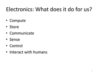
Flavors of Electronics
An exploration of a few simple ideas
1
P Joy Prabhakaran
https://www.linkedin.com/profile/view?id=22548506&trk=hp-identity-name
Electronics: What does it do for us?
• Compute
• Store
• Communicate
• Sense
• Control
• Interact with humans
2
Binary numbers
Decimal numbers
– Base 10
– 10 symbols: 0 to 9
– 576 = 5 x 10² + 7 x 101 + 6 x 100
Binary numbers
– Base 2
– 2 symbols: 0 & 1
– 101 = 1 x 22 + 0 x 21 + 1 x 20 = ? In decimal
3
Compute: How?
• Logic
NOT, OR, AND, XOR
• Numeric Comparison
=, >, <
• Arithmetic
ADD, SUB, MULT, DIV
Can all these be built using the switches shown here?
4
Many of the ideas here are probably derived from Shannon’s work referred to at:
http://en.wikipedia.org/wiki/A_Symbolic_Analysis_of_Relay_and_Switching_Circuits
The NOT gate
A few notations:
5V, 1, ON, TRUE are all used in a near synonymous manner.
The switch is “pressed” when the Input is 1.
If the connection to 5V is not present, the output is at 0.
Also referred to as OFF or FALSE at times.
With that out of the way let us explore what the NOT
logic is and if we can implement it using these
switches.
5
I/P O/P
1 0
0 1
AND
What should an “AND” implementation do?
How can this be built using our switches?
6
A B O/P
0 0 0
0 1 0
1 0 0
1 1 1
OR
What should an “OR” implementation do?
How can this be built using our switches?
7
A B O/P
0 0 0
0 1 1
1 0 1
1 1 1
XOR
What should an “XOR” implementation do?
How can this be built using our switches?
8
A B O/P
0 0 0
0 1 1
1 0 1
1 1 0
NAND
How about a NAND (following truth table)?
9
A B O/P
0 0 1
0 1 1
1 0 1
1 1 0
Gates and the symbols to denote them
10
Checking for equality
11
What does the following do?
O/P = 𝐴. 𝐵 + 𝐴. 𝐵
A B O/P
0 0 1
0 1 0
1 0 0
1 1 1
Build a circuit to check equality of two 2-bit numbers A1A0 and B1B0
O/P = (𝐴1. 𝐵1 + 𝐴1. 𝐵1) . (𝐴0. 𝐵0 + 𝐴0. 𝐵0)
What if we use an XNOR?
Comparing two numbers
A = B (𝐴1. 𝐵1 + 𝐴1. 𝐵1) . (𝐴0. 𝐵0 + 𝐴0. 𝐵0)
12
(𝐴1. 𝐵1) + (𝐴1. 𝐵1 + 𝐴1. 𝐵1) . (𝐴0. 𝐵0)A > B
Let us work out the truth table for A > B.
How would you implement A < B.
Logic to compare two 2 bit numbers
Addition: One bit half adder
A one bit half adder:
What is the truth table for S and Cout?
13
Two inputs (A, B) and two outputs (S, Cout)
Addition operation
A B S Cout
0 0 0 0
0 1 1 0
1 0 1 0
1 1 0 1
What is the logic for S and Cout?
𝑆 = 𝐴 ⊕ 𝐵
𝐶𝑜𝑢𝑡 = 𝐴 . 𝐵
One bit full adder
A one bit full adder:
What is the truth table for S and Cout?
14
Three inputs (A, B, C) and two outputs (S, Cout)
Addition operation
A B C S Cout
0 0 0 0 0
0 1 0 1 0
1 0 0 1 0
1 1 0 0 1
0 0 1 1 0
0 1 1 0 1
1 0 1 0 1
1 1 1 1 1
… and the logic S and Cout?
𝑆 = 𝐴. 𝐵. 𝐶 + 𝐴. 𝐵. 𝐶 + 𝐴. 𝐵. 𝐶 + 𝐴. 𝐵. 𝐶
𝐶𝑜𝑢𝑡 = 𝐴 . 𝐵 + 𝐴. 𝐶 + 𝐵. 𝐶
• S is true if only one input is true
or if all three are true.
• Cout is true if any two inputs are
true.
Build an 8 bit adder
15
Latches & Flip Flops
• Latches & Flip flops are built using basic gates and
can store data.
• They can be level triggered or edge triggered.
• They are an intrinsic part of storage, counters etc.
16
S R CLK D Q 𝐐
0 1 X X 1 0
1 0 X X 0 1
0 0 X X Unstable
1 1 ↑ 1 1 0
1 1 ↑ 0 0 1
1 1 ↓ X No change
1 1 ― X No change
The D flip flop
What would this circuit do
18
• R is made zero and then kept high throughout. After this, a clock is applied.
• What will the output be each time the clock goes high from low.
R Clk 𝑸 𝟑 𝑸 𝟐 𝑸 𝟏 𝑸 𝟎
0 X 0 0 0 0
1 ↑ 0 0 0 1
1 ↑ 0 0 1 1
1 ↑ 0 1 1 1
1 ↑ 1 1 1 1
… and what about this?
19
R Clk 𝑸 𝟑 𝑸 𝟐 𝑸 𝟏 𝑸 𝟎
0 X 0 0 0 0
1 ↑ 0 0 0 1
1 ↑ 0 0 1 1
1 ↑ 0 1 1 1
1 ↑ 1 1 1 1
1 ↑ 1 1 1 0
1 ↑ 1 1 0 0
1 ↑ 1 0 0 0
1 ↑ 0 0 0 0
Store: A few examples of data storage
• Mechanical
• Electrical
• Magnetic
• Optical
20
Store: A few examples of data storage
21
Magnetic storage
22
Source: http://en.wikipedia.org/wiki/Hard_disk_drive
Optical storage
23
http://www.britannica.com/EBchecked/media/106454/On-optical-discs-such-as-compact-
discs-and-digital-videodiscs?topicId=430490
A conceptual exploration of addressable and
programmable storage with no moving parts
24
What is O/P in relation with A1?
Assuming only one of A1 and A2 can be
1 at any time, what is the relationship
between A1 and A2 in the two
schematics on the right
Any ideas on how all this could lead to a memory device?
...conceptual exploration of memory
25
Discuss how the schematic can become the basic idea behind
devices like RAMs, EPROMs, EEPROMs etc with Ai becoming
the addressing mechanism
Communicate: How?
Send a signal from the source to the destination.
• Challenges
– How does one “send a signal”?
• Transmitter
• Conceptually, what should a transmitter look like?
– How does one receive a signal?
• Receiver
• Conceptually, what should a receiver look like?
– How does the signal go from the sender to the
receiver?
• Transmission channel and medium.
26
Sense: How?
• Sensors are used to sense. A sensor is a
transducer.
• A sensor (transducer) converts a physical
parameter into some other physical parameter
that can be used to sense the former. Example: A
thermometer
• In electronics and automated systems, the
physical parameter is typically converted to a
voltage or current for this can be easily
measured.
27
Physics behind a few common sensors
• Resistive sensors.
– Uses the fact that resistance of certain materials vary with
physical parameters. Eg: Resistive temperature detectors, Strain
gauges.
• Photoelectric sensors
– Uses the fact that a measurable current is generated in a
photo diode when exposed to light. Eg: Used in light sensors
• Thermocouples
– Uses the fact that Any junction of dissimilar metals will
produce an electric potential related to temperature. Eg:
Temp sensors used in Steel industry, water heaters etc.
• Piezo electric sensors
– Uses the fact that electric charge accumulates in certain
solid materials (such as crystals, certain biological matter
such as bone, DNA and some proteins) in response to
applied mechanical stress. Eg: Early use as a submarine sonar
by responding to the sonar echo. 28
A few basic concepts from analog
communication
• Wavelength
• Frequency
• Period
• Amplitude
• Low pass, high
pass, band
pass signals
29
Switching to the digital domain
• Sampling
• Quantization
• Quantization error
• Types of quantization
• Nyquist
30
Sampling
31
Quantization
32
Loss due to quantization.
33
Impact of quantization loss
34
Time domain – Frequency domain
35
Ideas in Information Theory and
compression
• Is all information created equal? Did you tell
me anything if you told me that the Sun rose
in the east today?
• What is ASCII code? Compare with a Variable
Length Code (VLC)?
• What if monochrome image is to be coded
with each pixel being a 0 or a 1 (like in Fax)?
Does any possibility to compress come to
mind?
36
…ideas in compression contd.
• Eliminating “unnecessary” and less important
information.
• Using the probability distribution of symbols
to arrive at a more efficient code.
• Regenerating parts of the data from other
parts of the data and a difference component.
• Dictionary coding.
37
The END
(only because I don’t know if anyone cares for this stuff)
38

A few fundamental concepts in digital electronics

  • 1.
    Flavors of Electronics Anexploration of a few simple ideas 1 P Joy Prabhakaran https://www.linkedin.com/profile/view?id=22548506&trk=hp-identity-name
  • 2.
    Electronics: What doesit do for us? • Compute • Store • Communicate • Sense • Control • Interact with humans 2
  • 3.
    Binary numbers Decimal numbers –Base 10 – 10 symbols: 0 to 9 – 576 = 5 x 10² + 7 x 101 + 6 x 100 Binary numbers – Base 2 – 2 symbols: 0 & 1 – 101 = 1 x 22 + 0 x 21 + 1 x 20 = ? In decimal 3
  • 4.
    Compute: How? • Logic NOT,OR, AND, XOR • Numeric Comparison =, >, < • Arithmetic ADD, SUB, MULT, DIV Can all these be built using the switches shown here? 4 Many of the ideas here are probably derived from Shannon’s work referred to at: http://en.wikipedia.org/wiki/A_Symbolic_Analysis_of_Relay_and_Switching_Circuits
  • 5.
    The NOT gate Afew notations: 5V, 1, ON, TRUE are all used in a near synonymous manner. The switch is “pressed” when the Input is 1. If the connection to 5V is not present, the output is at 0. Also referred to as OFF or FALSE at times. With that out of the way let us explore what the NOT logic is and if we can implement it using these switches. 5 I/P O/P 1 0 0 1
  • 6.
    AND What should an“AND” implementation do? How can this be built using our switches? 6 A B O/P 0 0 0 0 1 0 1 0 0 1 1 1
  • 7.
    OR What should an“OR” implementation do? How can this be built using our switches? 7 A B O/P 0 0 0 0 1 1 1 0 1 1 1 1
  • 8.
    XOR What should an“XOR” implementation do? How can this be built using our switches? 8 A B O/P 0 0 0 0 1 1 1 0 1 1 1 0
  • 9.
    NAND How about aNAND (following truth table)? 9 A B O/P 0 0 1 0 1 1 1 0 1 1 1 0
  • 10.
    Gates and thesymbols to denote them 10
  • 11.
    Checking for equality 11 Whatdoes the following do? O/P = 𝐴. 𝐵 + 𝐴. 𝐵 A B O/P 0 0 1 0 1 0 1 0 0 1 1 1 Build a circuit to check equality of two 2-bit numbers A1A0 and B1B0 O/P = (𝐴1. 𝐵1 + 𝐴1. 𝐵1) . (𝐴0. 𝐵0 + 𝐴0. 𝐵0) What if we use an XNOR?
  • 12.
    Comparing two numbers A= B (𝐴1. 𝐵1 + 𝐴1. 𝐵1) . (𝐴0. 𝐵0 + 𝐴0. 𝐵0) 12 (𝐴1. 𝐵1) + (𝐴1. 𝐵1 + 𝐴1. 𝐵1) . (𝐴0. 𝐵0)A > B Let us work out the truth table for A > B. How would you implement A < B. Logic to compare two 2 bit numbers
  • 13.
    Addition: One bithalf adder A one bit half adder: What is the truth table for S and Cout? 13 Two inputs (A, B) and two outputs (S, Cout) Addition operation A B S Cout 0 0 0 0 0 1 1 0 1 0 1 0 1 1 0 1 What is the logic for S and Cout? 𝑆 = 𝐴 ⊕ 𝐵 𝐶𝑜𝑢𝑡 = 𝐴 . 𝐵
  • 14.
    One bit fulladder A one bit full adder: What is the truth table for S and Cout? 14 Three inputs (A, B, C) and two outputs (S, Cout) Addition operation A B C S Cout 0 0 0 0 0 0 1 0 1 0 1 0 0 1 0 1 1 0 0 1 0 0 1 1 0 0 1 1 0 1 1 0 1 0 1 1 1 1 1 1 … and the logic S and Cout? 𝑆 = 𝐴. 𝐵. 𝐶 + 𝐴. 𝐵. 𝐶 + 𝐴. 𝐵. 𝐶 + 𝐴. 𝐵. 𝐶 𝐶𝑜𝑢𝑡 = 𝐴 . 𝐵 + 𝐴. 𝐶 + 𝐵. 𝐶 • S is true if only one input is true or if all three are true. • Cout is true if any two inputs are true.
  • 15.
    Build an 8bit adder 15
  • 16.
    Latches & FlipFlops • Latches & Flip flops are built using basic gates and can store data. • They can be level triggered or edge triggered. • They are an intrinsic part of storage, counters etc. 16 S R CLK D Q 𝐐 0 1 X X 1 0 1 0 X X 0 1 0 0 X X Unstable 1 1 ↑ 1 1 0 1 1 ↑ 0 0 1 1 1 ↓ X No change 1 1 ― X No change The D flip flop
  • 17.
    What would thiscircuit do 18 • R is made zero and then kept high throughout. After this, a clock is applied. • What will the output be each time the clock goes high from low. R Clk 𝑸 𝟑 𝑸 𝟐 𝑸 𝟏 𝑸 𝟎 0 X 0 0 0 0 1 ↑ 0 0 0 1 1 ↑ 0 0 1 1 1 ↑ 0 1 1 1 1 ↑ 1 1 1 1
  • 18.
    … and whatabout this? 19 R Clk 𝑸 𝟑 𝑸 𝟐 𝑸 𝟏 𝑸 𝟎 0 X 0 0 0 0 1 ↑ 0 0 0 1 1 ↑ 0 0 1 1 1 ↑ 0 1 1 1 1 ↑ 1 1 1 1 1 ↑ 1 1 1 0 1 ↑ 1 1 0 0 1 ↑ 1 0 0 0 1 ↑ 0 0 0 0
  • 19.
    Store: A fewexamples of data storage • Mechanical • Electrical • Magnetic • Optical 20
  • 20.
    Store: A fewexamples of data storage 21
  • 21.
  • 22.
  • 23.
    A conceptual explorationof addressable and programmable storage with no moving parts 24 What is O/P in relation with A1? Assuming only one of A1 and A2 can be 1 at any time, what is the relationship between A1 and A2 in the two schematics on the right Any ideas on how all this could lead to a memory device?
  • 24.
    ...conceptual exploration ofmemory 25 Discuss how the schematic can become the basic idea behind devices like RAMs, EPROMs, EEPROMs etc with Ai becoming the addressing mechanism
  • 25.
    Communicate: How? Send asignal from the source to the destination. • Challenges – How does one “send a signal”? • Transmitter • Conceptually, what should a transmitter look like? – How does one receive a signal? • Receiver • Conceptually, what should a receiver look like? – How does the signal go from the sender to the receiver? • Transmission channel and medium. 26
  • 26.
    Sense: How? • Sensorsare used to sense. A sensor is a transducer. • A sensor (transducer) converts a physical parameter into some other physical parameter that can be used to sense the former. Example: A thermometer • In electronics and automated systems, the physical parameter is typically converted to a voltage or current for this can be easily measured. 27
  • 27.
    Physics behind afew common sensors • Resistive sensors. – Uses the fact that resistance of certain materials vary with physical parameters. Eg: Resistive temperature detectors, Strain gauges. • Photoelectric sensors – Uses the fact that a measurable current is generated in a photo diode when exposed to light. Eg: Used in light sensors • Thermocouples – Uses the fact that Any junction of dissimilar metals will produce an electric potential related to temperature. Eg: Temp sensors used in Steel industry, water heaters etc. • Piezo electric sensors – Uses the fact that electric charge accumulates in certain solid materials (such as crystals, certain biological matter such as bone, DNA and some proteins) in response to applied mechanical stress. Eg: Early use as a submarine sonar by responding to the sonar echo. 28
  • 28.
    A few basicconcepts from analog communication • Wavelength • Frequency • Period • Amplitude • Low pass, high pass, band pass signals 29
  • 29.
    Switching to thedigital domain • Sampling • Quantization • Quantization error • Types of quantization • Nyquist 30
  • 30.
  • 31.
  • 32.
    Loss due toquantization. 33
  • 33.
  • 34.
    Time domain –Frequency domain 35
  • 35.
    Ideas in InformationTheory and compression • Is all information created equal? Did you tell me anything if you told me that the Sun rose in the east today? • What is ASCII code? Compare with a Variable Length Code (VLC)? • What if monochrome image is to be coded with each pixel being a 0 or a 1 (like in Fax)? Does any possibility to compress come to mind? 36
  • 36.
    …ideas in compressioncontd. • Eliminating “unnecessary” and less important information. • Using the probability distribution of symbols to arrive at a more efficient code. • Regenerating parts of the data from other parts of the data and a difference component. • Dictionary coding. 37
  • 37.
    The END (only becauseI don’t know if anyone cares for this stuff) 38