2
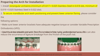
CONTENTS
• Introduction
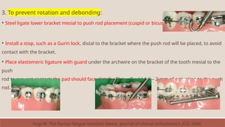
• History
•Mechanism of action
• Advantages of FFA over RFA
• Indications and contraindications of
FFA
• Classification of fixed functional
appliances
Rigid fixed functional appliances
Flexible fixed functional
appliances
Hybrid fixed functional
appliances
Conclusion
References
3.
3
P
A
R
T
o
n
e
• Introduction
• History
•Mechanism of action
• Advantages of FFA over RFA
• Indications and contraindications of FFA
• Classification of fixed functional appliances
• Rigid fixed functional appliances
Herbst Appliance and its Modifications
MARA
MPA
FMA
Biopedic appliance
Ritto appliance
5
Introduction
• Class IImalocclusion is one of the most common orthodontic
problems, and it occurs in about one third of the population.
• McNamara studied 277 children with class II malocclusion and
concluded that mandibular skeletal retrusion was the most common
characteristic, whereas maxillary skeletal protrusion was not a
common finding.
• A treatment approach aimed at modifying the direction and amount
of mandibular growth rather than restricting maxillary development
would therefore be indicated in many class II patients.
• This concept plays a primary role in functional jaw orthopedics.
6.
6
• Various functionalappliances have been developed over the past
century, removable and fixed.
• The main drawback of the removable appliances is that they require
very good patient cooperation.
• Due to noncompliance of the patient, which in general is increasing,
alternate treatment strategies of functional appliances had been
devised, broadly grouped as fixed functional appliances
7.
7
Historical Perspective
• NormanW. Kinsley who first (1879) used forward positioning of the
mandible in orthodontic treatment.
• Wilhelm Roux is credited as the first to study the influences of natural
forces and functional stimulation on form (1883) (Wolff ’s law).
• His work became the foundation of both general orthopedics and
functional dental orthopedic principles.
• Viggo Andresen’s Activator was the first functional appliance to gain the
widespread clinical use.
8.
8
Fixed functional appliancewas introduced by Dr. Emil Herbst of
Germany at the 5th International Dental Congress in Berlin in the year
1909 which was later discovered by Pancherz in the late 1970s.
The FFA has gone through evolutionary transition in design and uses
from its first version of rigid telescoping system (rigid fixed functional
appliance), that is Herbst appliance, followed by flexible versions
(flexible fixed functional appliance) to more recent appliance systems
which are relatively flexible, yet rigid enough (hybrid type) to sustain
forward mandibular position.
9.
9
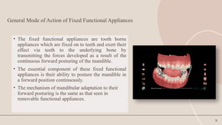
General Mode ofAction of Fixed Functional Appliances
• The fixed functional appliances are tooth borne
appliances which are fixed on to teeth and exert their
effect via teeth to the underlying bone by
transmitting the forces developed as a result of the
continuous forward posturing of the mandible.
• The essential component of these fixed functional
appliances is their ability to posture the mandible in
a forward position continuously.
• The mechanism of mandibular adaptation to their
forward posturing is the same as that seen in
removable functional appliances.
10.
10
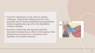
• From theexperiments on rats, Petrovic and his
colleagues claimed that enhanced activity in the
pterygoid muscle during mandibular hyper-propulsion
induced supplementary growth in the mandibular
condylar cartilage.
• Recently evidence has also been provided that
functional treatment has an effect on the location of the
glenoid fossa, giving rise to a relocation of the
mandible in an anterior direction.
11.
11
• The availableexperimental evidence therefore lends support to the
theoretical concept that functional appliance therapy indeed
dictates a "new pattern of function" leading to the development of
a correspondingly "new morphologic pattern".
• The new morphologic pattern "includes a different arrangement of
teeth within the jaws; an improvement of occlusion and an altered
relation of the jaws.
• It also includes changes in the amount and direction of growth of
the jaws and differences in facial size and proportions.
12.
12
• The hypothesisproposed by many clinicians that during first phase of
functional treatment, reflexes in jaw muscles are transiently brought into
a state of imbalance.
• The phase of imbalance could act as a trigger for the mandible to attain
a new functional position, subsequently leading to morphologic
changes.
• Usually the neuromuscular changes occur first and subsequently after an
interval of 2 weeks’ morphologic changes are seen.
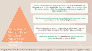
Moves the entiremandible anteroinferiorly. The anteroinferior
displacement of the mandibular dentition was most pronounced in
the incisor region, while the maxillary dentition was displaced
posterosuperiorly.
The displacement is more pronounced in the dentoalveolar region
as compared to the skeletal displacement.
All dentoalveolar structures experience tensile stresses, except
for anterior nasal spine and the maxillary posterior teeth.
Maximum tensile stress occurred in the condylar neck and
head. (Panigrahi and vineeth, 2009)
Biomechanical
Effects of Fixed
Functional
Appliance on
Craniofacial
Structures
Panigrahi P, Vineeth V. Biomechanical effects of fixed functional appliance on craniofacial structures. The Angle Orthodontist.
15.
15
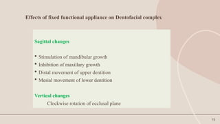
Effects of fixedfunctional appliance on Dentofacial complex
Sagittal changes
Stimulation of mandibular growth
Inhibition of maxillary growth
Distal movement of upper dentition
Mesial movement of lower dentition
Vertical changes
Clockwise rotation of occlusal plane
16.
16
Dental changes
• Themandibular teeth are moved anteriorly
• Mandibular incisors are proclined
• Maxillary teeth are moved posteriorly
• Maxillary teeth are distalized as well as intruded
17.
17
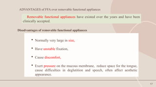
ADVANTAGES of FFAover removable functional appliances
Normally very large in size,
Have unstable fixation,
Cause discomfort,
Exert pressure on the mucous membrane, reduce space for the tongue,
cause difficulties in deglutition and speech, often affect aesthetic
appearance.
Removable functional appliances have existed over the years and have been
clinically accepted.
Disadvantages of removable functional appliances
18.
18
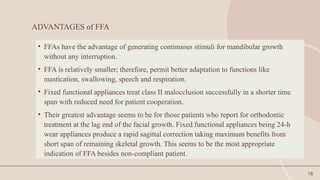
ADVANTAGES of FFA
•FFAs have the advantage of generating continuous stimuli for mandibular growth
without any interruption.
• FFA is relatively smaller; therefore, permit better adaptation to functions like
mastication, swallowing, speech and respiration.
• Fixed functional appliances treat class II malocclusion successfully in a shorter time
span with reduced need for patient cooperation.
• Their greatest advantage seems to be for those patients who report for orthodontic
treatment at the lag end of the facial growth. Fixed functional appliances being 24-h
wear appliances produce a rapid sagittal correction taking maximum benefits from
short span of remaining skeletal growth. This seems to be the most appropriate
indication of FFA besides non-compliant patient.
19.
19
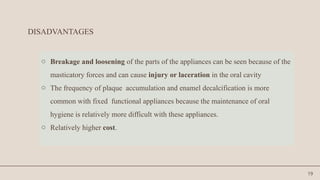
DISADVANTAGES
o Breakage andloosening of the parts of the appliances can be seen because of the
masticatory forces and can cause injury or laceration in the oral cavity
o The frequency of plaque accumulation and enamel decalcification is more
common with fixed functional appliances because the maintenance of oral
hygiene is relatively more difficult with these appliances.
o Relatively higher cost.
20.
20
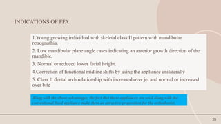
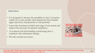
INDICATIONS OF FFA
1.Younggrowing individual with skeletal class II pattern with mandibular
retrognathia.
2. Low mandibular plane angle cases indicating an anterior growth direction of the
mandible.
3. Normal or reduced lower facial height.
4.Correction of functional midline shifts by using the appliance unilaterally
5. Class II dental arch relationship with increased over jet and normal or increased
over bite
Along with the above advantages, the fact that these appliances are used along with the
conventional fixed appliance make them an attractive proposition for the orthodontist.
21.
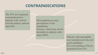
The FFA arein general
contraindicated in
patients with vertical
Growth pattern, anterior
open bite.
Most appliances cause
proclination of the
mandibular
Incisors, which may not be
desirable in subjects with
large IMPA.
Patients with susceptible
root resorption are also not
good candidates
For extra loading of forces
generated from FFA.
CONTRAINDICATIONS
20XX 21
22.
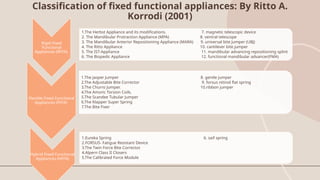
Classification of fixedfunctional appliances: By Ritto A.
Korrodi (2001)
Rigid Fixed
Functional
Appliances (RFFA)
1.The Herbst Appliance and its modifications. 7. magnetic telescopic device
2. The Mandibular Protraction Appliance (MPA) 8. ventral telescope
3. The Mandibular Anterior Repositioning Appliance (MARA) 9. universal bite jumper (UBJ)
4. The Ritto Appliance 10. cantilever bite jumper
5. The IST-Appliance 11. mandibular advancing repositioning splint
6. The Biopedic Appliance 12. functional mandibular advancer(FMA)
Flexible Fixed Functional
Appliances (FFFA)
1.The Jasper Jumper 8. gentle jumper
2.The Adjustable Bite Corrector 9. forsus nitinol flat spring
3.The Churro Jumper. 10.ribbon jumper
4.The Amoric Torsion Coils.
5.The Scandee Tubular Jumper
6.The Klapper Super Spring
7.The Bite Fixer
Hybrid Fixed Functional
Appliances (HFFA)
1.Eureka Spring 6. saif spring
2.FORSUS- Fatigue Resistant Device
3.The Twin Force Bite Corrector.
4.Alpern Class II Closers
5.The Calibrated Force Module
23.
presentation title 23
CONSIDERATIONSFOR FIXED FUNCTIONALAPPLIANCES
1)Age factor: fixed functional appliances have an important advantage that they can be
used in post adolescent patients in whom very less growth is remaining.
2)Growth considerations: The prognosis of the fixed functional therapy is poor in
patients with hyperdivergent facial growth patterns i.e. in patients with a large gonial
angle and increased lower anterior facial height and also in patients having an open
bite.
20XX
24.
presentation title 24
3)Estheticconsiderations: Fixed functional appliances yield excellent results in patients
with skeletal class II bases with retrognathic mandible who have a positive VTO (visual
treatment objective). On the contrary fixed functional appliances are not recommended in
patients with a negative VTO because of unsatisfactory results.
4)Compliance: Being fixed type of appliances they have an advantage that they do not
demand patient compliance which is an important factor in the success of removable type
of functional appliances.
20XX
25.
25
20XX
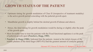
GROWTH STATUS OFTHE PATIENT
• Optimum timing for growth modulation of Class II (irrespective of treatment modality)
is the active growth period coinciding with the pubertal growth spurt.
• Mandibular growth is slightly behind the skeletal growth (Fishman and others).
• Hence, the ideal timing for growth modulation would be during or slightly after the peak
of the growth spurt.
• Most favorable time to treat the patients with the Fixed functional appliance is at the peak
of pubertal growth spurt (Pancherz, Hagg, 1985).
• Pancherz & Hagg (1988): Indicated that the patients treated at the initial closure of the
middle phalanx of the third finger (MP3-FG) had the greatest amount of condylar growth
(Sassouni 1972, Pearson 78, Pancherz 85, Malmgren 87, Baccetti 2000 ).
26.
presentation title 26
20XX
MODEOF ACTION
• The mechanism of mandibular adaptation to the forward posturing by fixed
functional appliance is the same as that seen in removable functional
appliance.
• The appliance is tooth-borne and exerts its effects via teeth to the
underlying bone by transmitting the forces developed as a result of the
continuous forward posturing of the lower jaw.
27.
presentation title 27
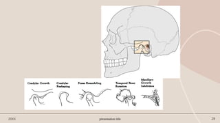
Inspiteof the various differences in concept, the general mode of action is one or combination of
the following
• Mandibular growth induction
• Maxillary growth restriction
• Dentoalveolar changes
• Glenoid fossa relocation
• Changes in neuromuscular anatomy and function.
• Typically, the results obtained by functional appliance in correction of class II malocclusion
consists of combination of orthopedic (30-40%) and dentoalveolar (60-70%) effects.
20XX
(Graber et al., 1997)
29
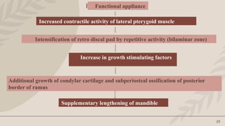
Functional appliance
Functional appliance
Increasedcontractile activity of lateral pterygoid muscle
Intensification of retro discal pad by repetitive activity (bilaminar zone)
Increase in growth stimulating factors
Additional growth of condylar cartilage and subperiosteal ossification of posterior
border of ramus
Supplementary lengthening of mandible
31
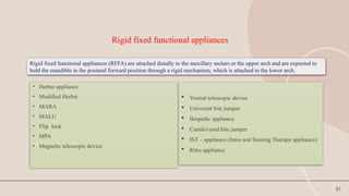
Rigid fixed functionalappliances
• Herbst appliance
• Modified Herbst
• MARA
• MALU
• Flip lock
• MPA
• Magnetic telescopic device
Ventral telescopic device
Universal bite jumper
Biopedic appliance
Cantilevered bite jumper
IST – appliance (Intra oral Snoring Therapy appliance)
Ritto appliance
Rigid fixed functional appliances (RFFA) are attached distally to the maxillary molars or the upper arch and are expected to
hold the mandible in the postural forward position through a rigid mechanism, which is attached to the lower arch.
33
The Herbst appliance
•The Herbst appliance, originally introduced by a German professor, Emil Herbst, as a
fixed bite-jumping device called Scharnier or Joint, at the International Dental
Congress in Berlin in 1905.
• After that very little was written on this appliance until the end of the 1970s when
Hans Pancherz reintroduced, researched and propagated this appliance.
• In the October 1979, Pancherz called attention to the possibilities of stimulating
mandibular growth by means of the Herbst appliance.
• The Herbst appliance is a fixed bite-jumping device for treatment of Class II
malocclusion. The Herbst appliance keeps the mandible continuously in a protruded
position both when the jaws close and when the teeth are not in occlusion, causing a
change in muscle function.
Pancherz H. The Herbst appliance—its biologic effects and clinical use. American journal of orthodontics. 1985 Jan 1;87(1):1-20.
34.
34
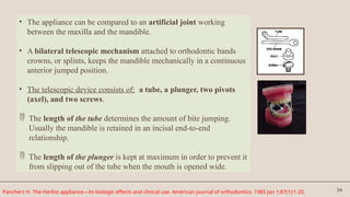
• The appliancecan be compared to an artificial joint working
between the maxilla and the mandible.
• A bilateral telescopic mechanism attached to orthodontic bands
crowns, or splints, keeps the mandible mechanically in a continuous
anterior jumped position.
• The telescopic device consists of: a tube, a plunger, two pivots
(axel), and two screws.
The length of the tube determines the amount of bite jumping.
Usually the mandible is retained in an incisal end-to-end
relationship.
The length of the plunger is kept at maximum in order to prevent it
from slipping out of the tube when the mouth is opened wide.
Pancherz H. The Herbst appliance—its biologic effects and clinical use. American journal of orthodontics. 1985 Jan 1;87(1):1-20.
35.
35
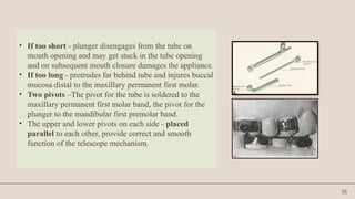
• If tooshort - plunger disengages from the tube on
mouth opening and may get stuck in the tube opening
and on subsequent mouth closure damages the appliance.
• If too long - protrudes far behind tube and injures buccal
mucosa distal to the maxillary permanent first molar.
• Two pivots –The pivot for the tube is soldered to the
maxillary permanent first molar band, the pivot for the
plunger to the mandibular first premolar band.
• The upper and lower pivots on each side - placed
parallel to each other, provide correct and smooth
function of the telescope mechanism.
36.
36
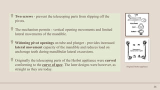
Two screws- prevent the telescoping parts from slipping off the
pivots.
The mechanism permits - vertical opening movements and limited
lateral movements of the mandible.
Widening pivot openings on tube and plunger - provides increased
lateral movement capacity of the mandible and reduces load on
anchorage teeth during mandibular lateral excursions.
Originally the telescoping parts of the Herbst appliance were curved
conforming to the curve of spee. The later designs were however, as
straight as they are today.
Originial Herbst applinace
37.
37
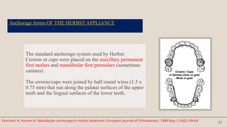
Anchorage forms OFTHE HERBST APPLIANCE
The standard anchorage system used by Herbst:
Crowns or caps were placed on the maxillary permanent
first molars and mandibular first premolars (sometimes
canines).
The crowns/caps were joined by half round wires (1.5 x
0.75 mm) that run along the palatal surfaces of the upper
teeth and the lingual surfaces of the lower teeth.
Pancherz H, Hansen K. Mandibular anchorage in Herbst treatment. European Journal of Orthodontics. 1988 May 1;10(2):149-64.
38.
38
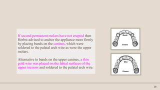
If second permanentmolars have not erupted then
Herbst advised to anchor the appliance more firmly
by placing bands on the canines, which were
soldered to the palatal arch wire as were the upper
molars.
Alternative to bands on the upper canines, a thin
gold wire was placed on the labial surfaces of the
upper incisors and soldered to the palatal arch wire.
39.
39
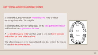
Early mixed dentitionanchorage system
In the maxilla, the permanent central incisors were used for
anchorage instead of the cuspids.
In the mandible , crowns were placed on the first permanent molars
and bands on the 4 permanent incisors.
A 1.2-mm thick gold wire was then used to join the lower incisors
and molars on their labial surfaces.
The telescoping axes were than soldered onto this wire in the region
of the first deciduous molars.
40.
40
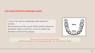
Late mixed dentitionanchorage system
Canines are used as anchorage teeth instead of
incisors.
Buccal mucosa at the corner of the mouth is prone to
ulceration when mandibular canine is used as an
abutment tooth for the plunger.
The necessity to incorporate as many teeth as
possible for anchorage to avoid unwanted side effects was realized early by Herbst.
41.
41
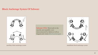
Schwarz( 1934): Mostteeth in the
maxilla and mandible were
interconnected by labial as well as
lingual arch wires( Block anchorage)
Block Anchorage System Of Schwarz
maxillary block anchorage system mandibular block anchorage system
42.
42
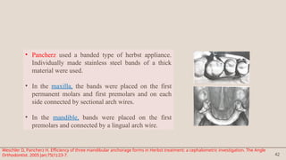
• Pancherz useda banded type of herbst appliance.
Individually made stainless steel bands of a thick
material were used.
• In the maxilla, the bands were placed on the first
permanent molars and first premolars and on each
side connected by sectional arch wires.
• In the mandible, bands were placed on the first
premolars and connected by a lingual arch wire.
Weschler D, Pancherz H. Efficiency of three mandibular anchorage forms in Herbst treatment: a cephalometric investigation. The Angle
Orthodontist. 2005 Jan;75(1):23-7.
43.
43
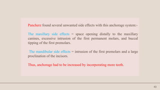
Pancherz found severalunwanted side effects with this anchorage system:-
The maxillary side effects = space opening distally to the maxillary
canines, excessive intrusion of the first permanent molars, and buccal
tipping of the first premolars.
The mandibular side effects = intrusion of the first premolars and a large
proclination of the incisors.
Thus, anchorage had to be increased by incorporating more teeth.
44.
44
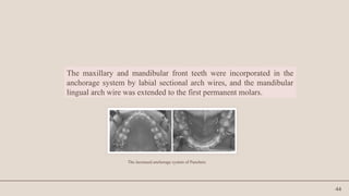
The maxillary andmandibular front teeth were incorporated in the
anchorage system by labial sectional arch wires, and the mandibular
lingual arch wire was extended to the first permanent molars.
The increased anchorage system of Pancherz
47
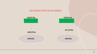
SAGITTAL CHANGES
Skeletal:
• 1.Restrainsmaxillary growth and decrease of SNA angle.
• 2. Increases mandibular length (Pancherz 1979, 1981, 1982).
This finding is in agreement with several bite jumping
experiments in growing monkeys (Stockle and Willert 1971,
McNamara 1972, 1973, 1975) and rats (Petrovic and Stutzman
1969).
Hansen K, Koutsonas T G, Pancherz H. l~ong-term effects of Herbst treatment on the mandibular incisor segment: a cephalometric and biometric investigation. AmJ
Orthod Dentolac Orthop 1997;112;92-103.
48.
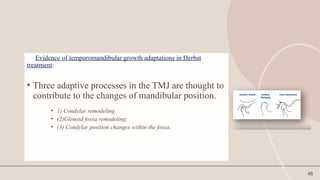
48
Evidence of temporomandibulargrowth adaptations in Herbst
treatment:
• Three adaptive processes in the TMJ are thought to
contribute to the changes of mandibular position.
• 1) Condylar remodeling.
• (2)Glenoid fossa remodeling;
• (3) Condylar position changes within the fossa.
49.
49
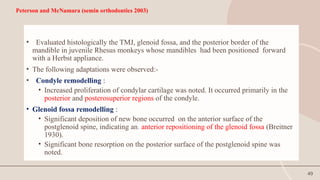
Peterson and McNamara(semin orthodontics 2003)
• Evaluated histologically the TMJ, glenoid fossa, and the posterior border of the
mandible in juvenile Rhesus monkeys whose mandibles had been positioned forward
with a Herbst appliance.
• The following adaptations were observed:-
• Condyle remodelling :
• Increased proliferation of condylar cartilage was noted. It occurred primarily in the
posterior and posterosuperior regions of the condyle.
• Glenoid fossa remodelling :
• Significant deposition of new bone occurred on the anterior surface of the
postglenoid spine, indicating an. anterior repositioning of the glenoid fossa (Breitner
1930).
• Significant bone resorption on the posterior surface of the postglenoid spine was
noted.
50.
50
• Significant bonyapposition on the posterior border of the mandibular
ramus was evident during early experimental periods.
• No gross or microscopic pathological changes were noted in TMJ of
the juvenile Rhesus monkey.
51.
51
Paulsen et al(1995) :
Analysed TMJ changes in a single case of Herbst treatment in late
puberty using CT scanning and OPG.
Three months after insertion of the appliance CT-scanning and OPGs
of the TMJ revealed new bone formation as a double contour in the
articular fossa and on the posterior part of the condylar process as a
result of adaptive bone remodeling.
52.
52
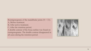
Roentgenograms of themandibular joints (N = 33).
A, Before treatment.
B, After active treatment.
C, After the retention period.
A double contour of the fossa outline was found on
roentgenograms. The double contour disappeared in
all cases during the retention period.
53.
53
Ruf and Pancherz(1998, 1999):
Analysed three possible adaptive TMJ growth processes contributing to
increase in mandibular prognathism accomplished by Herbst treatment :
Condylar remodeling
Glenoid fossa remodeling
Condyle fossa relationship changes.
Aidar, Abrahao ,Yamashita , Dominguez (AJO 2006) assesed the TMJ disc
position with MRI after 12 month period of herbst appliance therapy in 20
Class II div1 patients.
They found mild changes in position of the disc with slight tendency
towards retrusion due to mandibular advancement which returned to normal
after appliance removal. These changes were in the normal physiological
limits as evaluated in short term.
54.
54
Dental effects inSaggital direction
Dental changes seen during Herbst appliance treatment are
basically a result of anchorage loss in the two dental arches.
The telescope mechanism produces a posterior directed force on
the upper teeth and an anterior directed force on the lower teeth,
resulting in distal tooth movements in the maxillary buccal
segments and mesial tooth movements in the mandible.
55.
55
Mandibular teeth aremoved anteriorly
Proclination of lower anteriors. Mandibular incisors proclined on an average of 6.6
during 6 months (Pancherz, 1985). In 24 class II subjects treated with the Herbst
appliance (Hansen et al, 1997), the proclination during treatment was 11.
Mesial movements of lower molars
Maxillary molars are moved distally.
The effect of the Herbst appliance on maxillary molar teeth is essentially comparable
with that of a high pull headgear (Pancherz, Anechus- Pancherz, 1993). The teeth are
both distalized and intruded.
Normally, the dental changes occurring during Herbst appliance treatment would not
be desirable. Distal tooth movements in maxillary buccal segments could however, be
desirable in cases with anterior crowding.
56.
56
Sagittal dental archrelationship:
• Overjet is reduced in all patients during treatment by increase in
mandibular length and mesial movement (proclination) of the
mandibular incisors.
• Class II molar correction by increase in mandibular length, distal
movement of maxillary molars and mesial movement of the
mandibular molars.
57.
57
Herbst appliance correctsor overcorrects both molar & canine sagittal
relation in most of the cases.
However treatment is more effective in the molar than in the canine region.
This is probably due to the maxillary anchorage system, the molar connected
to the first premolar, is pushed distally by the telescope mechanism
(Pancherz and Hansen 1986). The canine, on the other hand, is not directly
engaged in the anchorage system.
58.
58
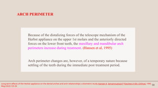
Because of thedistalizing forces of the telescope mechanism of the
Herbst appliance on the upper 1st molars and the anteriorly directed
forces on the lower front teeth, the maxillary and mandibular arch
perimeters increase during treatment. (Hansen et al, 1995)
Arch perimeter changes are, however, of a temporary nature because
settling of the teeth during the immediate post treatment period.
ARCH PERIMETER
Long-term effects of the Herbst appliance on the dental arches and arch relationships: a biometric study.Hansen K, Iemamnueisuk P Pancherz H Br J Orthod. 1995
May;22(2):123-34
59.
59
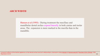
Hansen et al(1995) : During treatment the maxillary and
mandibular dental arches expand laterally in both canine and molar
areas. The expansion is more marked in the maxilla than in the
mandible.
ARCH WIDTH
Long-term effects of the Herbst appliance on the dental arches and arch relationships: a biometric study.Hansen K, Iemamnueisuk P Pancherz H Br J Orthod. 1995
May;22(2):123-34
60.
60
SKELETAL CHANGES INVERTICAL DIRECTION
Increase in lower anterior facial height (LAFH) due to over eruption of
lower posterior teeth.
Increase in gonial angle – this may be due to a more sagittaly directed
growth of the condyle or it may result from resorptive bone changes in the
gonion region, probably as a consequence of an altered muscle function
during bite jumping (Pancherz & Littman, 1989)
61.
61
DENTAL CHANGES INVERTICAL
DIRECTION
In Class II malocclusions with deep bites, overbite may be reduced
significantly by Herbst therapy (Pancherz, 1982, 1985) an average of
3.0mm (55%) during 6 months of treatment.
Overbite reduction is primarily accomplished by intrusion of lower
incisors and enhanced eruption of lower molars.
Part of the registered changes in the vertical position of the mandibular
incisors results from proclination of these teeth.
62.
62
Indications of Herbsttreatment
Pancherz (AJO Jan 1985); indicated that Herbst appliance should be used only in
growing individuals.
Postadolescent patients:
Who have passed the maximum pubertal growth spurt and have still some growth
potential left, treatment with the Herbst appliance is indicated as it can be finished
within 6 to 8 months.
Uncooperative patients: It is fixed to the teeth without any assistance from the patient.
Mouth breathers: Nasal airway obstructions can make the proper use of removable
appliances difficult or impossible but doesn’t interfere with herbst.
63.
63
Should notbe used in non growing subjects because:
1. Skeletal alterations will be minimal.
2. More of dentoalveolar changes.
3. Increase risk of developing dual bite.
64.
64
TIMING OF TREATMENT
•In all Herbst studies assessing the interrelation between somatic or skeletal
maturity and mandibular growth stimulation, a large interindividual variation
exists.
• Nevertheless, a general pattern could be identified showing a Steady increase
in sagittal condylar growth stimulation from the prepeak to the peak growth
period, followed by a steady decline in the postpeak period.
• Subjects treated at peak or 1 to 2 years after peak exhibited the largest sagittal
condylar growth and thus the largest mandibular length increase.
Sabine Ruf, Hans Pancherz: When is the ideal period for Herbst therapy-Early or Late? Semin Orthod 2003,March.47-56
65.
65
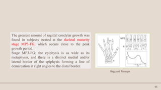
The greatest amountof sagittal condylar growth was
found in subjects treated at the skeletal maturity
stage MP3-FG, which occurs close to the peak
growth period.
Stage MP3-FG: the epiphysis is as wide as its
metaphysis, and there is a distinct medial and/or
lateral border of the epiphysis forming a line of
demarcation at right angles to the distal border.
Hagg and Taranger
66.
66
• It isbelieved that Class II correction by orthopaedic means is not possible after the
age of 13.5 years in girls and 15 years in boys because 97% of the growth is
completed at these ages.
• However, in using the Herbst appliance, it is possible to reactivate and stimulate
condylar growth even in subjects at the end of growth.
• Although the total amount of mandibular length increase in young adults (skeletal
maturity stages R-IJ or RJ ) is less than in adolescents, the amount of stimulated
mandibular growth is identical.
• This implies that young adult Class II subjects can be treated successfully by means
of the Herbst appliance. Thus, the treatment method could be considered to be an
alternative to orthognathic surgery
67.
67
TREATMENT CONSIDERATIONS
As arule, Class II cases cannot be treated to a perfect end result with the Herbst appliance
exclusively.
Many cases will require a subsequent dental alignment treatment phase with a multibracket
appliance.
Thus, A Class II, Division 1 malocclusion requires a two-step treatment approach:
• STEP 1. ORTHOPEDIC PHASE. The sagittal jaw base relationship is normalized and the
Class II malocclusion is transferred to a Class I malocclusion by means of the Herbst
appliance.
• STEP 2. ORTHODONTIC PHASE. Tooth irregularities and arch discrepancy problems are
treated with a multibracket appliance (with or without extractions of teeth).
68.
68
A Class II,Division 2 malocclusion may require a three-step treatment
approach
• STEP 1. ORTHODONTIC PHASE. Alignment of the anterior maxillary
teeth by means of a multibracket orthodontic appliance.
• STEP 2. ORTHOPEDIC PHASE. Normalization of sagittal jaw base
relationships and transformation of the Class II malocclusion into a Class
I malocclusion by means of the Herbst appliance.
• STEP 3. ORTHODONTIC PHASE. Tooth irregularities and arch-
discrepancy problems are treated with a multibracket appliance (with or
without extractions of teeth).
69.
69
RETENTION AFTER HERBSTAPPLIANCE TREATMENT
Needs a stable cuspal interdigitation to counteract occlusal relapse.
• Relapse in dental arch relationships after treatment - results from dental changes in maxilla and
mandible and/or from an unfavorable growth development. Treatment performed in the
mixed dentition necessitates retention until permanent teeth have erupted and the occlusion is
stabilized.
• Pancherz and Fackel (Wieslander 1993) investigated group of Herbst cases during the 2½
years pre treatment, during treatment, and 2½ years post treatment. They showed post-
orthopedic treatment period; maxillary and mandibular growth appears to return to their
earlier patterns.
• A clinically significant effect was found 2½ years post treatment and despite most parameters
displaying relapse tendencies, a stable functional occlusion seemed to counteract occlusal
relapse.
70.
70
TYPES of HerbstApplianace
The original design since the seventies has maintained its
general shape with only a few modifications taking place
with regard to methods of application (Type I, II and IV).
71.
71
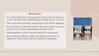
Herbst type I
•It is characterized by a fixing system to the crowns or bands or
to the wire framework (splint design) through the use of screws.
• This is the most commonly used design of the Herbst appliance.
• It is necessary to solder the axles to the molar bands or crowns,
and then fix the tubes and plungers with the screws.
• Herbst appliance does not permit lateral jaw movements.
• It is extremely difficult to place the right and left axles in
alignment, which makes them susceptible to breakages.
72.
72
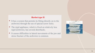
Herbst type II
It has a system that permits its fitting directly on to the
archwires through the use of special screw locks.
The rigid appliance, which is fixed on relatively less
rigid archwires, has several drawbacks.
It causes difficulties in lateral movements of the jaw and
stress fracture of the archwires is common.
73.
73
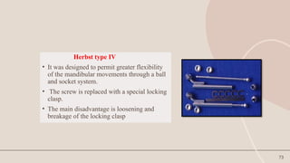
Herbst type IV
•It was designed to permit greater flexibility
of the mandibular movements through a ball
and socket system.
• The screw is replaced with a special locking
clasp.
• The main disadvantage is loosening and
breakage of the locking clasp
75
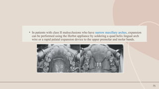
• In patientswith class II malocclusions who have narrow maxillary arches, expansion
can be performed using the Herbst appliance by soldering a quad helix lingual arch
wire or a rapid palatal expansion device to the upper premolar and molar bands.
76.
76
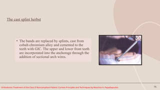
The cast splintherbst
• The bands are replaced by splints, cast from
cobalt-chromium alloy and cemented to the
teeth with GIC. The upper and lower front teeth
are incorporated into the anchorage through the
addition of sectional arch wires.
Orthodontic Treatment of the Class II Noncompliant Patient: Current Principles and Techniques by Moschos A. Papadopoulos
77.
77
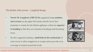
The Herbst withcrowns – Langford design
• Norris M. Langford, (1982 JCO) suggested using stainless
steel crowns on the upper first molar and the lower first
premolar or canine for the Herbst appliance which are superior
to banding in that they are resistant to breakage and becoming
loose.
• He also suggested making a small hole in the occlusal pit of
each crown to allow trapped air to escape and to provide even
coverage of cement around the tooth.
Orthodontic Treatment of the Class II Noncompliant Patient: Current Principles and Techniques by Moschos A. Papadopoulos
78.
78
Bonded Herbst appliance
•Introduced by Raymond P. Howe, 1982, to over come some of the
limitations of the original banded appliance.
o limitation of the appliance to patients with erupted mandibular
first bicuspid.
o repeated breakage and loosening of the appliance .
o rapid intrusion of the mandibular first bicuspid which though
temporary, partially deactivates the appliance.
o as the bicuspids are depressed the lingual arch is also depressed
resulting in impingement of the lingual gingiva.
o possibility of incisal tooth fracture
(Raymond P Howe : The Bonded Herbst Appliance JCO 1982, Oct: 663 – 667 )
79.
79
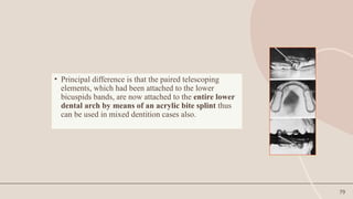
• Principal differenceis that the paired telescoping
elements, which had been attached to the lower
bicuspids bands, are now attached to the entire lower
dental arch by means of an acrylic bite splint thus
can be used in mixed dentition cases also.
80.
80
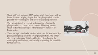
• Short, stiffcoil springs (.020" spring wire) 3mm long, with an
inside diameter slightly larger than the plunger shaft, can be
placed between the upper and lower telescoping elements .
• They are designed to provide a dampening effect as the
plungers sleeves contact upon closure. This may reduce
shock-induced loosening of either the upper bands or the
lower splint.
• These springs can also be used to reactivate the appliance. By
placing the springs over the lower plunger shafts, the upper
sleeves are displaced distally, effectively lengthening the
telescoping mechanisms, and thereby advancing the mandible
farther forward.
81.
81
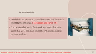
The Acrylic SplintHerbst
• Bonded Herbst appliance eventually evolved into the acrylic
splint Herbst appliance. ( McNamara and Howe ’88)
• It is composed of a wire framework over which has been
adapted , a 2.5-3 mm thick splint Biocryl, using a thermal
pressure machine.
Orthodontic Treatment of the Class II Noncompliant Patient: Current Principles and Techniques by Moschos A. Papadopoulos
82.
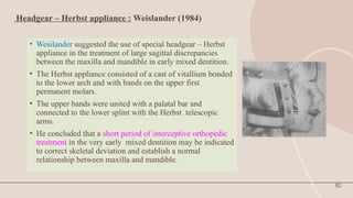
Headgear – Herbstappliance : Weislander (1984)
• Wesilander suggested the use of special headgear – Herbst
appliance in the treatment of large sagittal discrepancies
between the maxilla and mandible in early mixed dentition.
• The Herbst appliance consisted of a cast of vitallium bonded
to the lower arch and with bands on the upper first
permanent molars.
• The upper bands were united with a palatal bar and
connected to the lower splint with the Herbst telescopic
arms.
• He concluded that a short period of interceptive orthopedic
treatment in the very early mixed dentition may be indicated
to correct skeletal deviation and establish a normal
relationship between maxilla and mandible.
82
83.
83
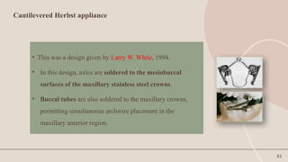
Cantilevered Herbst appliance
•This was a design given by Larry W. White, 1994.
• In this design, axles are soldered to the mesiobuccal
surfaces of the maxillary stainless steel crowns.
• Buccal tubes are also soldered to the maxillary crowns,
permitting simultaneous archwire placement in the
maxillary anterior region.
84.
84
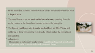
In themandible, stainless steel crowns on the Ist molars are connected with
a lingual arch.
The mandibular axles are soldered to buccal wires extending from the
molar crowns to the buccal embrasures between the bicuspids.
The buccal cantilever wire is made by doubling on 0.045” wire and
soldering is done between the two strands, which makes the wire almost
unbreakable.
Advantage :
This design is particularly useful when mandibular bicuspids are absent or
the primary molars cannot withstand functional forces.
85.
85
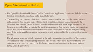
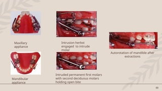
Open Bite IntrusionHerbst
• The Open-Bite Intrusion Herbst (AOA/Pro Orthodontic Appliances, Sturtevant, WI) for mixed
dentition consists of a maxillary and a mandibular part.
• The maxillary part consists of crowns cemented on the maxillary second deciduous molars
and permanent first molars, stops which extend from the deciduous second molars to the
deciduous first molars, 0.036′′ stainless steel intrusion wires with helix loops soldered to the
deciduous second molars to intrude the maxillary permanent first molars, cantilever extensions
with 0.022′′ archwire tubes soldered to the deciduous second molar crowns, and positioning
axles distal to the deciduous second molar crowns and just mesial to the permanent first molar
crowns.
• The telescopic axles are initially soldered to the axles to maintain the position of the primary
second molars while intruding the permanent first molars, while axles positioned to the first
molar crowns are used to connect the Herbst mechanism and maintain the intruded molars
during Class II correction.
86.
86
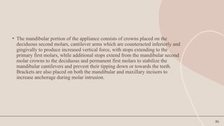
• The mandibularportion of the appliance consists of crowns placed on the
deciduous second molars, cantilever arms which are counteracted inferiorly and
gingivally to produce increased vertical force, with stops extending to the
primary first molars, while additional stops extend from the mandibular second
molar crowns to the deciduous and permanent first molars to stabilize the
mandibular cantilevers and prevent their tipping down or towards the teeth.
Brackets are also placed on both the mandibular and maxillary incisors to
increase anchorage during molar intrusion.
87.
87
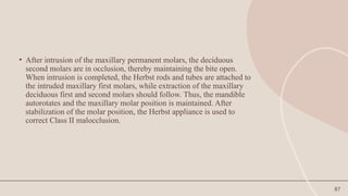
• After intrusionof the maxillary permanent molars, the deciduous
second molars are in occlusion, thereby maintaining the bite open.
When intrusion is completed, the Herbst rods and tubes are attached to
the intruded maxillary first molars, while extraction of the maxillary
deciduous first and second molars should follow. Thus, the mandible
autorotates and the maxillary molar position is maintained. After
stabilization of the molar position, the Herbst appliance is used to
correct Class II malocclusion.
89
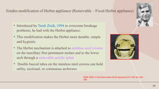
Emden modification ofHerbst appliance (Removable – Fixed Herbst appliance)
• Introduced by Tarek Zreik, 1994 to overcome breakage
problems, he had with the Herbst appliance.
• This modification makes the Herbst more durable, simple
and hygienic.
• The Herbst mechanism is attached to stainless steel crowns
on the maxillary first permanent molars and to the lower
arch through a removable acrylic splint.
• Double buccal tubes on the stainless steel crowns can hold
utility, sectional, or continuous archwires.
TAREK ZREIK: A Fixed-Removable Herbst Appliance JCO 1994 Apr 246 –
248)
90.
90
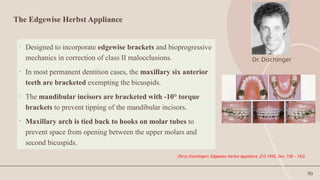
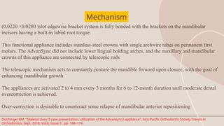
The Edgewise HerbstAppliance
• Designed to incorporate edgewise brackets and bioprogressive
mechanics in correction of class II malocclusions.
• In most permanent dentition cases, the maxillary six anterior
teeth are bracketed exempting the bicuspids.
• The mandibular incisors are bracketed with -10° torque
brackets to prevent tipping of the mandibular incisors.
• Maxillary arch is tied back to hooks on molar tubes to
prevent space from opening between the upper molars and
second bicuspids.
(Terry Dischingerl: Edgewise Herbst Appliance JCO 1995, Dec: 738 – 742)
Dr. Dischinger
91.
91
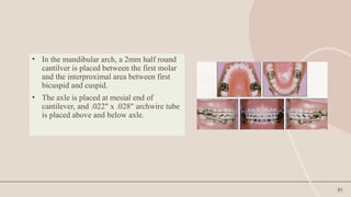
• In themandibular arch, a 2mm half round
cantilver is placed between the first molar
and the interproximal area between first
bicuspid and cuspid.
• The axle is placed at mesial end of
cantilever, and .022" x .028" archwire tube
is placed above and below axle.
92.
92
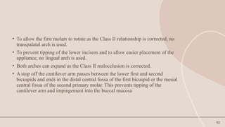
• To allowthe first molars to rotate as the Class II relationship is corrected, no
transpalatal arch is used.
• To prevent tipping of the lower incisors and to allow easier placement of the
appliance, no lingual arch is used.
• Both arches can expand as the Class II malocclusion is corrected.
• A stop off the cantilever arm passes between the lower first and second
bicuspids and ends in the distal central fossa of the first bicuspid or the mesial
central fossa of the second primary molar. This prevents tipping of the
cantilever arm and impingement into the buccal mucosa
93.
93
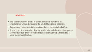
Advantages:
1. There areno lingual wires to interfere with the tongue, and no forward tipping force on the
lower incisors.
2. The lower arch can expand along with the upper arch.
3. Recementation is easy if a crown is loosened.
4. There is a lip bumper effect.
5. One lower bicuspid and lower cuspid on each side are free to erupt.
6. In the permanent dentition, the cantilever is lower in the vestibule than previously,
resulting in less lip irritation. Being longer, the rod and tube assembly tends to disengage
less on opening. In the mixed dentition, the cantilever is higher to prevent impingement
into the vestibular tissue.
7. The .019" .025" CuNiTi wire eliminates the need to change archwires during Herbst
treatment.
8. The use of negative-torque brackets and the position of the archwire tube on the axle allow
the mandibular arch to be leveled with just a straight archwire
94.
94
• Disadvantages:
1. Thereis more chance of interference with the rods and tubes and the
cantilever arm on opening and closing.
2. If the stops are not properly positioned, the molar can tip and the crown may
impinge on tissue.
3. There is a greater chance that the occlusion may dislodge a lower incisor
bracket
95.
95
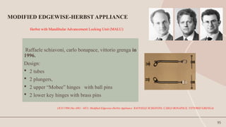
Herbst with MandibularAdvancement Locking Unit (MALU)
Raffaele schiavoni, carlo bonapace, vittorio grenga in
1996.
Design:
2 tubes
2 plungers,
2 upper “Mobee” hinges with ball pins
2 lower key hinges with brass pins
MODIFIED EDGEWISE-HERBST APPLIANCE
(JCO 1996 Dec (681 - 687): Modified Edgewise-Herbst Appliance RAFFAELE SCHIAVONI, CARLO BONAPACE, VITTORIO GRENGA)
96.
96
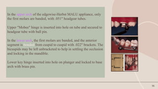
In the upperarch of the edgewise-Herbst MALU appliance, only
the first molars are banded, with .051" headgear tubes.
Upper "Mobee" hinge is inserted into hole on tube and secured to
headgear tube with ball pin.
In the lower arch, the first molars are banded, and the anterior
segment is bonded from cuspid to cuspid with .022" brackets. The
bicuspids may be left unbracketed to help in settling the occlusion
and locking in the mandible.
Lower key hinge inserted into hole on plunger and locked to base
arch with brass pin.
97.
97
• An .021"x .025" stainless steel archwire with slight labial root torque in the
anterior segment is bent back tightly at the distal ends.
• The length of the tube-plunger assembly is adjusted according to the amount of
mandibular protrusion needed. The mandible can be progressively advanced
using 1-5mm spacers.
98.
98
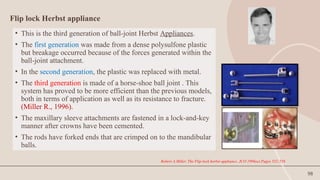
Flip lock Herbstappliance
• This is the third generation of ball-joint Herbst Appliances.
• The first generation was made from a dense polysulfone plastic
but breakage occurred because of the forces generated within the
ball-joint attachment.
• In the second generation, the plastic was replaced with metal.
• The third generation is made of a horse-shoe ball joint . This
system has proved to be more efficient than the previous models,
both in terms of application as well as its resistance to fracture.
(Miller R., 1996).
• The maxillary sleeve attachments are fastened in a lock-and-key
manner after crowns have been cemented.
• The rods have forked ends that are crimped on to the mandibular
balls.
Robert A.Miller. The Flip-lock herbst appliance. JCO 1996oct.Pages 552-558
99.
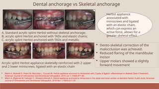
Dental anchorage vsSkeletal anchorage
A, Standard acrylic splint Herbst without skeletal anchorage;
B, acrylic splint Herbst anchored with TADs and elastic chains;
C, acrylic splint Herbst anchored with TADs and metallic
Herbst appliance
associated with
miniscrews and ligated
with an elastic chain,
which can express an
active force, allows for a
greater skeletal effect
Acrylic splint Herbst appliance skeletally reinforced with 2 upper
and 2 lower miniscrews, ligated with an elastic chain
Dento-skeletal correction of the
malocclusion was achieved.
Reduced flaring of the mandibular
incisor
Upper molars showed a slightly
forward movement
Manni A, Mutinelli S, Pasini M, Mazzotta L, Cozzani M. Herbst appliance anchored to miniscrews with 2 types of ligation: effectiveness in skeletal Class II treatment.
American Journal of Orthodontics and Dentofacial Orthopedics. 2016 Jun 1;149(6):871-80.
Manni A, Migliorati M, Calzolari C, Silvestrini-Biavati A. Herbst appliance anchored to miniscrews in the upper and lower arches vs standard Herbst: A pilot study. American
Journal of Orthodontics and Dentofacial Orthopedics. 2019 Nov 1;156(5):617-25.
100.
100
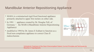
Mandibular Anterior RepositioningAppliance
• MARA is a miniaturised rigid fixed functional appliance
primarily attached to upper first molars on either side.
• In 1991 appliance created by Dr. Douglas Toll, of
Germany the MARA (Mandibular Anterior Repositioning
Appliance)
• modified in 1994 by Dr. James E Eckhart to function as a
fixed non-compliance appliance to correct Class II
malocclusions
Orthodontic Treatment of the Class II Noncompliant Patient: Current Principles and Techniques by
Moschos A. Papadopoulos
101.
101
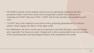
• The MARAconsists of four stainless steel crowns (or rigid bands) attached to the first
permanent molars. Each lower molar crown incorporates a double tube soldered on it,
consisting of a 0.045′′ tube and a 0.022 × 0.028′′ tube for the maxillary and mandibular arch
wires.
• A 0.059′′ arm is also soldered to each lower crown, projecting perpendicular to its buccal
surface, which engages the elbows of the upper molar.
• For stabilization, the lower crowns can be connected to each other through a soldered lingual
arch, especially if no braces are used. A lingual arch is also recommended to prevent crowding
of the second premolars and mesiolingual rotation of the mandibular first molars
102.
102
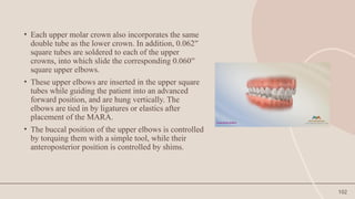
• Each uppermolar crown also incorporates the same
double tube as the lower crown. In addition, 0.062′′
square tubes are soldered to each of the upper
crowns, into which slide the corresponding 0.060′′
square upper elbows.
• These upper elbows are inserted in the upper square
tubes while guiding the patient into an advanced
forward position, and are hung vertically. The
elbows are tied in by ligatures or elastics after
placement of the MARA.
• The buccal position of the upper elbows is controlled
by torquing them with a simple tool, while their
anteroposterior position is controlled by shims.
103.
103
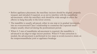
• Before applianceplacement, the maxillary incisors should be aligned, properly
torqued, and intruded if required, so as not to interfere with the mandibular
advancement, while the maxillary arch should be wide enough to allow the
elbows to hang buccally to the lower crowns.
• The mandible is usually advanced, either in one step or in gradual increments,
into an overcorrected Class I relationship to counteract the expected small
relapse usually observed during the posttreatment period.
• When 4–5 mm of mandibular advancement is required, the mandible is
advanced to an edge-to-edge incisor position. When 8–9 mm correction is
needed, the advancement is performed in two steps to avoid excessive strain on
the temporomandibular joint or appliance breakage
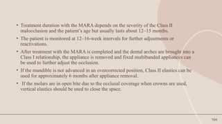
104.
104
• Treatment durationwith the MARA depends on the severity of the Class II
malocclusion and the patient’s age but usually lasts about 12–15 months.
• The patient is monitored at 12–16-week intervals for further adjustments or
reactivations.
• After treatment with the MARA is completed and the dental arches are brought into a
Class I relationship, the appliance is removed and fixed multibanded appliances can
be used to further adjust the occlusion.
• If the mandible is not advanced in an overcorrected position, Class II elastics can be
used for approximately 6 months after appliance removal.
• If the molars are in open bite due to the occlusal coverage when crowns are used,
vertical elastics should be used to close the space.
105.
105
• The aimof this study was to investigate the MARA's dental and skeletal
effects on anterior, posterior, and vertical changes in 30 Class II patients.
• The treatment group consisted of 12 boys with an average age of 11.2 years
and 18 girls with an average age of 11.3 years.
• A pretreatment cephalometric radiograph was taken 2 weeks before
treatment, and a posttreatment cephalometric radiograph was taken 6 weeks
after removal of the MARA, with an average treatment time of 10.7 months.
106.
106
• The resultsof the study showed that the MARA produced measurable treatment
effects on the skeletal and dental elements of the craniofacial complex.
• These effects included a considerable distalization of the maxillary molar, a
measurable forward movement of the mandibular molar and incisor, a significant
increase in mandibular length, and an increase in posterior face height.
• The effects of the MARA treatment were then compared with those of the Herbst
and Frankel appliances.
• The treatment results of the MARA were very similar to those produced by the
Herbst appliance but with less headgear effect on the maxilla and less mandibular
incisor proclination than observed in the Herbst treatment group
107.
107
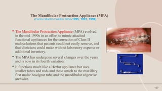
The Mandibular ProtractionAppliance (MPA)
(Carlos Martin Coelho Filho-1995, 1997, 1998)
The Mandibular Protraction Appliance (MPA) evolved
in the mid 1990s in an effort to mimic attached
functional appliances for the correction of Class II
malocclusions that patients could not easily remove, and
that clinicians could make without laboratory expense or
additional inventory.
The MPA has undergone several changes over the years
and is now in its fourth variation.
It functions much like a Herbst appliance but uses
smaller tubes and rods and these attach to the maxillary
first molar headgear tube and the mandibular edgewise
archwire.
108.
108
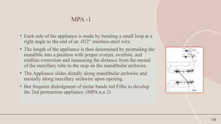
MPA -1
• Eachside of the appliance is made by bending a small loop at a
right angle to the end of an .032" stainless steel wire.
• The length of the appliance is then determined by protruding the
mandible into a position with proper overjet, overbite, and
midline correction and measuring the distance from the mesial
of the maxillary tube to the stop on the mandibular archwire.
• The Appliance slides distally along mandibular archwire and
mesially along maxillary archwire upon opening.
• But frequent dislodgment of molar bands led Filho to develop
the 2nd protraction appliance. (MPA n.o 2)
109.
109
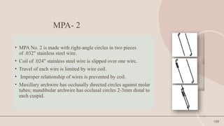
MPA- 2
• MPANo. 2 is made with right-angle circles in two pieces
of .032" stainless steel wire.
• Coil of .024" stainless steel wire is slipped over one wire.
• Travel of each wire is limited by wire coil.
• Improper relationship of wires is prevented by coil.
• Maxillary archwire has occlusally directed circles against molar
tubes; mandibular archwire has occlusal circles 2-3mm distal to
each cuspid.
110.
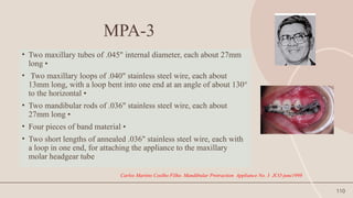
110
MPA-3
• Two maxillarytubes of .045" internal diameter, each about 27mm
long •
• Two maxillary loops of .040" stainless steel wire, each about
13mm long, with a loop bent into one end at an angle of about 130°
to the horizontal •
• Two mandibular rods of .036" stainless steel wire, each about
27mm long •
• Four pieces of band material •
• Two short lengths of annealed .036" stainless steel wire, each with
a loop in one end, for attaching the appliance to the maxillary
molar headgear tube
Carlos Martins Coelho Filho. Mandibular Protraction Appliance No. 3 JCO june1998
111.
111
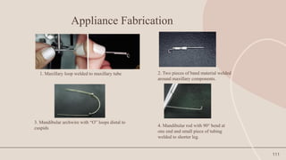
Appliance Fabrication
1. Maxillaryloop welded to maxillary tube 2. Two pieces of band material welded
around maxillary components.
3. Mandibular archwire with “O” loops distal to
cuspids
4. Mandibular rod with 90° bend at
one end and small piece of tubing
welded to shorter leg.
112.
112
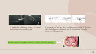
5. Mandibular rodinserted through “O” loop of
archwire and manipulated upward.
6. Annealed .036" pin bent down mesial to headgear tube. B. Maxillary
tube attached mesial to headgear tube. C. Annealed pin inserted at
mesial end of headgear tube
Class II patient with MPA No. 3 in place, showing maximum opening
113.
113
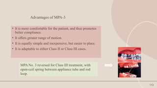
Advantages of MPA-3
•It is more comfortable for the patient, and thus promotes
better compliance.
• It offers greater range of motion.
• It is equally simple and inexpensive, but easier to place.
• It is adaptable to either Class II or Class III cases.
MPA No. 3 reversed for Class III treatment, with
open-coil spring between appliance tube and rod
loop.
114.
114
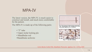
MPA-IV
The latest version,the MPA IV, is much easier to
construct and install, and much more comfortable
for the patient.
The MPA IV is made up of the following parts:
• “T” tube
• Upper molar locking pin
• Mandibular rod
•Mandibular archwire
Carlos Martins Coelho Filho. Mandibular Protraction Appliance No. 4 JCO jan2001
115.
115
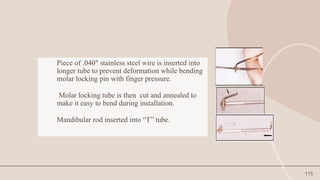
Piece of .040"stainless steel wire is inserted into
longer tube to prevent deformation while bending
molar locking pin with finger pressure.
Molar locking tube is then cut and annealed to
make it easy to bend during installation.
Mandibular rod inserted into “T” tube.
116.
116
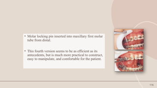
• Molar lockingpin inserted into maxillary first molar
tube from distal.
• This fourth version seems to be as efficient as its
antecedents, but is much more practical to construct,
easy to manipulate, and comfortable for the patient.
117.
117
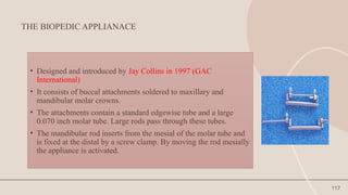
THE BIOPEDIC APPLIANACE
•Designed and introduced by Jay Collins in 1997 (GAC
International)
• It consists of buccal attachments soldered to maxillary and
mandibular molar crowns.
• The attachments contain a standard edgewise tube and a large
0.070 inch molar tube. Large rods pass through these tubes.
• The mandibular rod inserts from the mesial of the molar tube and
is fixed at the distal by a screw clamp. By moving the rod mesially
the appliance is activated.
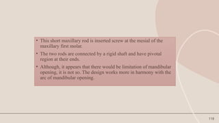
118.
118
• This shortmaxillary rod is inserted screw at the mesial of the
maxillary first molar.
• The two rods are connected by a rigid shaft and have pivotal
region at their ends.
• Although, it appears that there would be limitation of mandibular
opening, it is not so. The design works more in harmony with the
arc of mandibular opening.
119.
119
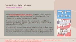
Functional Mandibular Advancer
Kinzinger,Ostheimer, Diederich,2002
• The Functional Mandibular Advancer (FMA) is a new, rigid and
fixed appliance for sagittal correction of the intermaxilary jaw
relationship in adolescents and young adults.
• It has a propulsive mechanism that resembles the Mandibular
anterior repositioning appliance, but differs in its mode of action
and intraoral activation.
• It incorporates the basic mechanical principle of the inclined planes.
• Its essential elements are protrusive bars and inclined planes, which
are fixed bilaterally to the vestibular surfaces of the posterior teeth.
Kinzinger G, Ostheimer J, Förster F, Kwandt PB, Reul H, Diedrich P. Development of a new fixed functional appliance for treatment
of skeletal class II malocclusion first report. J Orofac Orthop. 2002 Sep;63(5):384-99.
120.
120
• The protrusivebars of the FMA are placed at an angle of approx. 60
degrees to the horizontal plane thereby actively guiding the
mandible anteriorly during jaw closure.
• Reactivation in the sagittal plane is done simply by moving the
guide pins to a more forward threaded support sleeve. This gradual
activation allows patients particularly adults to adjust to the
appliance.
121.
121
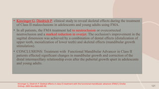
• Kinzinger G,Diedrich P. clinical study to reveal skeletal effects during the treatment
of Class II malocclusions in adolescents and young adults using FMA.
• In all patients, the FMA treatment led to neutroclusion or overcorrected
neutroclusion and a marked reduction in overjet. The occlusion's improvement in the
sagittal dimension was achieved by a combination of dental effects (distalization of
upper teeth, mesialization of lower teeth) and skeletal effects (mandibular growth
stimulation).
• CONCLUSIONS: Treatment with Functional Mandibular Advancer in Class II
patients effected significant changes in mandibular growth and correction of the
distal intermaxillary relationship even after the pubertal growth spurt in adolescents
and young adults.
Kinzinger G, Diedrich P. Skeletal effects in class II treatment with the functional mandibular advancer (FMA)? J Orofac
Orthop. 2005 Nov;66(6):469-90.
122.
122
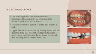
THE RITTO APPLIANCE
•The Ritto Appliance can be described as a
miniaturized telescopic device with simplified
intraoral application and activation.
• Fixation accessories consist of a steel ball pin and a
lock.
• Upper fixation is carried out by placing a steel ball pin
from the distal into the .045 headgear tube on the
upper molar band, through the appliance eyelet and
then bending it back on the mesial end.
123.
123
• The applianceis fixed onto a prepared lower arch and
is activated by sliding the lock along the lower arch in
the distal direction and then fixing it against the Ritto
Appliance.
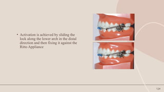
124.
124
• Activation isachieved by sliding the
lock along the lower arch in the distal
direction and then fixing it against the
Ritto Appliance
125.
125
• It facilitatesthe mandible forward thus creating constant orthopedics
changes as tested and demonstrated by clinical researches.
• Simple anad streamlined designed, easy to deliver for doctor.
• No TPA and lingual arches required
• Allow freedom of process mesial to the molar crowns
• Built in activation –no need to change the arms for final activation.
Advantages:
128
FLEXIBLE FIXED FUNCTIONALAPPLIANCES
•Can be described as an inter-maxillary torsion coils, or
fixed springs.
• Elasticity and flexibility are the main characteristics of
flexible appliances.
• They allow great freedom of movement of the mandible.
• Lateral movements can be carried out with ease.
129.
129
The major drawbackswith FFFA are
• the propensity with which fractures can occur both in the appliance
itself (mainly in areas that have more acute angles) and in the support
system (mainly in the lower arch).
• If on one hand flexibility is an advantage, on the other hand it does tend
to produce fatigue in the springs.
• Another drawback is the tendency of the patient to chew on the
appliance, possibly contributing to breakage or damage.
130.
130
INDICATIONS
FFFAs canbe used in the treatment of Class I, II division 1 and 2 and
III malocclusions.
The intention when they first appeared was for the treatment of Class
II, both in malocclusions characterized by a mandibular deficiency as
well as in cases where a dental problem predominated.
Later on, their application extended to Class I problems especially
when treatment including extraction was foreseen. The appliance was
used as an anchorage reinforcement or even for molar distalization.
The appliance is also used in a reverse type for treatment of Class III
malocclusions, as well as in cases of midline discrepancy
131.
131
Flexible fixed functionalappliance
• Jasper jumper
• Amoric torsion coil
• SAIF spring
• Adjustable bite corrector
• Scandee tubular jumper
• Klapper super spring
• Churro jumper
132.
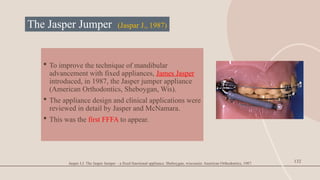
The Jasper Jumper(Jaspar J., 1987)
To improve the technique of mandibular
advancement with fixed appliances, James Jasper
introduced, in 1987, the Jasper jumper appliance
(American Orthodontics, Sheboygan, Wis).
The appliance design and clinical applications were
reviewed in detail by Jasper and McNamara.
This was the first FFFA to appear.
132
Jasper J.J. The Jasper Jumper – a fixed functional appliance. Sheboygan, wisconsin: American Orthodontics, 1987.
133.
133
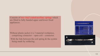
Consists of twovinyl coated auxiliary springs which
are fitted to fully banded upper and lower fixed
appliances.
Without plastic jacket it is 3 material workpiece,
comprising connector – open coil – connector.
With the link between the coil spring & the eyelets
being made by soldering.
134.
134
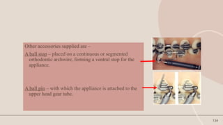
Other accessories suppliedare –
A ball stop – placed on a continuous or segmented
orthodontic archwire, forming a ventral stop for the
appliance.
A ball pin – with which the appliance is attached to the
upper head gear tube.
135.
135
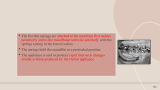
The flexiblesprings are attached to the maxillary first molars
posteriorly and to the mandibular archwire anteriorly with the
springs resting in the buccal sulcus.
The springs hold the mandible in a protruded position.
The appliance is said to produce rapid inter-arch changes
similar to those produced by the Herbst appliance.
136.
136
• Copeet al.(1994) quantified the action of the Jasper Jumper showing that the
majority of the action was due to dental, rather than skeletal change, although
the maxilla underwent significant posterior displacement and the mandible
clockwise rotation.
• Weiland and Bantleon studied consecutive growing
• patients with Class II, division 1 malocclusions treated with Jasper Jumper
appliances and reported that the correction of the malocclusion was achieved
both by skeletal (40%) and dental (60%) changes.
137.
137
ClinicalManagement
• Divided into3 phases as advocated by Dr. Jasper
• Leveling and anchorage preparation
• Period of jasper jumper use (6-9 months)
• Period of finishing (12 months)
138.
138
Alignment
• Alignment ofthe maxillary and mandibular anterior teeth during the initial
phases of orthodontic treatment must be completed. Full-sized (or nearly
full-sized) archwires should be inserted into the brackets in both arches
before the placement of the force modules.
• The archwires should be tied or cinched back posteriorly to increase
anchorage, including second molars whenever possible.
• In addition, the clinician can place posterior tip-back bends in the
mandibular archwire to enhance anchorage.
• Anterior lingual crown torque can be placed in the arch wire. Alternatively
lower incisor brackets with 5 degrees of lingual crown torque incorporated
into the slot also can be used to prepare anchorage.
139.
139
Preparation of thearches :
• After the full sized arch wires have become passive, the mandibular arch
wire is disengaged and the brackets on the 1st and 2nd premolars are
removed bilaterally.
• Unless on triggers are used, bayonet bends are placed in the archwire
distal to the lower canine bracket, and 3 mm Lexan beads are slipped over
the ends of the arch wire and moved forward to rest against the bayonet
bends bilaterally.
140.
140
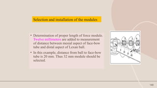
• Determination ofproper length of force module.
Twelve millimeters are added to measurement
of distance between mesial aspect of face-bow
tube and distal aspect of Lexan ball.
• In this example, distance from ball to face-bow
tube is 20 mm. Thus 32 mm module should be
selected.
Selection and installation of the modules
141.
141
• The lowerarch wire in threaded through the hole in the anterior end cap of
the force module, ligated in place and the ends of arch wire are cinched or
tied back firmly.
• Then the ball pin is inserted through the face bow tube on the maxillary first
molar band from distal to mesial and cinched forward.
• In-patients with high mandibular plane angle the pin is cinched to achieve
approximately 2mm of module deflection (150g / side).
142.
142
• In patientswith low or normal mandibular plane angle, the ball pin is
cinched forward to achieve 4 mm of module deflection (300g force/
side).
• The patients are coached to practice opening and closing movements
slowly at first and told to avoid excessive wide opening during eating
and yawning.
143.
143
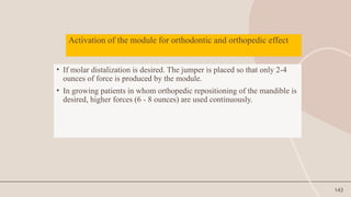
Activation of themodule for orthodontic and orthopedic effect
• If molar distalization is desired. The jumper is placed so that only 2-4
ounces of force is produced by the module.
• In growing patients in whom orthopedic repositioning of the mandible is
desired, higher forces (6 - 8 ounces) are used continuously.
144.
144
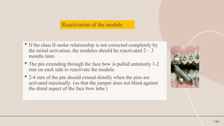
Reactivation of themodule
If the class II molar relationship is not corrected completely by
the initial activation, the modules should be reactivated 2 – 3
months later.
The pin extending through the face bow is pulled anteriorly 1-2
mm on each side to reactivate the module.
2-4 mm of the pin should extend distally when the pins are
activated maximally (so that the jumper does not blind against
the distal aspect of the face bow tube.)
145.
145
Jasper’s “theory oftwo” suggested that class II correction with
jasper jumper can be equally partitioned between 5
components –
20% due to maxillary basal restraint.
20% due to backward maxillary dentoalveolar movement.
20% due to forward mandibular dento alveolar movement.
20% due to condylar growth stimulation.
20% due to forward / downward glenoid fossa remodelling.
146.
146
INDICATIONS (Jasper andMcnamara, 1995)
• Treatment of class II malocclusions.
• Enhance anchorage for retraction of maxillary anterior teeth in class
I occlusions.
• Class III malocclusions with maxillary skeletal retrusion rather than
mandibular prognathism.
• Can be used in conjunction with rapid maxillary expansion.
147.
147
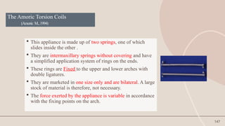
The Amoric TorsionCoils
(Amoric M.,1994)
This appliance is made up of two springs, one of which
slides inside the other .
They are intermaxillary springs without covering and have
a simplified application system of rings on the ends.
These rings are Fixed to the upper and lower arches with
double ligatures.
They are marketed in one size only and are bilateral. A large
stock of material is therefore, not necessary.
The force exerted by the appliance is variable in accordance
with the fixing points on the arch.
148.
148
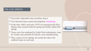
THE SAIF SPRING
(Severable Adjustable inter maxillary force)
First interarch force system developed by Armstrong
In the later 1960’s and early 1970’s he introduced the Pace
Spring, later termed multicoil spring and finally called Saif
spring.
These were first marketed by North West orthodontics, later
by Unitek, and currently by Pacific coast manufacturing.
They consist of two springs one inside the other with
soldered loops on each end.
149.
149
Various attachmentscan be placed through these loops to secure the
springs to deliver either class II or class III force.
They are available in 7 mm and 10 mm lengths, have an outside diameter
of 3 mm, and deliver 200 to 400 gms of force.
Breakage is a constant problem.
Bit bulky, not very hygienic and there is some limitation to mandibular
opening
However large forces are generated by these springs which may account
for the surprisingly rapid correction observed.
150.
150
THE KLAPPER SUPERSPRING
LEWIS KLAPPER, 1999
• This is a flexible spring element which is attached between
the maxillary molar and the mandibular canine .
• The length of the element causes it to rest in the vestibule
when activated.
• This facilitates hygiene and avoids oclusal surfaces.
151.
151
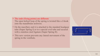
• The ends(fixing points) are different:
The open helical loop of the spring is twisted like a J-hook
onto the mandibular archwire.
• On the maxillary end it is attached to the standard headgear
tube (Super Spring I) or to a special oval tube and secured
with a stainless steel ligature (Super Spring II).
• This new version prevents any lateral movement of the
spring in the vestibule.
152.
152
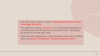
• The effectof the spring is to place a distalizing and intrusive force
tothe upper first molar.
• The appliance comes in two sizes, a 27-mmprimarily designed for
extraction cases and 40-mm for non-extraction cases. The springs
are paired for left and right sides.
• The horizontal configuration of the attachment wire at the maxillary
molar tube permits distalization with good radicular control.
153.
153
THE CHURRO JUMPER
•Introduced by Ridhardo Castanon, Mario S Valdes
and Larry White.
• This is an inexpensive alternative force system for
the anteroposterior correction of Class II and Class
III malocclusions.
154.
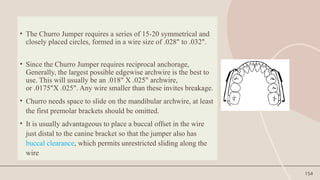
154
• The ChurroJumper requires a series of 15-20 symmetrical and
closely placed circles, formed in a wire size of .028" to .032".
• Since the Churro Jumper requires reciprocal anchorage,
Generally, the largest possible edgewise archwire is the best to
use. This will usually be an .018" X .025" archwire,
or .0175"X .025". Any wire smaller than these invites breakage.
• Churro needs space to slide on the mandibular archwire, at least
the first premolar brackets should be omitted.
• It is usually advantageous to place a buccal offset in the wire
just distal to the canine bracket so that the jumper also has
buccal clearance, which permits unrestricted sliding along the
wire
156
Hybrid functional appliances
Hybrid functional appliances are specifically and individually designed to exploit
the natural processes of growth and development.
It determines the selection of the component and their assemblies, resulting in
appliance design that matches the needs of individual patient.
Represent the combination of a rigid fixed functional appliance (RFFA) with
flexible fixed functional appliance (FFFA).
They could be described as rigid appliances with coilspring-type systems.
157.
Hybrid fixed functionalappliance
Eureka spring
Calibrated force module
Twin force bite corrector
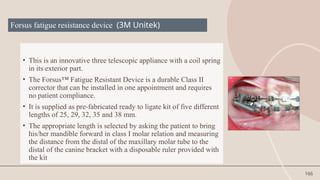
Forsus fatigue resistant device
Inverted forsus
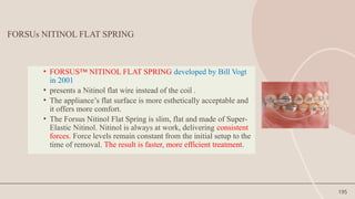
Forsus nitinol flat spring
Alpern class II closers
Powerscope
Advansync 2
157
158.
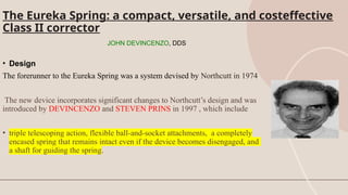
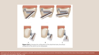
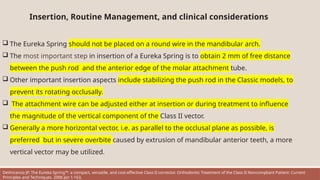
The Eureka Spring:a compact, versatile, and costeffective
Class II corrector
JOHN DEVINCENZO, DDS
• Design
The forerunner to the Eureka Spring was a system devised by Northcutt in 1974.
The new device incorporates significant changes to Northcutt’s design and was
introduced by DEVINCENZO and STEVEN PRINS in 1997 , which include
• triple telescoping action, flexible ball-and-socket attachments, a completely
encased spring that remains intact even if the device becomes disengaged, and
a shaft for guiding the spring.
159.
COMPONENTS
1. The maincomponent of the Eureka Spring is an open-wound coil spring encased in a plunger
assembly
2. The ram is made from a special work-hardened stainless steel that has been precision-machined with
three different radii.
3. At the attachment end, the ram has either a closed or an open ring clamp that attaches directly to the
archwire
4. The plunger has a tolerance of .002" within the cylinder. A triple telescoping action permits the
mouth to open as wide as 60mm before the plunger becomes disengaged . If this occurs, the system can
easily be reassembled by the patient.
5. The cylinder assembly is connected to a molar tube with an .032" wire that has been annealed at the
anterior end.
6. An .036" solid ball at the posterior end acts as a universal joint, permitting lateral and vertical
movements of the cylinder.
.
DeVincenzo JP. The Eureka Spring™: a compact, versatile, and cost-effective Class II corrector. Orthodontic Treatment of the Class II Noncompliant Patient: Current
Principles and Techniques. 2006 Jan 1:163.
160.
Eureka Spring components.A. With mouth closed in complete Class II relationship. B. With mouth open 50mm. C. Plunger
assembly extended. D. Plunger compressed to within 1mm of full compression. E. Spring-driven ram portion of plunger
assembly. F. Ring-clamp attachment of plunger assembly to archwire. G. Cylinder assembly. H. Molarattachment wire. I.
Elastomeric module stabilizing molar attachment wire. J. Ball joint at end of cylinder. K. Ligature wire stabilizing ram. L. Ram
elbow. M. Ram neck. N. Remaining distance plunger can travel before disengagement
DeVincenzo JP. The Eureka Spring™: a compact, versatile, and cost-effective Class II corrector. Orthodontic Treatment of the Class II Noncompliant Patient: Current
161.
The spring module(A) slides within a molar attachment tube (B).
A compression spring is encased within the spring module and drives the push rod (C)
against the mandibular anterior teeth.
It is important at insertion that the free distance (D), the distance from the elbow of the
push rod to the open end of the molar attachment tube, be at least 2 mm when the
mouth is closed.
DeVincenzo JP. The Eureka Spring™: a compact, versatile, and cost-effective Class II corrector. Orthodontic Treatment of the Class II Noncompliant Patient: Current
Principles and Techniques. 2006 Jan 1:163.
162.
Adjustments in theattachment wire permit alterations in the vertical component of the force vector.
Bending the attachment wire as in (A) will produce the largest intrusive component, whereas
bending as in (C) will produce the least intrusive component. (Avoid bending the attachment wire
completely vertical, because the hinge motion of the ball on opening may be limited.)
The ability to manipulate the force vector can be invaluable in obtaining rapid orthodontic treatment
and is often overlooked. For example, in an anterior deep bite a vector producing more vertical
intrusion as in (A) . should be generated, whereas where no anterior overbite is present the clinician
would be wise to create a vector nearly parallel to the occlusal plane, as depicted in (C).
In the transverse dimension, if no transpalatal arch is used, greater buccal crown torque will occur in
attachment method (A) than in (C
DeVincenzo JP. The Eureka Spring™: a compact, versatile, and cost-effective Class II corrector. Orthodontic Treatment of the Class II Noncompliant Patient: Current
Principles and Techniques. 2006 Jan 1:163.
163.
DeVincenzo JP. TheEureka Spring™: a compact, versatile, and cost-effective Class II corrector. Orthodontic Treatment of the Class II Noncompliant Patient: Current
Principles and Techniques. 2006 Jan 1:163.
164.
Insertion, Routine Management,and clinical considerations
The Eureka Spring should not be placed on a round wire in the mandibular arch.
The most important step in insertion of a Eureka Spring is to obtain 2 mm of free distance
between the push rod and the anterior edge of the molar attachment tube.
Other important insertion aspects include stabilizing the push rod in the Classic models, to
prevent its rotating occlusally.
The attachment wire can be adjusted either at insertion or during treatment to influence
the magnitude of the vertical component of the Class II vector.
Generally a more horizontal vector, i.e. as parallel to the occlusal plane as possible, is
preferred but in severe overbite caused by extrusion of mandibular anterior teeth, a more
vertical vector may be utilized.
DeVincenzo JP. The Eureka Spring™: a compact, versatile, and cost-effective Class II corrector. Orthodontic Treatment of the Class II Noncompliant Patient: Current
Principles and Techniques. 2006 Jan 1:163.
165.
• The EurekaSpring can be a valuable auxiliary in the correction of Class II sagittal
conditions.
• Its compact size permits it to be used in most patients.
• Its versatility for use in both the Class II and Class III modes when coupled with Class I
force extends the treatment planning options available for Class II corrections.
• When coupled with titanium bony anchors, very selective movement can be obtained
and
• By altering the direction of the vector, more or less intrusion can accompany the
sagittal correction.
• Light and heavy spring modules are available along with three archwire attachment
mechanisms, providing the clinician with a great variety of interchangeable options
either in treatment planning or as may arise during the
active phase.
166.
166
Forsus fatigue resistancedevice (3M Unitek)
• This is an innovative three telescopic appliance with a coil spring
in its exterior part.
• The Forsus™ Fatigue Resistant Device is a durable Class II
corrector that can be installed in one appointment and requires
no patient compliance.
• It is supplied as pre-fabricated ready to ligate kit of five different
lengths of 25, 29, 32, 35 and 38 mm.
• The appropriate length is selected by asking the patient to bring
his/her mandible forward in class I molar relation and measuring
the distance from the distal of the maxillary molar tube to the
distal of the canine bracket with a disposable ruler provided with
the kit
167.
The Forsus applianceis another of the fixed Class II correctors.
It is a hybrid type and passive appliance that means It has
moderate bulk but is flexible and adjustable as it causes the
mandible to be positioned forward.
The appliance can be assembled intraorally by attaching it to the
headgear tube and heavy archwires.
It is adjusted by adding shims to one or both sides for more
mandibular advancement. Clearly, and similar to other fixed
correctors, there are upper distal and intrusive and lower mesial
dental movements
Vogt W. The Forsus fatigue resistant device. Journal of clinical orthodontics: JCO. 2006
168.
ADVANTAGES OF FORSUS
APPLIANCE
EasyInstallation
The Forsus appliance eliminates time-consuming laboratory setup. It is
designed to be an easy chairside installation in one appointment. It does
not require removal of the bracket or archwire for placement.
Patient-Compliance
Patient compliance is minimized with Forsus correctors. The fixed appliance
does not require the patient to remove, install or adjust the device during
treatment in order for it to work properly.
Vogt W. The Forsus fatigue resistant device. Journal of clinical orthodontics: JCO. 2006 Jun;40(6):368-58.
169.
Consistent Forces
Forsus™ ClassII Correctors maintain a consistent level of force throughout treatment.
Correct activation of the module exerts approximately 200 grams of force. Forsus
Correctors consistently apply light force as compared to intermittently applied forces,
such as that offered by facebows.
Vogt W. The Forsus fatigue resistant device. Journal of clinical orthodontics: JCO. 2006
170.
Durable
Fatigue resistance isessential to successful orthodontic outcomes. The Forsus Fatigue Resistant
Device is designed to perform reliably throughout the course of treatment.
The unique coaxial spring design addresses the issue of fatigue failure. .
Prior to cycling, both the Forsus device and a competitive telescoping spring had very similar load-
deflection curves. However, after the cycle test, as the chart indicates telescoping spring shows
marked force degradation while the Forsus device maintained its consistent force delivery profile .
Vogt W. The Forsus fatigue resistant device. Journal of clinical orthodontics: JCO. 2006
171.
Patient-Friendly
The compact sizeof the Forsus corrector helps the patient feel less discomfort. Due to the spring
and
telescoping cylinder design, it does not bow outward when compressed. This linear motion of the
spring
minimizes discomfort and assists with durability.
Hygiene
The open coil spring assembly design aids in hygiene and allows food to be brushed out of the
device easily, minimizing food traps.
Predictable
The long-lasting and consistent forces along with the compliance-free design of the Forsus device
allow for more accurate predictions in treatment time and outcome.
Vogt W. The Forsus fatigue resistant device. Journal of clinical orthodontics: JCO. 2006 Jun;40(6):368-58.
172.
How Does theForsus™ Fatigue Resistant Device Work?
The Forsus device is attached to the maxillary molar
headgear tube and mandibular archwire, creating
a mesial force on the mandibular arch and a distal
force on the maxillary arch.
The intrusive force on maxillary molars can
decrease posterior vertical dimension. The intrusive
force can intrude mandibular incisors.
Vogt W. The Forsus fatigue resistant device. Journal of clinical orthodontics: JCO. 2006 Jun;40(6):368-
173.
Components
1.Spring Modules
• L-pinSpring Module
The L-pin module allows for more flexible
installation options and movement in the mouth.
It can be used with a gingival or occlusal headgear
tube. The left and right sides are universal.
• EZ2 Module
The EZ2 module allows for more consistent
installation and automatically prevents the spring
from pivoting toward the cheek. The EZ2 module
can be used only with an occlusal headgear tube
and has permanently marked indicators for the left
and right sides.
EZ2 Module. L-pin Module.
Vogt W. The Forsus fatigue resistant device. Journal of clinical orthodontics: JCO. 2006 Jun;40(6):368-
174.
2.Push Rods
The pushrods come in six different lengths and are
oriented to the patient’s right and left.
3.Measurement Gauge
The measurement gauge is used to select the
correct push rod length.
4.Headgear Tube on Band
A band and an occlusal or gingival headgear tube
(that fits .045 or .051 inch headgear) are needed to
use the Forsus™ Fatigue Resistant Device.
For the Forsus EZ2 Module, an occlusal headgear
tube measuring 3.6 - 4.3 mm is required. The L-pin
module can be used with either occlusal or gingival
tubes of varying lengths.
22 mm
25 mm
29 mm
32 mm
35 mm
38 mm
Vogt W. The Forsus fatigue resistant device. Journal of clinical orthodontics: JCO. 2006
175.
5.Rectangular Archwires
A minimumof 0.017 × 0.025 Stainless Steel
archwire is recommended for 0.018 slot in the
maxillary and mandibular arches.
A minimum of 0.019 × 0.025 Stainless Steel
archwire is recommended for 0.022 slot in the
maxillary and mandibular arches.
Vogt W. The Forsus fatigue resistant device. Journal of clinical orthodontics: JCO. 2006
176.
6.Split Crimps
Split crimpsare used to reactivate the spring
module as treatment progresses. The
recommendation is to add one split crimp (1.5 mm
of activation) to the push rod, and if another crimp
is needed, move to the next size push rod.
7.Elastomeric Ligature with Guard
The guard will act as a cushion for the sliding push
rod to contact, potentially reducing bracket failure.
Vogt W. The Forsus fatigue resistant device. Journal of clinical orthodontics: JCO. 2006
177.
Installation
The Forsus™ FatigueResistant Device is designed to be an “out of the box” appliance for easy chairside
installation, without removing the bracket or archwire. It is important to install the device at the proper time in
treatment after completing the following steps:
• Align the mandibular arch to the point that a rectangular archwire can be placed.
• maxillary transverse width must be great enough to accommodate an advanced mandibular position (relative
maxillary transverse deficiency). If necessary, coordinate the transverse dimension of the maxillary and
mandibular arch.
Once these steps are complete, the Forsus Fatigue Resistant Device can be installed.
Vogt W. The Forsus fatigue resistant device. Journal of clinical orthodontics: JCO. 2006
178.
• Bicuspid
Placing thepush rod distal to the bicuspid is a more recent recommendation for placement.The
benefits of placing the push rod distal to the bicuspid include improved patient comfort, better
aesthetics and reduced interference.
Clinical Tip
Because of the increased vertical angle, a lower first bicuspid installation can lead to more upper 1st
molar intrusion and should be monitored for
this possibility.
Determining Push Rod Position
There are three options available to place the push rods
Vogt W. The Forsus fatigue resistant device. Journal of clinical orthodontics: JCO. 2006
179.
• Cuspid
The traditionallocation to place the push rod is distal to the cuspid. Placement behind the cuspid will
work in most cases, especially when the bicuspid is not an option, for example:
• When placement at first bicuspids is over-active
with a 22 mm push rod
• When placement is more vertical than needed
• Severe Class II malocclusions where a large portion of the discrepancy is from a retruded
mandible
• Omega Loop
Using an Omega Loop allows the angulation tobe varied. It will also keep the push rod from contacting the
bracket.
Clinical Tip
Because of the increased vertical angle, an Omega Loop installation can lead to more upper 1st
molar intrusion and should be monitored for this possibility.
Vogt W. The Forsus fatigue resistant device. Journal of clinical orthodontics: JCO. 2006
180.
Preparing the Archfor Installation
1. Install rectangular archwires (minimum of 0.017 × 0.025 Stainless Steel in 0.018 slot, minimum of
0.019 × 0.025 Stainless Steel in 0.022 slot).
2. To secure mandibular arch teeth positioning and prevent lower anterior flaring, please consider
the
following options:
• Make sure lower anterior brackets have adequate negative torque or consider Variable Prescription
Orthodontics (VPO).
• Cinch back mandibular archwire distal to terminal molar, tying arch together as a unit.
• Lace the entire mandibular arch from first molar to first molar under the archwire. This can also
reduce the occurrence of ligature breakage from the friction of the push rod.
Vogt W. The Forsus fatigue resistant device. Journal of clinical orthodontics: JCO. 2006
181.
3. To preventrotation and debonding:
• Steel ligate lower bracket mesial to push rod placement (cuspid or bicuspid).
• Install a stop, such as a Gurin lock, distal to the bracket where the push rod will be placed, to avoid
contact with the bracket.
• Place elastomeric ligature with guard under the archwire on the bracket of the tooth mesial to the
push
rod to prevent contact; the pad should face distally. This will add 1.5 – 2 mm of activation to the push
rod.
Vogt W. The Forsus fatigue resistant device. Journal of clinical orthodontics: JCO. 2006
182.
Installing the Forsus™Fatigue Resistant Device
Push Rod Selection
1. Use the Measurement Guide to determine correct push rod length, depending on the selected push rod
location (distal to cuspid, bicuspid, Omega loop).
a. Measure each side from the distal end of maxillary molar tube to the distal side of the chosen mandibular
stop, having the patient bite in centric occlusion without advancing the mandible. When in doubt, use the
shorter length push rod.
b. Select the Right and Left configuration push rods from the available sizes.
NOTE: It is important to measure both the right and the left sides.
2. Once the correct push rod size is selected, install either the EZ2 or L-pin spring module.
Vogt W. The Forsus fatigue resistant device. Journal of clinical orthodontics: JCO. 2006
183.
EZ2 ModuleInstallation
1. Clear headgear tube to ensure there is no blockage from debris.
2. Holding the mesial portion of the Forsus™ Fatigue Resistant Device EZ2 Module with Weingart utility pliers,
insert the clip into the headgear tube from mesial to distal until it clicks into place. (NOTE: Right and Left
configuration denoted by “R” or “L” on each module.)
3. Lightly tug on the clip to ensure the clip is properly engaged.
Vogt W. The Forsus fatigue resistant device. Journal of clinical orthodontics: JCO. 2006
184.
L-pin Installation
1.Clear headgear tube to ensure there is no blockage from debris.
2. Insert L-pin into spring module, making sure the ball is positioned buccally.
3. Insert L-pin into headgear tube from distal tomesial. Allow 1 to 2 mm of clearance between distal end of
buccal tube and the universal spring eyelet.
4. Bend L-pin occlusally or gingivally.
• If bending the L-pin occlusally, flip the spring module toward the gingival, bend the L-pin to the occlusal and
then let the spring fall into position.
• If bending the L-pin gingivally, bend the L-pin over the gingival tube. The L-pin can also be secured behind the
elastic hook.
Vogt W. The Forsus fatigue resistant device. Journal of clinical orthodontics: JCO. 2006
185.
Push Rod Placement
1.Select appropriate side (right or left) push rod
2. Place the push rod loop over the archwire distal to the selected position (first bicuspid or cuspid).
3. Have the patient open his/her mouth, compress the spring, and insert the push rod into the
spring.
4. Once the push rod is placed in the correct position, have the patient bite down in centric occlusion
and double check the spring activation.
• Correct activation exerts approximately 200 grams of force.
• There should be 2 mm of space (1 mm minimum) between the completely compressed spring and
the stop on the push rod, with patient in centric occlusion.
5. Crimp the mesial end of the push rod with Weingart pliers to close the loop around the archwire.
6. Check for any interference with the spring module, push rod, or brackets.
• Have patient bite down and open and repeat.
• Have patient slide mandible from side to side.
Vogt W. The Forsus fatigue resistant device. Journal of clinical orthodontics: JCO. 2006
186.
Place push roddistal to selected position Crimp push rod.
Vogt W. The Forsus fatigue resistant device. Journal of clinical orthodontics: JCO. 2006
187.
Avoiding Overactivation
It isimportant to avoid overactivation. If the push rod protrudes distally of the spring module in centric
occlusion, the spring is overactivated because the push rod is too long. Overactivation can result in:
• Debonding of brackets
• Unwanted dental movements
• Flaring of mandibular incisors
• Unplanned rotations
• Breakage
Note: If the push rod is overactivated, switch to a shorter push rod.
Correct
Activation
Overactivation
Overactivation causes the spring to
look fully compressed
Correct
Activation
Overactivation results in
tube being pushed
beyond the end
of the spring.
Vogt W. The Forsus fatigue resistant device. Journal of clinical orthodontics: JCO. 2006
188.
Reactivating the Forsus™Fatigue Resistant Device
As treatment progresses, reactivation of the spring may be necessary to reach the desired Class I
relationship.
1. To check the activation, have the patient bite in centric occlusion, hold the push rod and
completely compress the spring. Activation will depend on the amount of push rod visible
between the stop and the spring.
2. Push the spring back and check to see if there is 2.5 mm of space between the push rod stop and
the end of the spring.
3. Have the patient open his/her mouth as wide as they can. If the patient can open their mouth fully
without the push rod disengaging from the spring, the Forsus push rod can be reactivated.
Option 1: Compress the spring so that the push rod is exposed and place a split crimp distal to the
stop on
the push rod.
Option 2: However, if the push rod disengages from the spring, remeasure and select the
appropriate larger size of push rod to install instead of using a split crimp.
Vogt W. The Forsus fatigue resistant device. Journal of clinical orthodontics: JCO. 2006
189.
4. Cinch thecrimp onto the push rod. This will provide 1.5 mm of activation.
Clinical Tips
1. If greater than the 1.5 mm of activation provided by one crimp is required, replace the push rod with a
longer push rod.
2. Reactivation may only be achieved on push rods sizes that have stops. Since the 22 mm push rod does not
have a stop, use the 22 mm push rod to do initial advancement, and then replace it with a 25 mm push rod
when there is adequate space.
3. Usually one split crimp per appointment will be needed, exclusions include non-growing patients.
4. The Forsus device can be activated unilaterally, which helps with midline control.
5. When additional activation is needed, repositioning the push rod from the cuspid to first bicuspid is also
an option.
Vogt W. The Forsus fatigue resistant device. Journal of clinical orthodontics: JCO. 2006
190.
Removal
The Forsus FatigueResistant Device is ready to be removed when:
• Buccal segments and molar relationships are Class I
• Maxillary incisors have ideal torque and position
• Overjet is eliminated
A recent study showed that Class II correction with the Forsus device will be achieved in 4-6
months.*
.
Vogt W. The Forsus fatigue resistant device. Journal of clinical orthodontics: JCO. 2006
191.
Removal Instructions
Once theClass II malocclusion is corrected, it is time to remove the Forsus device.
EZ2 Module:
1. With the patient’s mouth open wide, compress the spring and remove the spring assembly from the push
rod.
2. Then, holding the distal end of the Forsus EZ2 Module with a pair of Weingart pliers, pull the distal end of the
clip in an occlusal then mesial direction to remove it from the headgear tube.
L-pin Module:
1. Keep the push rod and spring module engaged;
have the patient bite together.
2. Using Weingart pliers, unbend the L-pin and
thread it through the buccal tube; the active
spring will push pin out distally.
Vogt W. The Forsus fatigue resistant device. Journal of clinical orthodontics: JCO. 2006
192.
Push Rod Removal
Oncethe spring module is removed, remove the push rod.
• First, rotate the push rod so that the bend is facing occlusally.There are
3 options to remove the push rod from the archwire.
Option 1: Using a pin and ligature cutter, place the tips between where
the end of the push rod is cinched and squeeze to separate.
Option 2: Grasp the distal end of the push rod with your fingers, holding
the mesial loop with the Weingart pliers. Twist the loop open, away from
the straight push rod, and rotate the push rod from the archwire.
Option 3: If an archwire change is planned at the current point in
treatment, remove the push rod along withthe current archwire.
Vogt W. The Forsus fatigue resistant device. Journal of clinical orthodontics: JCO. 2006
193.
What to Lookfor at Each Appointment
It is important to keep all scheduled appointments to monitor progress. At each appointment, you
will want to check how the appliance is performing.
1. Check activation in centric occlusion in 6-8 week intervals.
a. If the spring module compresses more than 2.5 mm above the stop on the push rod and
additional
correction is required, reactivate the appliance.
b. Typical reactivation is a single split crimp placed on the push rod above the stop (except for the 22
mm
push rod).
c. Forsus Correctors may be activated unilaterally.
d. After the first reactivation, replacement of the push rod with a larger size may be indicated.
Vogt W. The Forsus fatigue resistant device. Journal of clinical orthodontics: JCO. 2006
194.
2. Evaluate maxillaryincisor torque. Ideal torque needs to be maintained to avoid overretraction of
the
maxillary dentition.
3. Evaluate mandibular incisor proclination. Excessive proclination will result in the elimination of
the overjet while the buccal segments are still Class II.
4. If the maxillary archwire has not been cinched distal to the molar, ensure the maxillary wire
length is
adequate to avoid the tube backing off the end of the wire.
5. Check that the spring modules are not interfering with the occlusion.
6. Check wire engagement in all brackets and check that the steel ties on cuspids or first bicuspids,
dependent upon push rod placement, are secure.
7. Once the desired amount of correction is achieved, it is recommended to keep the non-activated
appliance in place for at least one appointment interval. "Non-activated" means that the Forsus
Corrector spring module is not compressed by the push rod as the patient bites down
Vogt W. The Forsus fatigue resistant device. Journal of clinical orthodontics: JCO. 2006
195.
195
FORSUs NITINOL FLATSPRING
• FORSUS™ NITINOL FLAT SPRING developed by Bill Vogt
in 2001
• presents a Nitinol flat wire instead of the coil .
• The appliance’s flat surface is more esthetically acceptable and
it offers more comfort.
• The Forsus Nitinol Flat Spring is slim, flat and made of Super-
Elastic Nitinol. Nitinol is always at work, delivering consistent
forces. Force levels remain constant from the initial setup to the
time of removal. The result is faster, more efficient treatment.
196.
196
THE TWIN FORCEBITE CORRECTOR
• The TFBC is a fixed, push-type intermaxillary functional appliance with ball-and-socket
joint fasteners that allow a wide range of motion and lateral jaw movement.
• The two plunger/tube telescopic assemblies on each side contain nickel titanium coil
springs that deliver a constant force of approximately 210g.
Chhibber, A., Upadhyay, M., Uribe, F., & Nanda, R. (2013). Mechanism of Class II correction in prepubertal and postpubertal patients
with Twin Force Bite Corrector. Angle Orthodontist, 83(4), 718–727
197.
197
The TWINFORCE Bite Corrector will fit either the
right or left sides and may be used for both Class II and
Class III correction.
Two sizes are available for non-extraction and mixed
dentition cases as well as extraction cases.
Ball joints provide lateral flexibility and full
mandibular movement.
198.
198
Changes produced byTFBC
• Mainly dentoalveolar changes
• NO significant improvement in mandibular length and position
• Restriction of maxillary growth (headgear effect)
• Proclination of lower incisors
• Mesial movement of lower molars
• Distal movement of upper molar
• No deleterious effect on TMF was noted
• Redirection of mandibular growth (not significant)
Chhibber, A., Upadhyay, M., Uribe, F., & Nanda, R. (2013). Mechanism of Class II correction in prepubertal and postpubertal patients with Twin
Force Bite Corrector. Angle Orthodontist, 83(4), 718–727
199.
199
ALPERNCLASSIICLOSERS
• Predominantly appliedin Class II correction and as a substitute
for elastics.
• It consists of a small telescopic appliance with an interior coil
spring and two hooks for fixing
• It functions in the same way as elastics and, similarly, is fixed
to the lower molar and to the upper cuspid.
• It is available in three different sizes.
• Its telescopic action enables a comfortable opening of the
mouth.
200.
200
POWER SCOPE
• Dr.Andy Hayes worked in conjunction with
American Orthodontics to develop PowerScope
One-size - fits all Class II cases
• This wire-to-wire device delivers unmatched patient comfort,
eliminates the need for headgear tubes or special band
assemblies, and can be used with either banded or bonded
molar tubes.
Dhiman I, Dhiman P. Power scope non-compliance Class II corrector. A review. International journal of current
research. 2017 Jul;9(7):54157-62.
201.
201
• 18 mmTELESCOPING MECHANISM
• Nickel titanium internal spring mechanism
• Low profile means a more aesthetic appearance, and its smooth, rounded design
provides better patient comfort. There’s no piston extending distally from the upper
molars, which helps reduce ulceration.
204
Advance sync 2
•AdvanSync was developed by Terry and Bill Dischinger in 2008 in
conjunction with Ormco for treating skeletal class II malocclusion.
• It is a fixed tooth-born functional appliance consisting of crowns cemented on
maxillary and mandibular permanent first molars, a position where orthopedic
forces are applied.
• The appliance was designed to advance the mandible to class I occlusion
within 6–9 months, while allowing simultaneous use of fixed orthodontic
appliances.
• The appliance is almost half the size of the MiniScope Herbst appliance that
has been in use.Because of the smaller size, it fits more comfortably in the
posterior of the mouth.
205.
205
Indications
• It isdesigned to advance the mandible to class I occlusion
within six to nine months while patient has been bonded
upper and lower 2nd premolar to 2nd premolar.
• It provides maximum comfort and range of movement and
reduces the necessity for patient compliance.
• It is placed with first bonding synchroning class ii
treatment with orthodontic therapy.
• Provide constant activation.
Dischinger BM, “Skeletal class II case presentation: utilization of the Advansync2 appliance”, Asia Pacific Orthodontic Society
Trends in Orthodontics, Sept. 2018, Vol.8, Issue 3 , pp. 168–174.
206.
206
Advantages
• The toothmovement mesial to the 1st molar can be carried out
simultaneously, thus eliminating the need of two-phase treatment.
• Step-wise advancement of the appliance brings better skeletal effect.
• AdvanSync2 is not attached directly on the wire and also the telescopes are
shorter, thus they do not exert more horizontal vector of force leading to
lower incisor proclination.
207.
207
Disadvantages
• There isposterior open-bite observed in pre-molars and the
molar segment when the appliance is removed.
• However, this is correctable either by:
a) Gingival re-positioning of the brackets
b) Banding of 2nd molars
c) Settling elastics
• De-cementation of the appliance
• Un-screwing of the appliance
208.
(0.0220 ×0.0280 )slotedgewise bracket system is fully bonded with the brackets on the mandibular
incisors having a built-in labial root torque.
This functional appliance includes stainless-steel crowns with single archwire tubes on permanent first
molars. The AdvanSync did not include lower lingual holding arches, and the maxillary and mandibular
crowns of this appliance are connected by telescopic rods
The telescopic mechanism acts to constantly posture the mandible forward upon closure, with the goal of
enhancing mandibular growth
The appliances are activated 2 to 4 mm every 3 months for 6 to 12-month duration until moderate dental
overcorrection is achieved.
Over-correction is desirable to counteract some relapse of mandibular anterior repositioning
Mechanism
Dischinger BM, “Skeletal class II case presentation: utilization of the Advansync2 appliance”, Asia Pacific Orthodontic Society Trends in
Orthodontics, Sept. 2018, Vol.8, Issue 3 , pp. 168–174.
209.
209
CONCLUSION
Successful treatmentalways begins with good diagnosis for which an
appropriate treatment plan is formulated .
This is followed by mechanotherapy in order to attain the desired treatment
objectives.
Early Orthodontic treatment can be very rewarding if the changes associated
with facial growth and development and patient response are anticipating
correctly, with a sound problem list and treatment goals.
210.
210
Fixed functional appliancesform an useful addition to the clinician’s
orthodontic armamentarium.
But many of these appliances need further studies to substantiate the claims
made by their respective originators.
With this in mind, clinicians must take great care in selecting the right patient
and also pay attention to every detail in the manipulation, to attain successful
results with these appliances.
211.
211
REFERENCES
Thomas M.Graber,Thomas Rakosi, Alexander G.Petrovic.Dentofacial Orthopedics with Functional Appliances
Graber, Vanarsdall, Vig.Orthodontics- Current Principles and Techniques. 6th
edition
Profitt W.R.: Contemporary Orthodontics ; 6th
edition
Om Prakash Karabanda.Orthodontics diagnosis and management of dentofacial deformities
Pancherz H. The mechanism of Class II correction in Herbst appliance treatment. Am. J. Orthod. 1982; 87: 1-20.
Pancherz H. The Herbst appliance – Its biological effects and clinical use. Am. J. Orthod. 1985; 87: 1-20.
212.
212
Kinzinger, Deidrich:Bite jumping with the functional mandibular Advancer, JCO December 2005 page
696-700
Carlos Martins Coelho Filho,Mandibular Protraction Appliances for Class II Treatment Volume 1995
May(319 - 336)
Sabine Ruf, Hans Pancherz: When is the ideal period for Herbst therapy-Early or Late? Semin Orthod
2003,March,page 47-56
Mc Namara, Brudon, Kokich, Orthodontics and Dentofacial Orthopaedics, 2001 page 285,333
213.
213
Kinzinger, Oestheimer,Deidrich: Development of a new fixed functional appliance for treatment of skeletal class II
malocclusion.J. Orofac Orthop 2002 63:384-399
Ken Hansen: Treatment and posttreatment effects of the herbst appliance on the dental arches and arch relationships. Semin
Orthod 2003 March,page 67-73
Larry.W. White :Current Herbst Appliance Therapy:JCO 1997,May(296 - 309)
Miller R.A. The Flip-lock Herbst Appliance. J. Clin. Orthod. 1996; 30: 552 – 58.
Jasper J.J., McNamara J. The correction of interarch malocclusions using a fixed force module. Am. J. Orthod. Dentofac. Orthop.
1995; 108: 641-50.
Pancherz H. Treatment of Class II malocclusions by jumping the bite with the Herbst appliance. A cephalometric investigation.
Am. J. Orthod. 1979; 76: 423-442
Editor's Notes
#16 Mandibular in cisor proclination is the most pronounced dentoalve olar side effect seen during fixed functional treat ment.4,8,27–31 This is a matter of concern in patients, as it increases relapse tendency and also limits skeletal and soft tissue correction.4,27–31 This could be prevent ed by cinching the mandibular archwire and laceback in the mandibular arch and by incorporating progres sive lingual crown torque in the mandibular anterior segment
#25 Hagg & Tarangerin 1982
. MP3-Fstage (onset or start of the curve of pubertal growth spurt); In this stage epiphysis is as wide as metaphysis. 2. MP3-FG stage (acceleration part of the curve of pubertal growth spurt); Epiphysis is as wide as the metaphysis and there is a distinct medial and or lateral border of the epiphysis forming a line of demarcation at right angle to the distal border. 3. MP3-G stage (peak-PTV, the point of maximum pubertal growth spurt); Sides of the epiphysis becomes thick and caps its metaphysis forming a sharp edge distally at one or both sides. 4. MP3-H stage (deceleration part of the curve of pubertal growth spurt); Fusion of the epiphysis and metaphysis begins. 5. MP3-I stage (end of pubertal growth spurt); Fusion of epiphysis and metaphysis is completed Chapman in 1972 was the first to use periapical x-ray film to evaluate ossification of 10 the ulnar sesamoidbone as a skeletal maturity indicator
#27 Dentoalveolar changes- proclination of lower incisors
retroclination of upper incisors
differential eruption of teeth
mesial nd vertical eruption of lower molars
changes in functional occlusal plane
#65 MP3- F : start of curve of pubertal growth . Epiphysis wide as metaphysis
MP3-G : Maximum point of pubertal growth spurt
#66 Stage R-I: fusion of epiphysis and metaphysis has begun. Stage R-IJ: fusion is almost completed, but there is a small gap at one or both margins. Stage Rz]: fnsion of epiphysis and metaphysis is completed.
#78 As the bicuspids are driven down, the effective length of the plunger-sleeve combination (which advances the mandible) shortens, so that the mandible is held less far forward. Compensation for this deactivation requires lengthening the upper sleeves, either by placement of shims between the paired telescoping elements, or by replacement of the upper sleeves.
#81 The maxillary splint covers all the maxillary teeth except the incisors and the acrylic coverage extends from the free gingival margin of the buccal surfaces over the occlusal ending to the free gingival margin on the lingual surfaces.64 A transpalatal arch or, more usually, a rapid palatal expansion screw attached to the wire framework connects the left and right parts of the splint together. Regarding the mandibular splint, the incisal one third of the mandibular canine and incisor crowns is covered with acrylic, which can reduce incisor proclination, the posterior teeth are fully covered, while occlusal rests are placed on the second molars when erupted.43,64 To facilitate removal of the appliance, Howe recommended the maintenance of openings over the cusps of the posterior teeth in both upper and lower splints.
#82 In addition, a plate was constructed in the upper jaw as anchorage for a headgear to be worn 12 to 14 hours per day. A combination of high-pull and low-pull forces was used. Forces of 1,500 to 2,000 gm on each side were used during active treatment in the first ten cases.
#108 During opening of the mouth, the upper loop moved mesially along the maxillary archwire while the lower moved distally along the mandibular archwire. During mouth closing, each loop moved in the opposite direction (Fig. 7.1A). However, this model interfered with mouth opening, causing too many breakages of archwires as well as loosening of bands..
#109 The author then developed a second design aimed at solving the limitation in mouth opening. It consisted of two pieces of 0.036′′ stainless steel wire, each with a circular loop at one of its tips. After slipping one piece of coil into one of the components, the tip of each component was reciprocally inserted into the circular loop belonging to the other. The piece of tubing or coil placed between them was meant to prevent too much approximation of the two circular loops belonging to each part, since this might cause undesirable movement between the parts. With this configuration, each part could slide along the other without too much instability between them. This new design was named the MPA II (Fig. 7.1B). Although it represented an improvement over the original MPA, the MPA II still suffered from instability during functioning. The author believed this was due to the way the appliance was adapted to the archwire in each jaw. He realized that stability could be attained only if the appliance could move around an axis in each jaw and not run along the archwires as it did until then
#110 This was partly achieved in the MPA III, which had a mandibular rod rotating within a circular loop placed in the lower archwire distally to the lower cuspid. The longer section of the mandibular rod ran within a telescopic tube that was introduced in this design. Stability was greatly increased in the MPA III but the author considered that it could be improved even more if the adaptation of the appliance to the upper jaw also resembled a rotation around an axis.
#114 This was achieved only in the MPA IV, in which the maxillary extremity of the appliance ran around a 1 mm sectional stainless steel wire that was bent 90° before entering the distal side of the 0.045′′ round molar tube and was locked in its mesial side (Fig. 7.1D). The MPA IV thus achieved the maximum stability possible and a neartotal absence of break
#166 The Forsus Fatigue Resistant Device (FRD) is an interarch push spring that produces about 200 g of force when fully compressed.
It was given by WILLIAM VOGT.