SlideShare a Scribd company logo
1 of 20
Download to read offline
1
DEPARTMENT OF MECHANICAL ENGINEERING
TECHNOLOGY
Faculty of Engineering and Built Environment
UNIVERSITY OF JOHANNESBURG
Doornfontein Campus
TITLE OF PROJECT
The pedal press pneumatic lifting jack
by Sambo NP Student No: 218001444
Supervisor(s): Dr S. Gqibani
Subject: PMMIA3
Date: 09 APRIL 2023
2
DECLARATION
I confirm that the work presented below is my work. Secondary sources were used to conduct
research and acknowledge and cited. I confirm that this work was never submitted.
Sambo NP 9 April 2023
Signed Date
3
Table of Contents
TITLE OF PROJECT...........................................................................................................................1
1.1INTRODUCTION AND BACKGROUND................................................................................4
1.2. LITERATURE REVIEW..........................................................................................................5
1.2.1Design and fabrication of remote-controlled system ...............................................................5
1.2.3. The Design of floor lifting jack..............................................................................................7
1.2.5 Design of a bottle hydraulic jack ............................................................................................8
1.3 .DESIGN STRATEGY ..............................................................................................................8
Modify..........................................................................................................................................8
Addition........................................................................................................................................9
2.1 PROBLEM STATEMENT........................................................................................................9
Design requirements.....................................................................................................................9
Design constrains. ......................................................................................................................10
3.FUNCTIONAL ANALYSIS ......................................................................................................10
4.CONCEPT GENENERATION ..................................................................................................11
5.FINAL DESIGN DESCRIPTION ..............................................................................................18
CONCLUSION..............................................................................................................................19
Recommendations..........................................................................................................................19
REFERENCES...............................................................................................................................20
4
1.1INTRODUCTION AND BACKGROUND
working with heavy materials could be stressful and human power input demanding. The man goes
by the name Frank L and Mr Gormley invented a first lifting jack which was hydraulic jack, Kumar
P (2019). Their aim was to transport materials optimum and lift Materials. Lifting jacks are tools
used to lift heavy machinery system to perform maintenance, Borse et al. (2020). Car lifting jacks
are the tools used to lift car in case of emergency replacement of wheels or car parts. Pneumatic
jacks are powered by compressed air and are used for lifting and positioning heavy material and
machinery effortlessly, Borse et al. (2020). Pneumatic power turns electric power into mechanical
power with the help of compressed air. The compressed air transfers the force for the purpose of
lifting, pushing, or moving of heavy components, Mechanical projects, (2022). The are three types
of operating mechanism which is mechanical system, hydraulic system and pneumatic system.
Pneumatic jack is made up of following components Pneumatic Piston Air Pump, Side
Support Rods Switching Valve, Pipes and Joints, Base Frame, Supporting Frame, Mounts and
Joints, Nuts and Bolts, Screws and Joints, Mechanical projects (2022).
5
figure1: adapted from
Walmart
advantages
• Generates large lifting forces.
• Has high efficiency
• Overall operating environment versatility
1.2. LITERATURE REVIEW
1.2.1Design and fabrication of remote-controlled system
Commented [Ns1]:
6
Figure2: a picture of remote-controlled hydraulic jack
The design of remote-controlled system was designed with an objective of modifying the hydraulic
jack lift and test the efficiency of the fabricated design. It was designed such that withstand or has a
maximum lifting capacity of 30000kg, Asonye et al (2021). It is specifically made for heavy
equipment in farms, construction industries and workshops. It is made up of the following
components: hydraulic pump, control valves, reservoir, pump, check valve, ram piston and release
valve Asonye et al (2021). Advantages of this design are reducing working load during maintenance
operations, manual power not required, increases timeliness and efficiency in maintenance
operations reduces the risk of getting injury in the case of malfunctioning of the device, Asonye et
al (2021).
1.2.2Design of scissor lifting jack
Figure 3: a picture of scissor lifting jack applied on a car
Scissor jack are common lifting jacks that are operates with mechanical mechanism to move up its
parts .in order to lift up car A scissor jack is a device constructed with a crosshatch mechanism,
much like a scissor. scissor lifting jacks are mechanical operated jacks it is operated by turning a
lead screw, Osama (2019). It is commonly used as carjacks. In the case of a scissor jack, a small
force applied in the horizontal plane is used to raise or lower large load. The scissor jacks consist
the following components of four lifting arms, a base plate, a carrier plate, two connection
members, eight connection pins, a power screw and a crank Osama (2019).
7
1.2.3. The Design of floor lifting jack
Figure 2: adopted from AJM group
The design of floor lifting jack is modified from the existing hydraulics jack. It was also indicated
that the hydraulic lifting jack are more efficient since the allowed a maximum load of 40000 N,
(Hasan,2019). The design of a floor jack was aimed to be easy operated and less labour. The
system of the floor jack allows operator rolls to roll in order the to position the saddle is
positioned aligned with the lift point. The hydraulic cylinder gives rise to the lift arm for the
saddle to contact the car base by pumping up and down on the handle, (Hasan,2019).
1.2.4 Design and construction of electric powered toggle jack
Figure 5: a picture of a toggle jack adapted from amazon.
8
The above configuration of electric powered lifting jack design as it will be explained.
The design of electric powered toggle jack was aimed to develop mechanism based on power
toggle. Jack that is more efficient, having high stress resistant, save time and reliable to achieve
lifting load, (Ipalakyelaa, et al.,2017). Power screws are used to help with bearing the load. fluid
lubrication is used to maximized efficiency, (Ipalakyela, et al.,2017). Servomotor was selected
because of its advantage of producing high torque. This design of lifting jack operates as motorized
mechanism. The components of the toggle jack design are: Upper links, Load bearing, support, the
power screw shaft, 2 pins base support, Lower links, Driven gear, Driver, Gear housing, Base
support, Servo motor, Alligator clips, Power switch and Connecting cable.
1.2.5 Design of a bottle hydraulic jack
The design of a bottle hydraulic jack was designed by, (Patel,2018) aimed to modify the existing
design of car jacks to improve its functionality and also human safety factors to be taken into
considerations. (Patel, 2018) stated that their modified design allows to lift load in any slope
position, less human energy will be used to operate and will be user friendly such that no skill is
required to operate it. This design was also made to overcome the challenges listed with the prior
designs which were listed by (Sachin, Nd), More human energy consumption, Maintenance is high,
Suitable for small capacity, not suitable for woman. The bottle jack acts as a powerhouse of the
lifting, it consists of a piston in a vertical form that support a bearing pad which touches the object
to be lifted.
1.3 .DESIGN STRATEGY
The design strategy for this project is aimed to modify a pneumatic lifting jack by modifying
and improving the existing hydraulic jack. This design will be promoting safety to the users
which will not require them to use too much effort to operate it and also will be accessible to
use for everyone. Another aim is to prevent the possible accident and injuries that are caused by
unstable lifting jacks.
Modify
• Modifying the existing hydraulic jack into pneumatic jack
• Designing a well balance structure for the jack.
9
• Improving the size of the pneumatic jack from the existing hydraulic jack such that the size
will be able to carry big loads.
Addition
• Adding pedal to apply pressure on the control valve.
• Installing a safety excess flow valve
• Clampers will be added to give strong balance.
2.1 PROBLEM STATEMENT
car drivers they come across challenges during their driving along the road which include
bursting of tyres or car wheels experience puncture, which requires them to change the wheels
or replace other parts of the car which they need to lift the car in order to perform that work.
The biggest challenge is that to order lift up the car on needs more energy to pull up and
possible injuries occurs as (Archrgbenda, et al.,2017) stated the mechanic might get accident
such as breaking of spinal cord and other body parts even possible death. Although lifting jacks
were designed and produced but they still have challenges which include unreliable balance
since they do not give enough stability to the cars (Archrgbenda, et al.,2017). Also, slipering of
the rod when is brought in contact with the lifting jack it makes the car not to be balanced.
Some designs still require a human effort and takes time to lift up the load for an example a
scissor lift the improve design of pedal pneumatic lifting jack will be designed such that it made
it possible to lift up car and provide reliable balance with a help of stabilizers.
Design requirements
• It must be able to lift up the carload.
• Provide stable balance to the car regardless of car position slope.
• Must be able to clap the car rod to prevent it from moving.
• It must be able to level and position the car to the desired position.
• it must be able to generate the lifting power through the compression of air or gas.
• it must be able to deflate its size.
10
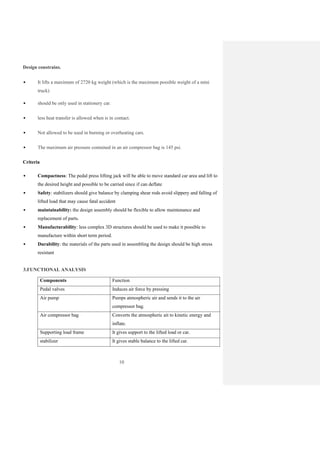
Design constrains.
• It lifts a maximum of 2720 kg weight (which is the maximum possible weight of a mini
truck)
• should be only used in stationery car.
• less heat transfer is allowed when is in contact.
• Not allowed to be used in burning or overheating cars.
• The maximum air pressure contained in an air compressor bag is 145 psi.
Criteria
• Compactness: The pedal press lifting jack will be able to move standard car area and lift to
the desired height and possible to be carried since if can deflate
• Safety: stabilizers should give balance by clamping shear rods avoid slippery and falling of
lifted load that may cause fatal accident
• maintainability: the design assembly should be flexible to allow maintenance and
replacement of parts.
• Manufacturability: less complex 3D structures should be used to make it possible to
manufacture within short term period.
• Durability: the materials of the parts used in assembling the design should be high stress
resistant
3.FUNCTIONAL ANALYSIS
Components Function
Pedal valves Induces air force by pressing
Air pump Pumps atmospheric air and sends it to the air
compressor bag.
Air compressor bag Converts the atmospheric ait to kinetic energy and
inflate.
Supporting load frame It gives support to the lifted load or car.
stabilizer It gives stable balance to the lifted car.
11
To start the lifting user must place the jack under the object to be lifted. The force is applied on the
pedals valve by stepping to the pedals that switch on the direction of lifting valve. This force drives
the air pump it therefore flows to the air compressor bag. As the pressure is applied on the valve the
air compressors fuel up the air bag compressor and causes the supporting frame to move upwards to
the desired distance and the car or load get lifted. The opposite valve is pressed in the pedals to lower
the lifted load. The air pressure is drained out from the air compressor bag which eventually deflates
and load is brought down.
4.CONCEPT GENENERATION
The concepts generation of a lifting jack will generate by investigating the different mechanism of
lifting jack by that way will make it possible analyse the existing designs and generation of new
ideas on improving. The S.C.A.M.P.E.R(Substitute. Combine. Adapt. Modify Put to other uses.
Eliminate. Rearrange or Reverse) method will be implemented to strategize on improving the
design. The best four designs are listed below.
CONCEPT1: Scissor lifting jack
A scissor lifting jack is most use jack for passenger cars because of its reliability in carrying and
supporting the weight load.it is a mechanical operated machine which consist of main . scissor jack
has a crank, structured in a form of Z shape ,The lift is operated by turning the crank that is inserted
into one end of the scissor jack. The crank shaft control the movement of the scissor lift
components. The end fits into a ring hole that is at the end of the rod, it also acts as a object force of
the scissor lifts . When this crank is turned, the rod turns, and this lifts the jack. The threaded rod
acts like a gear mechanism. It has teeth (the screw thread),they are responsible for turning and
moving the two arms in order for lifting to take place which turn and move the two arms,
12
Platform: The platform is the part of the scissor lift that holds the load. It can be raised or
lowered to the desired height using the scissor mechanism. It is made up of material that has
high strength to withstand high load since the load is direct applied to it.
Base: The base provides stability and support for the scissor lift. It is typically equipped with
wheels or casters for easy movement.
Scissor mechanism: The scissor mechanism is the heart of the scissor lift. It works by using
hydraulic cylinders or electric motors to raise and lower the platform. The mechanism consists
of a series of linked supports that move in a scissor-like motion, allowing the platform to be
raised to different heights.
Controls: The controls are used to operate the scissor lift. In this design the movement is controlled
by the screw and crank which are rotated for the platform to move up to the desired height
CONCEPT 2: Hydraulic bottle lifting jack
The hydraulic lifting jack has two (there is the bigger pistons and smaller pistons) inside the
cylinder that are responsible for lifting applied load or heavy load. The smaller piston is connected
to the bigger piston. The smaller piston exerts the force to the bigger piston and cause it to move up
cause it to lift and lift the load too. It is made up of two valves ball, which is check valve it allows
the fluid flow and stop the fluid flow. The handle socket of the jack has bar inserted to it causes the
pumped o hydraulic fluid to go through one-way valve. The fluid force acts in the bottom of the
13
bigger cylinder by allowing the ram to go upwards. The other valve remains blocked the
pressurized fluid. The functional components are listed below.
Piston: The piston is the part of the jack that moves up and down inside the cylinder. It is
responsible for creating the force that lifts the load.
Cylinder: The cylinder is the outer casing that holds the piston and hydraulic fluid. When the
piston is pushed down, it forces the hydraulic fluid through the pump and into the cylinder,
which creates pressure and lifts the load.
Hydraulic pump: The hydraulic pump is responsible for generating the pressure that lifts the
load. It is typically activated by a handle or foot pedal and works by forcing hydraulic fluid
from the reservoir into the cylinder.
Release valve: The release valve is used to control the descent of the load. When the valve is
opened, hydraulic fluid is released from the cylinder, allowing the load to slowly lower.
CONCEPT 3:Pedal press hydraulic lifting jack
14
Pedal press hydraulic lifting jack it a jack composed in a structure of floor jack, but its functioning
system relies on hydraulic power. It is made up hydraulic cylinder and piston, which operate the
same with the one explained in concept2.It has pedals that are mounted on top of the air compressor
tank where by the direct force is applied to it and cause the air compressor to move down while air
compresses it sends the air pressure to the fluid cylinder which therefore causes the piston rod to or
lift up the load. The air pressure travels through the joined pipe from the air compressor to the
hydraulic cylinder.
CONCEPT 4: Pneumatic lifting jack
Pedal press pneumatic lifting jack it is made up of pneumatic system which consist of air pump and
cylinder bottle the air is pumped and sent to the piston cylinder which becomes filled up and cause
the cylinder to move.fo the air to be compressed the pedals are pressured down which compresses
the valve of the air bottle by that wat the air is conserved and it is therefore transmitted as air
pressure to the cylinder. The above pneumatic lifting design consist of wheels for it to be easy
moved. It also has stabilizers to give a reliable balance. The advantages of this design compared to
the existing design is that it can it has reliable balance and also have a good compactness.
15
4.2 Concept evaluation
1= Poor
2= Inefficient
3= Good
4= Very good
5 = Excellent
Table 1:matrix table
Reliability
The various concept of car lifting jack depends on the functional system, but since there are
functional system doesn’t depend or rely on secondary power to operate which makes them to be
reliable. Concept 2, concept 3 and concept 4 scored less than concept 1 in reliability since their
dependence is on a fluid and air which means if there is no enough air no work will be done
Maintenance
Figure 1:
Order picker
forklift
(Reference) Concept 1 Concept 2 Concept 3 Concept 4
Design
Criteria
Weight R
Weighte
d Score
R
Weight
ed
Score
R
Weighted
R
Weig
hted
Score
R Weighte
d Score
Score
reliability 20% 4 0,6 4 0,8 3 0,8 3 0,8 3 0.8
Cost 20% 4 0,6 3 0,6 2 0,6 2 0,4 2 0.6
safety 20% 4 0,6 3 0,4 4 0,6 3 0,6 4 0.6
Maintenance 20% 4 0,6 2 0,4 3 0,6 2 0,4 4 0,4
Operation
efficiency
4 0.6
20% 4 0,6 2 0,6 4 0,6 1 0,6
Total 100%
2
0
3 14 2.8 14 3,6 11 2.8 16 2.8
Decision
Do not
Continue
Do not continue Do not continue
Contunue
continue
16
Maintenance of a machine relies on how the machine was produce how the machine was
manufactured and assembled. Concept 1 scored higher in maintenance because they’re not
complicated assembling and less parts number of parts were use to assemble the design.
Cost
Cost of the machine is determined by the cost of the types of materials and its manufacturability.
Concept 2, concept 4, concept 3, they can possible cost much because the type of material they
used, their complexity to assemble and since they use air pumps and compressors that will make
them more costly
Operation efficiency
Concept 1 scored low in operation efficiency since it requires human effort to lift which also lead to
low point in terms of safety since it need the user to turn the Speedle rod also requires more time.
Concept 4 scores high because it doesn’t not require much work from human or from end user but
work can be done easily and at short time
TOP CONCEPT
17
This concept was selected because of its high efficiency and reliability and safety.it scored 4 in
safety because of its stabilizers that give reliable balance.it has high safe score because it has
clamps that will hold the car tightly. Good efficiency is what everyone wants, for this design the
efficiency will be initiated in the pedals.
18
5.FINAL DESIGN DESCRIPTION
5.2 Detailed design description
The pneumatic lifting jack it is a modification of hydraulic jack system whereby the hydraulic fluid
will be replaced with air. This system will consist of air pump which will pump the air, A pedal
plate is mounted on top of the air pump by stepping on the pedal it will pressures the air pump and
cause pump valve to move down and compresses air in the air pump bottle. The air pressure will be
19
sent to the air cylinder which has a bigger piston and small piston through the connecting pipe. The
air pressure will fill and cause it to lift the smaller piston to lift up the load or the car. The valve of
the air pump remains close until the work that is performed on the car is done. It remains close to
prevent air from going out which will cause the piston to fall done in case air pressure is reduced
which might cause fatal accident to the user.
CONCLUSION
The design of pedal press pneumatic lifting jack was aimed to invent a new car lifting machine and
modified the existing functional system in order to achieve more efficiency and working friendly
machine to prioritise safety to human beings. In designing the lifting machine, research was done to
study the possible problems with existing jacks and to also get ideas on how produces new machine
as matter of evolvement. They are discussed in the literature study in 1.2 and concept generation.
Many difficulties were discovered in designing the pneumatic lifting jack which include
complexability and hard to find a suitable structure for the new design which has led into delay of
producing the complete 3D drawing of the project. And new idea were discovered which lead to
change of the design strategy. In short the project is not yet successful but still on progress.
Recommendations
• More time should be invested to the project to overcome the number manufacturing of
complications.
• Many informative resources should be visited during recess to improve the project.
20
REFERENCES
1. Archirgbenda, V.T, Gbashis S and Patel w. Bottle hyadraulic lifting Jack.Mechanical
engineering technology university of Agriculture in university of Nideria.Vol.4,No.2,2017
2. Osama h and K.J. Nisbett, Mechanical Engineering Design”, McGraw-Hill, 10th Edition,
2015, pp 85-450, ISBN: 978-007-339820-4.
3. E. C. Chinwuko, U. N. Chidi, C. D. Ezeliora and E. C. Nwadike, “Design and Construction
of a Powered Toggle Jack System”. American Journal of Mechanical Engineering and
Automation.Vol.1, No. 6, 2014, pp. 66-71
4. Rajeev, R. & Raul, B., 2019. Lifting jacks. Internationa Research Journal of Engineering
and Technology, pp. 5094-5100
5. Shivenra , N. & Rishikesh, T., 2019. Fabrication of hydraulic jack. International Journal of
Engineering Applied Sciences and Technology, 4(5), pp. 214-222

More Related Content

Similar to section 5;final description and conclusion.pdf

Design and Fabrication of Inbuilt Hydraulic Jack for Four Wheelers
Design and Fabrication of Inbuilt Hydraulic Jack for Four WheelersDesign and Fabrication of Inbuilt Hydraulic Jack for Four Wheelers
Design and Fabrication of Inbuilt Hydraulic Jack for Four WheelersIRJET Journal
 
IRJET- Development of Winch Machine For Erection of Transmission Tower –A Review
IRJET- Development of Winch Machine For Erection of Transmission Tower –A ReviewIRJET- Development of Winch Machine For Erection of Transmission Tower –A Review
IRJET- Development of Winch Machine For Erection of Transmission Tower –A ReviewIRJET Journal
 
REVIEW ON DESIGN AND DEVELOPMENT OF AUTOMATED HYDRAULIC JACK
REVIEW ON DESIGN AND DEVELOPMENT OF AUTOMATED HYDRAULIC JACKREVIEW ON DESIGN AND DEVELOPMENT OF AUTOMATED HYDRAULIC JACK
REVIEW ON DESIGN AND DEVELOPMENT OF AUTOMATED HYDRAULIC JACKIRJET Journal
 
IRJET- Design and Manufacturing of Stair Climbing Trolley
IRJET- Design and Manufacturing of Stair Climbing TrolleyIRJET- Design and Manufacturing of Stair Climbing Trolley
IRJET- Design and Manufacturing of Stair Climbing TrolleyIRJET Journal
 
Design and Analysis of Inlet and Exhaust Valve Springs for High Speed Engines...
Design and Analysis of Inlet and Exhaust Valve Springs for High Speed Engines...Design and Analysis of Inlet and Exhaust Valve Springs for High Speed Engines...
Design and Analysis of Inlet and Exhaust Valve Springs for High Speed Engines...IRJET Journal
 
IRJET- Design and Fabrication of Remote Controlled Hydraulic Jack
IRJET- Design and Fabrication of Remote Controlled Hydraulic JackIRJET- Design and Fabrication of Remote Controlled Hydraulic Jack
IRJET- Design and Fabrication of Remote Controlled Hydraulic JackIRJET Journal
 
Performance Evaluation for Production of 5000kgHydraulic Jack
Performance Evaluation for Production of 5000kgHydraulic JackPerformance Evaluation for Production of 5000kgHydraulic Jack
Performance Evaluation for Production of 5000kgHydraulic JackIOSR Journals
 
Design and fabrication of motorized screw jack
Design and fabrication of motorized screw jackDesign and fabrication of motorized screw jack
Design and fabrication of motorized screw jackshashin vyas
 
group 6 ppt presentation in group 6.pptx
group 6 ppt presentation  in group  6.pptxgroup 6 ppt presentation  in group  6.pptx
group 6 ppt presentation in group 6.pptxyohannestube
 
IRJET- Design and Fabrication of Rack and Pinion Jack
IRJET- Design and Fabrication of Rack and Pinion JackIRJET- Design and Fabrication of Rack and Pinion Jack
IRJET- Design and Fabrication of Rack and Pinion JackIRJET Journal
 
DESIGN OF CONVEYOR SYSTEM FOR UNLOADING HEAVY GOODS
DESIGN OF CONVEYOR SYSTEM FOR UNLOADING HEAVY GOODSDESIGN OF CONVEYOR SYSTEM FOR UNLOADING HEAVY GOODS
DESIGN OF CONVEYOR SYSTEM FOR UNLOADING HEAVY GOODSIRJET Journal
 
Design and Fabrication of Automated Motorized Mechanical Jack
Design and Fabrication of Automated Motorized Mechanical JackDesign and Fabrication of Automated Motorized Mechanical Jack
Design and Fabrication of Automated Motorized Mechanical JackIRJET Journal
 
Comparing Mathematical Model of Scissors Jack Analytically and by Using CAE T...
Comparing Mathematical Model of Scissors Jack Analytically and by Using CAE T...Comparing Mathematical Model of Scissors Jack Analytically and by Using CAE T...
Comparing Mathematical Model of Scissors Jack Analytically and by Using CAE T...ijceronline
 
IRJET- Pedal and Rope Operated Forklift
IRJET-  	  Pedal and Rope Operated ForkliftIRJET-  	  Pedal and Rope Operated Forklift
IRJET- Pedal and Rope Operated ForkliftIRJET Journal
 
Design, Construction and Testing of an Electric Powered Toggle Jack Mechanism
Design, Construction and Testing of an Electric Powered Toggle Jack MechanismDesign, Construction and Testing of an Electric Powered Toggle Jack Mechanism
Design, Construction and Testing of an Electric Powered Toggle Jack MechanismIRJET Journal
 
Design and Fabrication of Efficient Material Transport Equipment
Design and Fabrication of Efficient Material Transport EquipmentDesign and Fabrication of Efficient Material Transport Equipment
Design and Fabrication of Efficient Material Transport EquipmentIRJET Journal
 
Finite element analysis of single cylinder engine
Finite element analysis of single cylinder engineFinite element analysis of single cylinder engine
Finite element analysis of single cylinder engineLaukik Raut
 
IRJET- 360 Degree Rotated Gearbox Trolley
IRJET-  	  360 Degree Rotated Gearbox TrolleyIRJET-  	  360 Degree Rotated Gearbox Trolley
IRJET- 360 Degree Rotated Gearbox TrolleyIRJET Journal
 

Similar to section 5;final description and conclusion.pdf (20)

Design and Fabrication of Inbuilt Hydraulic Jack for Four Wheelers
Design and Fabrication of Inbuilt Hydraulic Jack for Four WheelersDesign and Fabrication of Inbuilt Hydraulic Jack for Four Wheelers
Design and Fabrication of Inbuilt Hydraulic Jack for Four Wheelers
 
IRJET- Development of Winch Machine For Erection of Transmission Tower –A Review
IRJET- Development of Winch Machine For Erection of Transmission Tower –A ReviewIRJET- Development of Winch Machine For Erection of Transmission Tower –A Review
IRJET- Development of Winch Machine For Erection of Transmission Tower –A Review
 
REVIEW ON DESIGN AND DEVELOPMENT OF AUTOMATED HYDRAULIC JACK
REVIEW ON DESIGN AND DEVELOPMENT OF AUTOMATED HYDRAULIC JACKREVIEW ON DESIGN AND DEVELOPMENT OF AUTOMATED HYDRAULIC JACK
REVIEW ON DESIGN AND DEVELOPMENT OF AUTOMATED HYDRAULIC JACK
 
Gearless drive report 2014 lst
Gearless drive report 2014 lstGearless drive report 2014 lst
Gearless drive report 2014 lst
 
IRJET- Design and Manufacturing of Stair Climbing Trolley
IRJET- Design and Manufacturing of Stair Climbing TrolleyIRJET- Design and Manufacturing of Stair Climbing Trolley
IRJET- Design and Manufacturing of Stair Climbing Trolley
 
Design and Analysis of Inlet and Exhaust Valve Springs for High Speed Engines...
Design and Analysis of Inlet and Exhaust Valve Springs for High Speed Engines...Design and Analysis of Inlet and Exhaust Valve Springs for High Speed Engines...
Design and Analysis of Inlet and Exhaust Valve Springs for High Speed Engines...
 
IRJET- Design and Fabrication of Remote Controlled Hydraulic Jack
IRJET- Design and Fabrication of Remote Controlled Hydraulic JackIRJET- Design and Fabrication of Remote Controlled Hydraulic Jack
IRJET- Design and Fabrication of Remote Controlled Hydraulic Jack
 
Performance Evaluation for Production of 5000kgHydraulic Jack
Performance Evaluation for Production of 5000kgHydraulic JackPerformance Evaluation for Production of 5000kgHydraulic Jack
Performance Evaluation for Production of 5000kgHydraulic Jack
 
Design and fabrication of motorized screw jack
Design and fabrication of motorized screw jackDesign and fabrication of motorized screw jack
Design and fabrication of motorized screw jack
 
group 6 ppt presentation in group 6.pptx
group 6 ppt presentation  in group  6.pptxgroup 6 ppt presentation  in group  6.pptx
group 6 ppt presentation in group 6.pptx
 
Fab.project
Fab.projectFab.project
Fab.project
 
IRJET- Design and Fabrication of Rack and Pinion Jack
IRJET- Design and Fabrication of Rack and Pinion JackIRJET- Design and Fabrication of Rack and Pinion Jack
IRJET- Design and Fabrication of Rack and Pinion Jack
 
DESIGN OF CONVEYOR SYSTEM FOR UNLOADING HEAVY GOODS
DESIGN OF CONVEYOR SYSTEM FOR UNLOADING HEAVY GOODSDESIGN OF CONVEYOR SYSTEM FOR UNLOADING HEAVY GOODS
DESIGN OF CONVEYOR SYSTEM FOR UNLOADING HEAVY GOODS
 
Design and Fabrication of Automated Motorized Mechanical Jack
Design and Fabrication of Automated Motorized Mechanical JackDesign and Fabrication of Automated Motorized Mechanical Jack
Design and Fabrication of Automated Motorized Mechanical Jack
 
Comparing Mathematical Model of Scissors Jack Analytically and by Using CAE T...
Comparing Mathematical Model of Scissors Jack Analytically and by Using CAE T...Comparing Mathematical Model of Scissors Jack Analytically and by Using CAE T...
Comparing Mathematical Model of Scissors Jack Analytically and by Using CAE T...
 
IRJET- Pedal and Rope Operated Forklift
IRJET-  	  Pedal and Rope Operated ForkliftIRJET-  	  Pedal and Rope Operated Forklift
IRJET- Pedal and Rope Operated Forklift
 
Design, Construction and Testing of an Electric Powered Toggle Jack Mechanism
Design, Construction and Testing of an Electric Powered Toggle Jack MechanismDesign, Construction and Testing of an Electric Powered Toggle Jack Mechanism
Design, Construction and Testing of an Electric Powered Toggle Jack Mechanism
 
Design and Fabrication of Efficient Material Transport Equipment
Design and Fabrication of Efficient Material Transport EquipmentDesign and Fabrication of Efficient Material Transport Equipment
Design and Fabrication of Efficient Material Transport Equipment
 
Finite element analysis of single cylinder engine
Finite element analysis of single cylinder engineFinite element analysis of single cylinder engine
Finite element analysis of single cylinder engine
 
IRJET- 360 Degree Rotated Gearbox Trolley
IRJET-  	  360 Degree Rotated Gearbox TrolleyIRJET-  	  360 Degree Rotated Gearbox Trolley
IRJET- 360 Degree Rotated Gearbox Trolley
 

Recently uploaded

The Most Attractive Pune Call Girls Budhwar Peth 8250192130 Will You Miss Thi...
The Most Attractive Pune Call Girls Budhwar Peth 8250192130 Will You Miss Thi...The Most Attractive Pune Call Girls Budhwar Peth 8250192130 Will You Miss Thi...
The Most Attractive Pune Call Girls Budhwar Peth 8250192130 Will You Miss Thi...ranjana rawat
 
Call Girls Pimpri Chinchwad Call Me 7737669865 Budget Friendly No Advance Boo...
Call Girls Pimpri Chinchwad Call Me 7737669865 Budget Friendly No Advance Boo...Call Girls Pimpri Chinchwad Call Me 7737669865 Budget Friendly No Advance Boo...
Call Girls Pimpri Chinchwad Call Me 7737669865 Budget Friendly No Advance Boo...roncy bisnoi
 
Call for Papers - Educational Administration: Theory and Practice, E-ISSN: 21...
Call for Papers - Educational Administration: Theory and Practice, E-ISSN: 21...Call for Papers - Educational Administration: Theory and Practice, E-ISSN: 21...
Call for Papers - Educational Administration: Theory and Practice, E-ISSN: 21...Christo Ananth
 
Processing & Properties of Floor and Wall Tiles.pptx
Processing & Properties of Floor and Wall Tiles.pptxProcessing & Properties of Floor and Wall Tiles.pptx
Processing & Properties of Floor and Wall Tiles.pptxpranjaldaimarysona
 
Booking open Available Pune Call Girls Koregaon Park 6297143586 Call Hot Ind...
Booking open Available Pune Call Girls Koregaon Park  6297143586 Call Hot Ind...Booking open Available Pune Call Girls Koregaon Park  6297143586 Call Hot Ind...
Booking open Available Pune Call Girls Koregaon Park 6297143586 Call Hot Ind...Call Girls in Nagpur High Profile
 
result management system report for college project
result management system report for college projectresult management system report for college project
result management system report for college projectTonystark477637
 
MANUFACTURING PROCESS-II UNIT-2 LATHE MACHINE
MANUFACTURING PROCESS-II UNIT-2 LATHE MACHINEMANUFACTURING PROCESS-II UNIT-2 LATHE MACHINE
MANUFACTURING PROCESS-II UNIT-2 LATHE MACHINESIVASHANKAR N
 
UNIT - IV - Air Compressors and its Performance
UNIT - IV - Air Compressors and its PerformanceUNIT - IV - Air Compressors and its Performance
UNIT - IV - Air Compressors and its Performancesivaprakash250
 
SPICE PARK APR2024 ( 6,793 SPICE Models )
SPICE PARK APR2024 ( 6,793 SPICE Models )SPICE PARK APR2024 ( 6,793 SPICE Models )
SPICE PARK APR2024 ( 6,793 SPICE Models )Tsuyoshi Horigome
 
(ANJALI) Dange Chowk Call Girls Just Call 7001035870 [ Cash on Delivery ] Pun...
(ANJALI) Dange Chowk Call Girls Just Call 7001035870 [ Cash on Delivery ] Pun...(ANJALI) Dange Chowk Call Girls Just Call 7001035870 [ Cash on Delivery ] Pun...
(ANJALI) Dange Chowk Call Girls Just Call 7001035870 [ Cash on Delivery ] Pun...ranjana rawat
 
Call Girls in Nagpur Suman Call 7001035870 Meet With Nagpur Escorts
Call Girls in Nagpur Suman Call 7001035870 Meet With Nagpur EscortsCall Girls in Nagpur Suman Call 7001035870 Meet With Nagpur Escorts
Call Girls in Nagpur Suman Call 7001035870 Meet With Nagpur EscortsCall Girls in Nagpur High Profile
 
High Profile Call Girls Nagpur Meera Call 7001035870 Meet With Nagpur Escorts
High Profile Call Girls Nagpur Meera Call 7001035870 Meet With Nagpur EscortsHigh Profile Call Girls Nagpur Meera Call 7001035870 Meet With Nagpur Escorts
High Profile Call Girls Nagpur Meera Call 7001035870 Meet With Nagpur EscortsCall Girls in Nagpur High Profile
 
Java Programming :Event Handling(Types of Events)
Java Programming :Event Handling(Types of Events)Java Programming :Event Handling(Types of Events)
Java Programming :Event Handling(Types of Events)simmis5
 
The Most Attractive Pune Call Girls Manchar 8250192130 Will You Miss This Cha...
The Most Attractive Pune Call Girls Manchar 8250192130 Will You Miss This Cha...The Most Attractive Pune Call Girls Manchar 8250192130 Will You Miss This Cha...
The Most Attractive Pune Call Girls Manchar 8250192130 Will You Miss This Cha...ranjana rawat
 
UNIT-II FMM-Flow Through Circular Conduits
UNIT-II FMM-Flow Through Circular ConduitsUNIT-II FMM-Flow Through Circular Conduits
UNIT-II FMM-Flow Through Circular Conduitsrknatarajan
 
(RIA) Call Girls Bhosari ( 7001035870 ) HI-Fi Pune Escorts Service
(RIA) Call Girls Bhosari ( 7001035870 ) HI-Fi Pune Escorts Service(RIA) Call Girls Bhosari ( 7001035870 ) HI-Fi Pune Escorts Service
(RIA) Call Girls Bhosari ( 7001035870 ) HI-Fi Pune Escorts Serviceranjana rawat
 
KubeKraft presentation @CloudNativeHooghly
KubeKraft presentation @CloudNativeHooghlyKubeKraft presentation @CloudNativeHooghly
KubeKraft presentation @CloudNativeHooghlysanyuktamishra911
 
Top Rated Pune Call Girls Budhwar Peth ⟟ 6297143586 ⟟ Call Me For Genuine Se...
Top Rated  Pune Call Girls Budhwar Peth ⟟ 6297143586 ⟟ Call Me For Genuine Se...Top Rated  Pune Call Girls Budhwar Peth ⟟ 6297143586 ⟟ Call Me For Genuine Se...
Top Rated Pune Call Girls Budhwar Peth ⟟ 6297143586 ⟟ Call Me For Genuine Se...Call Girls in Nagpur High Profile
 
College Call Girls Nashik Nehal 7001305949 Independent Escort Service Nashik
College Call Girls Nashik Nehal 7001305949 Independent Escort Service NashikCollege Call Girls Nashik Nehal 7001305949 Independent Escort Service Nashik
College Call Girls Nashik Nehal 7001305949 Independent Escort Service NashikCall Girls in Nagpur High Profile
 

Recently uploaded (20)

The Most Attractive Pune Call Girls Budhwar Peth 8250192130 Will You Miss Thi...
The Most Attractive Pune Call Girls Budhwar Peth 8250192130 Will You Miss Thi...The Most Attractive Pune Call Girls Budhwar Peth 8250192130 Will You Miss Thi...
The Most Attractive Pune Call Girls Budhwar Peth 8250192130 Will You Miss Thi...
 
Call Girls Pimpri Chinchwad Call Me 7737669865 Budget Friendly No Advance Boo...
Call Girls Pimpri Chinchwad Call Me 7737669865 Budget Friendly No Advance Boo...Call Girls Pimpri Chinchwad Call Me 7737669865 Budget Friendly No Advance Boo...
Call Girls Pimpri Chinchwad Call Me 7737669865 Budget Friendly No Advance Boo...
 
Call for Papers - Educational Administration: Theory and Practice, E-ISSN: 21...
Call for Papers - Educational Administration: Theory and Practice, E-ISSN: 21...Call for Papers - Educational Administration: Theory and Practice, E-ISSN: 21...
Call for Papers - Educational Administration: Theory and Practice, E-ISSN: 21...
 
Processing & Properties of Floor and Wall Tiles.pptx
Processing & Properties of Floor and Wall Tiles.pptxProcessing & Properties of Floor and Wall Tiles.pptx
Processing & Properties of Floor and Wall Tiles.pptx
 
Booking open Available Pune Call Girls Koregaon Park 6297143586 Call Hot Ind...
Booking open Available Pune Call Girls Koregaon Park  6297143586 Call Hot Ind...Booking open Available Pune Call Girls Koregaon Park  6297143586 Call Hot Ind...
Booking open Available Pune Call Girls Koregaon Park 6297143586 Call Hot Ind...
 
result management system report for college project
result management system report for college projectresult management system report for college project
result management system report for college project
 
MANUFACTURING PROCESS-II UNIT-2 LATHE MACHINE
MANUFACTURING PROCESS-II UNIT-2 LATHE MACHINEMANUFACTURING PROCESS-II UNIT-2 LATHE MACHINE
MANUFACTURING PROCESS-II UNIT-2 LATHE MACHINE
 
UNIT - IV - Air Compressors and its Performance
UNIT - IV - Air Compressors and its PerformanceUNIT - IV - Air Compressors and its Performance
UNIT - IV - Air Compressors and its Performance
 
SPICE PARK APR2024 ( 6,793 SPICE Models )
SPICE PARK APR2024 ( 6,793 SPICE Models )SPICE PARK APR2024 ( 6,793 SPICE Models )
SPICE PARK APR2024 ( 6,793 SPICE Models )
 
(ANJALI) Dange Chowk Call Girls Just Call 7001035870 [ Cash on Delivery ] Pun...
(ANJALI) Dange Chowk Call Girls Just Call 7001035870 [ Cash on Delivery ] Pun...(ANJALI) Dange Chowk Call Girls Just Call 7001035870 [ Cash on Delivery ] Pun...
(ANJALI) Dange Chowk Call Girls Just Call 7001035870 [ Cash on Delivery ] Pun...
 
Call Girls in Nagpur Suman Call 7001035870 Meet With Nagpur Escorts
Call Girls in Nagpur Suman Call 7001035870 Meet With Nagpur EscortsCall Girls in Nagpur Suman Call 7001035870 Meet With Nagpur Escorts
Call Girls in Nagpur Suman Call 7001035870 Meet With Nagpur Escorts
 
High Profile Call Girls Nagpur Meera Call 7001035870 Meet With Nagpur Escorts
High Profile Call Girls Nagpur Meera Call 7001035870 Meet With Nagpur EscortsHigh Profile Call Girls Nagpur Meera Call 7001035870 Meet With Nagpur Escorts
High Profile Call Girls Nagpur Meera Call 7001035870 Meet With Nagpur Escorts
 
Java Programming :Event Handling(Types of Events)
Java Programming :Event Handling(Types of Events)Java Programming :Event Handling(Types of Events)
Java Programming :Event Handling(Types of Events)
 
The Most Attractive Pune Call Girls Manchar 8250192130 Will You Miss This Cha...
The Most Attractive Pune Call Girls Manchar 8250192130 Will You Miss This Cha...The Most Attractive Pune Call Girls Manchar 8250192130 Will You Miss This Cha...
The Most Attractive Pune Call Girls Manchar 8250192130 Will You Miss This Cha...
 
Roadmap to Membership of RICS - Pathways and Routes
Roadmap to Membership of RICS - Pathways and RoutesRoadmap to Membership of RICS - Pathways and Routes
Roadmap to Membership of RICS - Pathways and Routes
 
UNIT-II FMM-Flow Through Circular Conduits
UNIT-II FMM-Flow Through Circular ConduitsUNIT-II FMM-Flow Through Circular Conduits
UNIT-II FMM-Flow Through Circular Conduits
 
(RIA) Call Girls Bhosari ( 7001035870 ) HI-Fi Pune Escorts Service
(RIA) Call Girls Bhosari ( 7001035870 ) HI-Fi Pune Escorts Service(RIA) Call Girls Bhosari ( 7001035870 ) HI-Fi Pune Escorts Service
(RIA) Call Girls Bhosari ( 7001035870 ) HI-Fi Pune Escorts Service
 
KubeKraft presentation @CloudNativeHooghly
KubeKraft presentation @CloudNativeHooghlyKubeKraft presentation @CloudNativeHooghly
KubeKraft presentation @CloudNativeHooghly
 
Top Rated Pune Call Girls Budhwar Peth ⟟ 6297143586 ⟟ Call Me For Genuine Se...
Top Rated  Pune Call Girls Budhwar Peth ⟟ 6297143586 ⟟ Call Me For Genuine Se...Top Rated  Pune Call Girls Budhwar Peth ⟟ 6297143586 ⟟ Call Me For Genuine Se...
Top Rated Pune Call Girls Budhwar Peth ⟟ 6297143586 ⟟ Call Me For Genuine Se...
 
College Call Girls Nashik Nehal 7001305949 Independent Escort Service Nashik
College Call Girls Nashik Nehal 7001305949 Independent Escort Service NashikCollege Call Girls Nashik Nehal 7001305949 Independent Escort Service Nashik
College Call Girls Nashik Nehal 7001305949 Independent Escort Service Nashik
 

section 5;final description and conclusion.pdf

  • 1. 1 DEPARTMENT OF MECHANICAL ENGINEERING TECHNOLOGY Faculty of Engineering and Built Environment UNIVERSITY OF JOHANNESBURG Doornfontein Campus TITLE OF PROJECT The pedal press pneumatic lifting jack by Sambo NP Student No: 218001444 Supervisor(s): Dr S. Gqibani Subject: PMMIA3 Date: 09 APRIL 2023
  • 2. 2 DECLARATION I confirm that the work presented below is my work. Secondary sources were used to conduct research and acknowledge and cited. I confirm that this work was never submitted. Sambo NP 9 April 2023 Signed Date
  • 3. 3 Table of Contents TITLE OF PROJECT...........................................................................................................................1 1.1INTRODUCTION AND BACKGROUND................................................................................4 1.2. LITERATURE REVIEW..........................................................................................................5 1.2.1Design and fabrication of remote-controlled system ...............................................................5 1.2.3. The Design of floor lifting jack..............................................................................................7 1.2.5 Design of a bottle hydraulic jack ............................................................................................8 1.3 .DESIGN STRATEGY ..............................................................................................................8 Modify..........................................................................................................................................8 Addition........................................................................................................................................9 2.1 PROBLEM STATEMENT........................................................................................................9 Design requirements.....................................................................................................................9 Design constrains. ......................................................................................................................10 3.FUNCTIONAL ANALYSIS ......................................................................................................10 4.CONCEPT GENENERATION ..................................................................................................11 5.FINAL DESIGN DESCRIPTION ..............................................................................................18 CONCLUSION..............................................................................................................................19 Recommendations..........................................................................................................................19 REFERENCES...............................................................................................................................20
  • 4. 4 1.1INTRODUCTION AND BACKGROUND working with heavy materials could be stressful and human power input demanding. The man goes by the name Frank L and Mr Gormley invented a first lifting jack which was hydraulic jack, Kumar P (2019). Their aim was to transport materials optimum and lift Materials. Lifting jacks are tools used to lift heavy machinery system to perform maintenance, Borse et al. (2020). Car lifting jacks are the tools used to lift car in case of emergency replacement of wheels or car parts. Pneumatic jacks are powered by compressed air and are used for lifting and positioning heavy material and machinery effortlessly, Borse et al. (2020). Pneumatic power turns electric power into mechanical power with the help of compressed air. The compressed air transfers the force for the purpose of lifting, pushing, or moving of heavy components, Mechanical projects, (2022). The are three types of operating mechanism which is mechanical system, hydraulic system and pneumatic system. Pneumatic jack is made up of following components Pneumatic Piston Air Pump, Side Support Rods Switching Valve, Pipes and Joints, Base Frame, Supporting Frame, Mounts and Joints, Nuts and Bolts, Screws and Joints, Mechanical projects (2022).
  • 5. 5 figure1: adapted from Walmart advantages • Generates large lifting forces. • Has high efficiency • Overall operating environment versatility 1.2. LITERATURE REVIEW 1.2.1Design and fabrication of remote-controlled system Commented [Ns1]:
  • 6. 6 Figure2: a picture of remote-controlled hydraulic jack The design of remote-controlled system was designed with an objective of modifying the hydraulic jack lift and test the efficiency of the fabricated design. It was designed such that withstand or has a maximum lifting capacity of 30000kg, Asonye et al (2021). It is specifically made for heavy equipment in farms, construction industries and workshops. It is made up of the following components: hydraulic pump, control valves, reservoir, pump, check valve, ram piston and release valve Asonye et al (2021). Advantages of this design are reducing working load during maintenance operations, manual power not required, increases timeliness and efficiency in maintenance operations reduces the risk of getting injury in the case of malfunctioning of the device, Asonye et al (2021). 1.2.2Design of scissor lifting jack Figure 3: a picture of scissor lifting jack applied on a car Scissor jack are common lifting jacks that are operates with mechanical mechanism to move up its parts .in order to lift up car A scissor jack is a device constructed with a crosshatch mechanism, much like a scissor. scissor lifting jacks are mechanical operated jacks it is operated by turning a lead screw, Osama (2019). It is commonly used as carjacks. In the case of a scissor jack, a small force applied in the horizontal plane is used to raise or lower large load. The scissor jacks consist the following components of four lifting arms, a base plate, a carrier plate, two connection members, eight connection pins, a power screw and a crank Osama (2019).
  • 7. 7 1.2.3. The Design of floor lifting jack Figure 2: adopted from AJM group The design of floor lifting jack is modified from the existing hydraulics jack. It was also indicated that the hydraulic lifting jack are more efficient since the allowed a maximum load of 40000 N, (Hasan,2019). The design of a floor jack was aimed to be easy operated and less labour. The system of the floor jack allows operator rolls to roll in order the to position the saddle is positioned aligned with the lift point. The hydraulic cylinder gives rise to the lift arm for the saddle to contact the car base by pumping up and down on the handle, (Hasan,2019). 1.2.4 Design and construction of electric powered toggle jack Figure 5: a picture of a toggle jack adapted from amazon.
  • 8. 8 The above configuration of electric powered lifting jack design as it will be explained. The design of electric powered toggle jack was aimed to develop mechanism based on power toggle. Jack that is more efficient, having high stress resistant, save time and reliable to achieve lifting load, (Ipalakyelaa, et al.,2017). Power screws are used to help with bearing the load. fluid lubrication is used to maximized efficiency, (Ipalakyela, et al.,2017). Servomotor was selected because of its advantage of producing high torque. This design of lifting jack operates as motorized mechanism. The components of the toggle jack design are: Upper links, Load bearing, support, the power screw shaft, 2 pins base support, Lower links, Driven gear, Driver, Gear housing, Base support, Servo motor, Alligator clips, Power switch and Connecting cable. 1.2.5 Design of a bottle hydraulic jack The design of a bottle hydraulic jack was designed by, (Patel,2018) aimed to modify the existing design of car jacks to improve its functionality and also human safety factors to be taken into considerations. (Patel, 2018) stated that their modified design allows to lift load in any slope position, less human energy will be used to operate and will be user friendly such that no skill is required to operate it. This design was also made to overcome the challenges listed with the prior designs which were listed by (Sachin, Nd), More human energy consumption, Maintenance is high, Suitable for small capacity, not suitable for woman. The bottle jack acts as a powerhouse of the lifting, it consists of a piston in a vertical form that support a bearing pad which touches the object to be lifted. 1.3 .DESIGN STRATEGY The design strategy for this project is aimed to modify a pneumatic lifting jack by modifying and improving the existing hydraulic jack. This design will be promoting safety to the users which will not require them to use too much effort to operate it and also will be accessible to use for everyone. Another aim is to prevent the possible accident and injuries that are caused by unstable lifting jacks. Modify • Modifying the existing hydraulic jack into pneumatic jack • Designing a well balance structure for the jack.
  • 9. 9 • Improving the size of the pneumatic jack from the existing hydraulic jack such that the size will be able to carry big loads. Addition • Adding pedal to apply pressure on the control valve. • Installing a safety excess flow valve • Clampers will be added to give strong balance. 2.1 PROBLEM STATEMENT car drivers they come across challenges during their driving along the road which include bursting of tyres or car wheels experience puncture, which requires them to change the wheels or replace other parts of the car which they need to lift the car in order to perform that work. The biggest challenge is that to order lift up the car on needs more energy to pull up and possible injuries occurs as (Archrgbenda, et al.,2017) stated the mechanic might get accident such as breaking of spinal cord and other body parts even possible death. Although lifting jacks were designed and produced but they still have challenges which include unreliable balance since they do not give enough stability to the cars (Archrgbenda, et al.,2017). Also, slipering of the rod when is brought in contact with the lifting jack it makes the car not to be balanced. Some designs still require a human effort and takes time to lift up the load for an example a scissor lift the improve design of pedal pneumatic lifting jack will be designed such that it made it possible to lift up car and provide reliable balance with a help of stabilizers. Design requirements • It must be able to lift up the carload. • Provide stable balance to the car regardless of car position slope. • Must be able to clap the car rod to prevent it from moving. • It must be able to level and position the car to the desired position. • it must be able to generate the lifting power through the compression of air or gas. • it must be able to deflate its size.
  • 10. 10 Design constrains. • It lifts a maximum of 2720 kg weight (which is the maximum possible weight of a mini truck) • should be only used in stationery car. • less heat transfer is allowed when is in contact. • Not allowed to be used in burning or overheating cars. • The maximum air pressure contained in an air compressor bag is 145 psi. Criteria • Compactness: The pedal press lifting jack will be able to move standard car area and lift to the desired height and possible to be carried since if can deflate • Safety: stabilizers should give balance by clamping shear rods avoid slippery and falling of lifted load that may cause fatal accident • maintainability: the design assembly should be flexible to allow maintenance and replacement of parts. • Manufacturability: less complex 3D structures should be used to make it possible to manufacture within short term period. • Durability: the materials of the parts used in assembling the design should be high stress resistant 3.FUNCTIONAL ANALYSIS Components Function Pedal valves Induces air force by pressing Air pump Pumps atmospheric air and sends it to the air compressor bag. Air compressor bag Converts the atmospheric ait to kinetic energy and inflate. Supporting load frame It gives support to the lifted load or car. stabilizer It gives stable balance to the lifted car.
  • 11. 11 To start the lifting user must place the jack under the object to be lifted. The force is applied on the pedals valve by stepping to the pedals that switch on the direction of lifting valve. This force drives the air pump it therefore flows to the air compressor bag. As the pressure is applied on the valve the air compressors fuel up the air bag compressor and causes the supporting frame to move upwards to the desired distance and the car or load get lifted. The opposite valve is pressed in the pedals to lower the lifted load. The air pressure is drained out from the air compressor bag which eventually deflates and load is brought down. 4.CONCEPT GENENERATION The concepts generation of a lifting jack will generate by investigating the different mechanism of lifting jack by that way will make it possible analyse the existing designs and generation of new ideas on improving. The S.C.A.M.P.E.R(Substitute. Combine. Adapt. Modify Put to other uses. Eliminate. Rearrange or Reverse) method will be implemented to strategize on improving the design. The best four designs are listed below. CONCEPT1: Scissor lifting jack A scissor lifting jack is most use jack for passenger cars because of its reliability in carrying and supporting the weight load.it is a mechanical operated machine which consist of main . scissor jack has a crank, structured in a form of Z shape ,The lift is operated by turning the crank that is inserted into one end of the scissor jack. The crank shaft control the movement of the scissor lift components. The end fits into a ring hole that is at the end of the rod, it also acts as a object force of the scissor lifts . When this crank is turned, the rod turns, and this lifts the jack. The threaded rod acts like a gear mechanism. It has teeth (the screw thread),they are responsible for turning and moving the two arms in order for lifting to take place which turn and move the two arms,
  • 12. 12 Platform: The platform is the part of the scissor lift that holds the load. It can be raised or lowered to the desired height using the scissor mechanism. It is made up of material that has high strength to withstand high load since the load is direct applied to it. Base: The base provides stability and support for the scissor lift. It is typically equipped with wheels or casters for easy movement. Scissor mechanism: The scissor mechanism is the heart of the scissor lift. It works by using hydraulic cylinders or electric motors to raise and lower the platform. The mechanism consists of a series of linked supports that move in a scissor-like motion, allowing the platform to be raised to different heights. Controls: The controls are used to operate the scissor lift. In this design the movement is controlled by the screw and crank which are rotated for the platform to move up to the desired height CONCEPT 2: Hydraulic bottle lifting jack The hydraulic lifting jack has two (there is the bigger pistons and smaller pistons) inside the cylinder that are responsible for lifting applied load or heavy load. The smaller piston is connected to the bigger piston. The smaller piston exerts the force to the bigger piston and cause it to move up cause it to lift and lift the load too. It is made up of two valves ball, which is check valve it allows the fluid flow and stop the fluid flow. The handle socket of the jack has bar inserted to it causes the pumped o hydraulic fluid to go through one-way valve. The fluid force acts in the bottom of the
  • 13. 13 bigger cylinder by allowing the ram to go upwards. The other valve remains blocked the pressurized fluid. The functional components are listed below. Piston: The piston is the part of the jack that moves up and down inside the cylinder. It is responsible for creating the force that lifts the load. Cylinder: The cylinder is the outer casing that holds the piston and hydraulic fluid. When the piston is pushed down, it forces the hydraulic fluid through the pump and into the cylinder, which creates pressure and lifts the load. Hydraulic pump: The hydraulic pump is responsible for generating the pressure that lifts the load. It is typically activated by a handle or foot pedal and works by forcing hydraulic fluid from the reservoir into the cylinder. Release valve: The release valve is used to control the descent of the load. When the valve is opened, hydraulic fluid is released from the cylinder, allowing the load to slowly lower. CONCEPT 3:Pedal press hydraulic lifting jack
  • 14. 14 Pedal press hydraulic lifting jack it a jack composed in a structure of floor jack, but its functioning system relies on hydraulic power. It is made up hydraulic cylinder and piston, which operate the same with the one explained in concept2.It has pedals that are mounted on top of the air compressor tank where by the direct force is applied to it and cause the air compressor to move down while air compresses it sends the air pressure to the fluid cylinder which therefore causes the piston rod to or lift up the load. The air pressure travels through the joined pipe from the air compressor to the hydraulic cylinder. CONCEPT 4: Pneumatic lifting jack Pedal press pneumatic lifting jack it is made up of pneumatic system which consist of air pump and cylinder bottle the air is pumped and sent to the piston cylinder which becomes filled up and cause the cylinder to move.fo the air to be compressed the pedals are pressured down which compresses the valve of the air bottle by that wat the air is conserved and it is therefore transmitted as air pressure to the cylinder. The above pneumatic lifting design consist of wheels for it to be easy moved. It also has stabilizers to give a reliable balance. The advantages of this design compared to the existing design is that it can it has reliable balance and also have a good compactness.
  • 15. 15 4.2 Concept evaluation 1= Poor 2= Inefficient 3= Good 4= Very good 5 = Excellent Table 1:matrix table Reliability The various concept of car lifting jack depends on the functional system, but since there are functional system doesn’t depend or rely on secondary power to operate which makes them to be reliable. Concept 2, concept 3 and concept 4 scored less than concept 1 in reliability since their dependence is on a fluid and air which means if there is no enough air no work will be done Maintenance Figure 1: Order picker forklift (Reference) Concept 1 Concept 2 Concept 3 Concept 4 Design Criteria Weight R Weighte d Score R Weight ed Score R Weighted R Weig hted Score R Weighte d Score Score reliability 20% 4 0,6 4 0,8 3 0,8 3 0,8 3 0.8 Cost 20% 4 0,6 3 0,6 2 0,6 2 0,4 2 0.6 safety 20% 4 0,6 3 0,4 4 0,6 3 0,6 4 0.6 Maintenance 20% 4 0,6 2 0,4 3 0,6 2 0,4 4 0,4 Operation efficiency 4 0.6 20% 4 0,6 2 0,6 4 0,6 1 0,6 Total 100% 2 0 3 14 2.8 14 3,6 11 2.8 16 2.8 Decision Do not Continue Do not continue Do not continue Contunue continue
  • 16. 16 Maintenance of a machine relies on how the machine was produce how the machine was manufactured and assembled. Concept 1 scored higher in maintenance because they’re not complicated assembling and less parts number of parts were use to assemble the design. Cost Cost of the machine is determined by the cost of the types of materials and its manufacturability. Concept 2, concept 4, concept 3, they can possible cost much because the type of material they used, their complexity to assemble and since they use air pumps and compressors that will make them more costly Operation efficiency Concept 1 scored low in operation efficiency since it requires human effort to lift which also lead to low point in terms of safety since it need the user to turn the Speedle rod also requires more time. Concept 4 scores high because it doesn’t not require much work from human or from end user but work can be done easily and at short time TOP CONCEPT
  • 17. 17 This concept was selected because of its high efficiency and reliability and safety.it scored 4 in safety because of its stabilizers that give reliable balance.it has high safe score because it has clamps that will hold the car tightly. Good efficiency is what everyone wants, for this design the efficiency will be initiated in the pedals.
  • 18. 18 5.FINAL DESIGN DESCRIPTION 5.2 Detailed design description The pneumatic lifting jack it is a modification of hydraulic jack system whereby the hydraulic fluid will be replaced with air. This system will consist of air pump which will pump the air, A pedal plate is mounted on top of the air pump by stepping on the pedal it will pressures the air pump and cause pump valve to move down and compresses air in the air pump bottle. The air pressure will be
  • 19. 19 sent to the air cylinder which has a bigger piston and small piston through the connecting pipe. The air pressure will fill and cause it to lift the smaller piston to lift up the load or the car. The valve of the air pump remains close until the work that is performed on the car is done. It remains close to prevent air from going out which will cause the piston to fall done in case air pressure is reduced which might cause fatal accident to the user. CONCLUSION The design of pedal press pneumatic lifting jack was aimed to invent a new car lifting machine and modified the existing functional system in order to achieve more efficiency and working friendly machine to prioritise safety to human beings. In designing the lifting machine, research was done to study the possible problems with existing jacks and to also get ideas on how produces new machine as matter of evolvement. They are discussed in the literature study in 1.2 and concept generation. Many difficulties were discovered in designing the pneumatic lifting jack which include complexability and hard to find a suitable structure for the new design which has led into delay of producing the complete 3D drawing of the project. And new idea were discovered which lead to change of the design strategy. In short the project is not yet successful but still on progress. Recommendations • More time should be invested to the project to overcome the number manufacturing of complications. • Many informative resources should be visited during recess to improve the project.
  • 20. 20 REFERENCES 1. Archirgbenda, V.T, Gbashis S and Patel w. Bottle hyadraulic lifting Jack.Mechanical engineering technology university of Agriculture in university of Nideria.Vol.4,No.2,2017 2. Osama h and K.J. Nisbett, Mechanical Engineering Design”, McGraw-Hill, 10th Edition, 2015, pp 85-450, ISBN: 978-007-339820-4. 3. E. C. Chinwuko, U. N. Chidi, C. D. Ezeliora and E. C. Nwadike, “Design and Construction of a Powered Toggle Jack System”. American Journal of Mechanical Engineering and Automation.Vol.1, No. 6, 2014, pp. 66-71 4. Rajeev, R. & Raul, B., 2019. Lifting jacks. Internationa Research Journal of Engineering and Technology, pp. 5094-5100 5. Shivenra , N. & Rishikesh, T., 2019. Fabrication of hydraulic jack. International Journal of Engineering Applied Sciences and Technology, 4(5), pp. 214-222