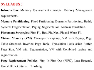
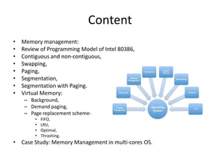
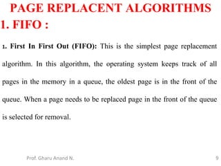
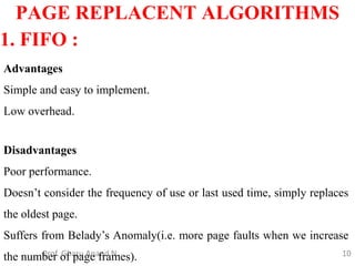
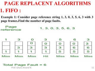
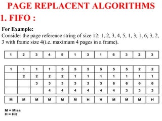
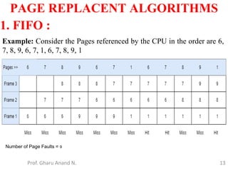
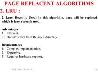
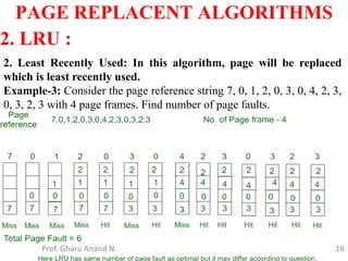
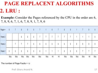
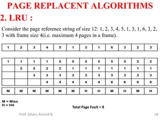
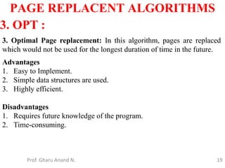
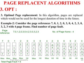
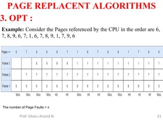
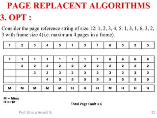
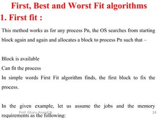
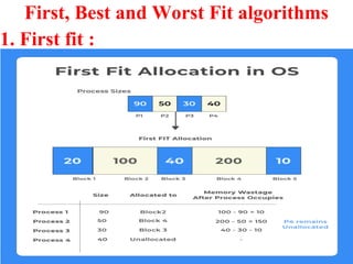
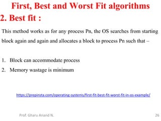
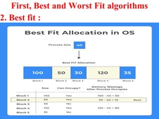
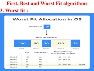
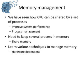
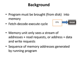
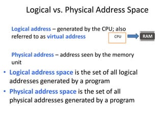
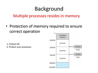
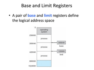
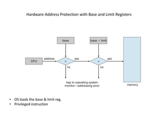
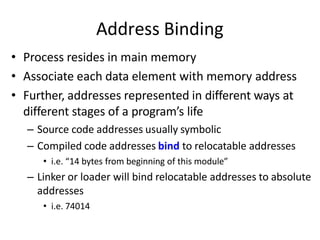
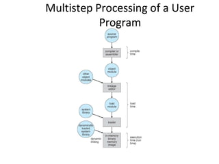
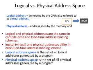
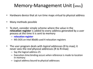
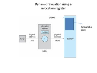
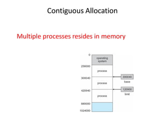
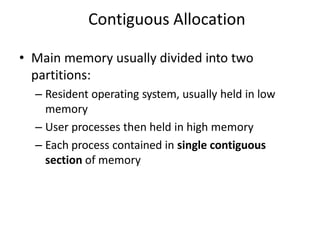
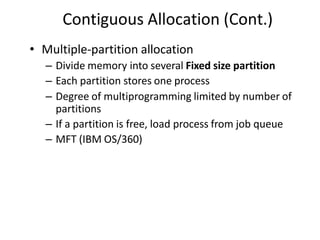
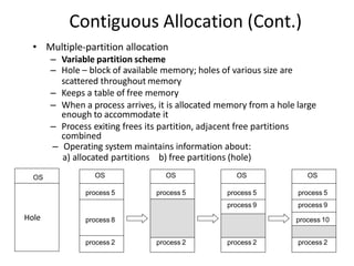
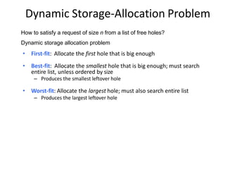
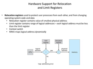
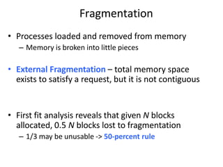
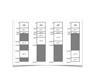
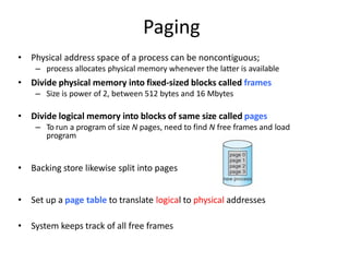
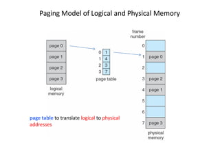
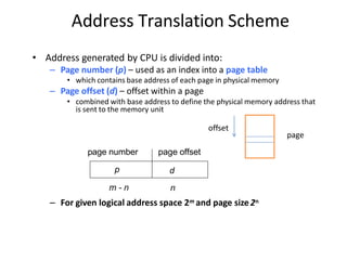
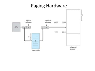
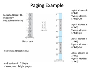
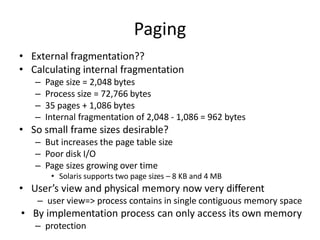
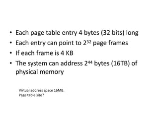
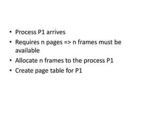
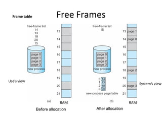
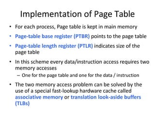
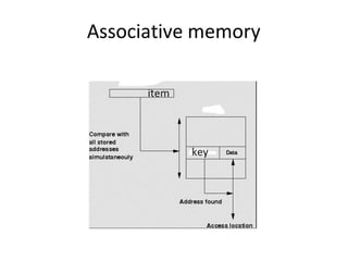
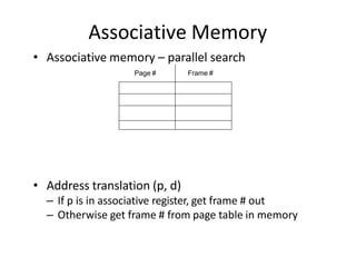
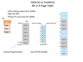
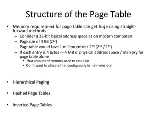
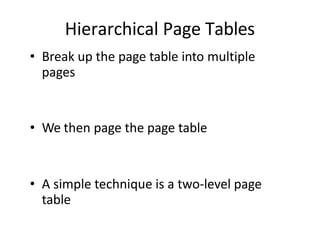
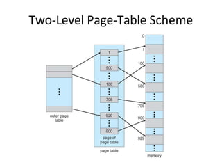
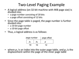
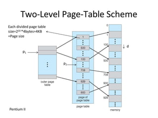
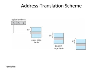
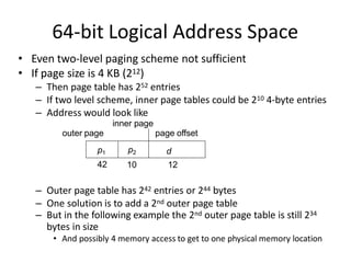
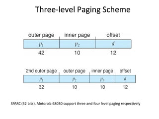
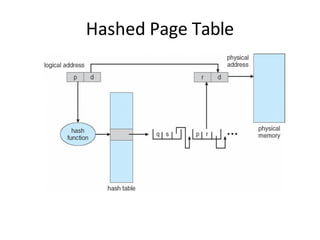
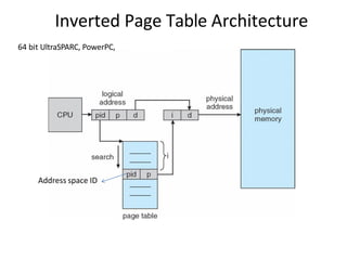
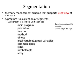
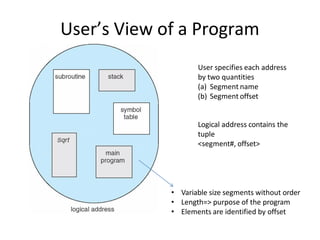
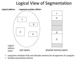
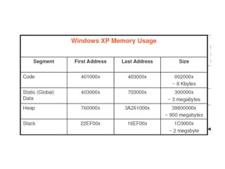
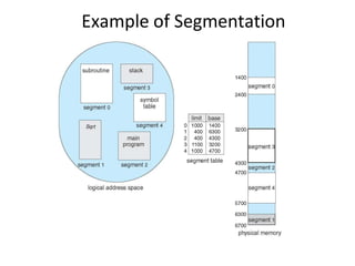
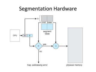
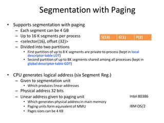
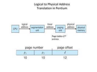
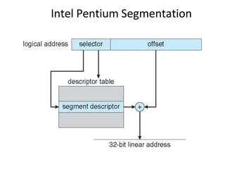
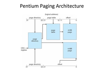
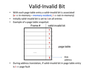
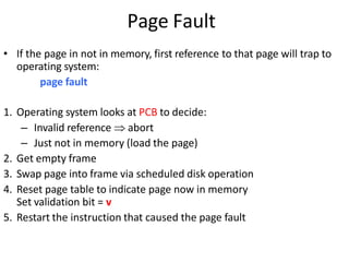
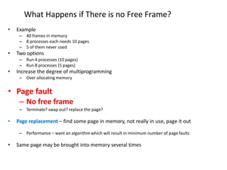
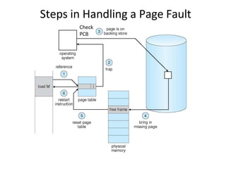
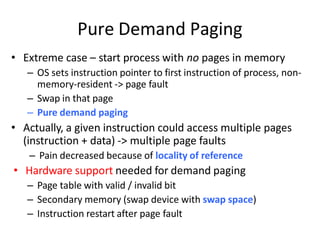
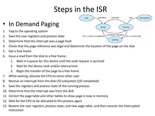
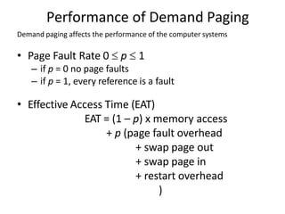
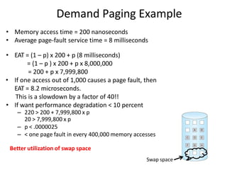
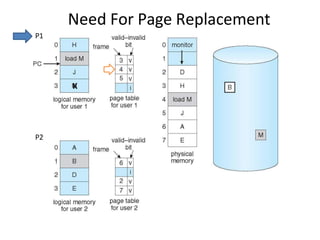
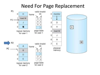
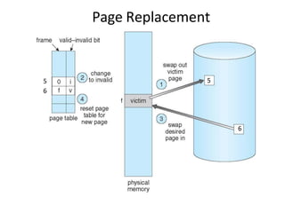
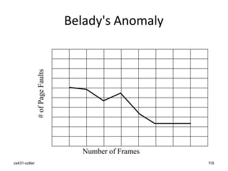
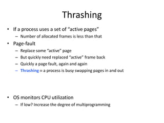
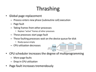
“MEMORY MANAGEMENT”
Prepared By
Prof. Anand N. Gharu
(Assistant Professor)
Computer Dept.
05 NOV 2022
.
CLASS : TE COMPUTER 2019
SUBJECT : SPOS (SEM-I)
UNIT : VI
Memory Management
Source: cse.iitkgp.ac.in/~bivasm/os_notes/memory_v3.pptx
SYLLABUS :
Introduction: Memory Management concepts, Memory Management
requirements.
Memory Partitioning: Fixed Partitioning, Dynamic Partitioning, Buddy
Systems Fragmentation, Paging, Segmentation, Address translation.
Placement Strategies: First Fit, Best Fit, Next Fit and Worst Fit.
Virtual Memory (VM): Concepts, Swapping, VM with Paging, Page
Table Structure, Inverted Page Table, Translation Look aside Buffer,
Page Size, VM with Segmentation, VM with Combined paging and
segmentation.
Page Replacement Policies: First In First Out (FIFO), Last Recently
Used(LRU), Optimal, Thrashing.
Content
• Memory management:
• Review of Programming Model of Intel 80386,
• Contiguous and non-contiguous,
• Swapping,
• Paging,
• Segmentation,
• Segmentation with Paging.
• Virtual Memory:
– Background,
– Demand paging,
– Page replacement scheme-
• FIFO,
• LRU,
• Optimal,
• Thrashing.
• Case Study: Memory Management in multi-cores OS.
PAGE
REPLACEMENT
ALGORITHM
Prof. Gharu Anand N. 5
6
PAGE REPLACENT ALGORITHMS
1. FIFO Page Replacement Algorithm
2. LIFO Page Replacement Algorithm
3. LRU Page Replacement Algorithm
4. Optimal Page Replacement Algorithm
5. Random Page Replacement Algorithm
7
PAGE REPLACENT ALGORITHMS
Prof. Gharu Anand N.
1. FIFO Page Replacement Algorithm-
• As the name suggests, this algorithm works on the principle of “First in
First out“.
• It replaces the oldest page that has been present in the main memory for
the longest time.
• It is implemented by keeping track of all the pages in a queue.
2. LRU Page Replacement Algorithm –
As the name suggests, this algorithm works on the principle of “Last in
First out“.
It replaces the newest page that arrived at last in the main memory.
It is implemented by keeping track of all the pages in a stack.
8
PAGE REPLACENT ALGORITHMS
Prof. Gharu Anand N.
3. Optimal Page Replacement Algorithm-
• This algorithm replaces the page that will not be referred by the CPU
in future for the longest time.
• It is practically impossible to implement this algorithm.
• This is because the pages that will not be used in future for the longest
time can not be predicted.
• However, it is the best known algorithm and gives the least number of
page faults.
• Hence, it is used as a performance measure criterion for other
algorithms.
9
PAGE REPLACENT ALGORITHMS
Prof. Gharu Anand N.
1. FIFO :
1. First In First Out (FIFO): This is the simplest page replacement
algorithm. In this algorithm, the operating system keeps track of all
pages in the memory in a queue, the oldest page is in the front of the
queue. When a page needs to be replaced page in the front of the queue
is selected for removal.
10
PAGE REPLACENT ALGORITHMS
Prof. Gharu Anand N.
1. FIFO :
Advantages
Simple and easy to implement.
Low overhead.
Disadvantages
Poor performance.
Doesn’t consider the frequency of use or last used time, simply replaces
the oldest page.
Suffers from Belady’s Anomaly(i.e. more page faults when we increase
the number of page frames).
11
PAGE REPLACENT ALGORITHMS
Prof. Gharu Anand N.
1. FIFO :
Example 1: Consider page reference string 1, 3, 0, 3, 5, 6, 3 with 3
page frames.Find the number of page faults.
12
PAGE REPLACENT ALGORITHMS
Prof. Gharu Anand N.
1. FIFO :
For Example:
Consider the page reference string of size 12: 1, 2, 3, 4, 5, 1, 3, 1, 6, 3, 2,
3 with frame size 4(i.e. maximum 4 pages in a frame).
Total Page Fault = 9
13
PAGE REPLACENT ALGORITHMS
Prof. Gharu Anand N.
1. FIFO :
Example: Consider the Pages referenced by the CPU in the order are 6,
7, 8, 9, 6, 7, 1, 6, 7, 8, 9, 1
Number of Page Faults = 9
14
PAGE REPLACENT ALGORITHMS
Prof. Gharu Anand N.
1. FIFO :
Example: Consider the Pages referenced by the CPU in the order are 6,
7, 8, 9, 6, 7, 1, 6, 7, 8, 9, 1
15
PAGE REPLACENT ALGORITHMS
Prof. Gharu Anand N.
2. LRU :
2. Least Recently Used: In this algorithm, page will be replaced
which is least recently used.
Advantages
1. Efficient.
2. Doesn't suffer from Belady’s Anomaly.
Disadvantages
1. Complex Implementation.
2. Expensive.
3. Requires hardware support.
16
PAGE REPLACENT ALGORITHMS
Prof. Gharu Anand N.
2. LRU :
2. Least Recently Used: In this algorithm, page will be replaced
which is least recently used.
Example-3: Consider the page reference string 7, 0, 1, 2, 0, 3, 0, 4, 2, 3,
0, 3, 2, 3 with 4 page frames. Find number of page faults.
17
PAGE REPLACENT ALGORITHMS
Prof. Gharu Anand N.
2. LRU :
Example: Consider the Pages referenced by the CPU in the order are 6,
7, 8, 9, 6, 7, 1, 6, 7, 8, 9, 1, 7, 9, 6
The number of Page Faults = 12
18
PAGE REPLACENT ALGORITHMS
Prof. Gharu Anand N.
2. LRU :
Consider the page reference string of size 12: 1, 2, 3, 4, 5, 1, 3, 1, 6, 3, 2,
3 with frame size 4(i.e. maximum 4 pages in a frame).
Total Page Fault = 8
19
PAGE REPLACENT ALGORITHMS
Prof. Gharu Anand N.
3. OPT :
3. Optimal Page replacement: In this algorithm, pages are replaced
which would not be used for the longest duration of time in the future.
Advantages
1. Easy to Implement.
2. Simple data structures are used.
3. Highly efficient.
Disadvantages
1. Requires future knowledge of the program.
2. Time-consuming.
20
PAGE REPLACENT ALGORITHMS
Prof. Gharu Anand N.
3. OPT :
3. Optimal Page replacement: In this algorithm, pages are replaced
which would not be used for the longest duration of time in the future.
Example-2: Consider the page references 7, 0, 1, 2, 0, 3, 0, 4, 2, 3, 0,
3, 2, 3 with 4 page frame. Find number of page fault.
21
PAGE REPLACENT ALGORITHMS
Prof. Gharu Anand N.
3. OPT :
Example: Consider the Pages referenced by the CPU in the order are 6,
7, 8, 9, 6, 7, 1, 6, 7, 8, 9, 1, 7, 9, 6
The number of Page Faults = 8
22
PAGE REPLACENT ALGORITHMS
Prof. Gharu Anand N.
3. OPT :
Consider the page reference string of size 12: 1, 2, 3, 4, 5, 1, 3, 1, 6, 3, 2,
3 with frame size 4(i.e. maximum 4 pages in a frame).
Total Page Fault = 6
23
First, Best and Worst Fit algorithms
Prof. Gharu Anand N.
Processes need execution time/storage space in memory blocks. OS has
various algorithms to allocate in-coming processes to available memory
blocks.
The following are the most used algorithms –
1. First Fit
2. Best Fit
3. Worst Fit
24
First, Best and Worst Fit algorithms
Prof. Gharu Anand N.
1. First fit :
This method works as for any process Pn, the OS searches from starting
block again and again and allocates a block to process Pn such that –
Block is available
Can fit the process
In simple words First Fit algorithm finds, the first block to fix the
process.
In the given example, let us assume the jobs and the memory
requirements as the following:
25
First, Best and Worst Fit algorithms
Prof. Gharu Anand N.
1. First fit :
26
First, Best and Worst Fit algorithms
Prof. Gharu Anand N.
2. Best fit :
This method works as for any process Pn, the OS searches from starting
block again and again and allocates a block to process Pn such that –
1. Block can accommodate process
2. Memory wastage is minimum
https://prepinsta.com/operating-systems/first-fit-best-fit-worst-fit-in-os-example/
27
First, Best and Worst Fit algorithms
Prof. Gharu Anand N.
2. Best fit :
28
First, Best and Worst Fit algorithms
Prof. Gharu Anand N.
3. Worst fit :
This method works as for any process Pn, the OS searches from starting
block again and again and allocates a block to process Pn such that –
1. Block can accommodate process
2. Memory wastage is maximum
29
First, Best and Worst Fit algorithms
Prof. Gharu Anand N.
3. Worst fit :
• We have seen how CPU can be shared by a set
of processes
– Improve system performance
– Process management
• Need to keep several process in memory
– Share memory
• Learn various techniques to manage memory
– Hardware dependent
Memory management
Memory management
What are we going to learn?
• Basic Memory Management: logical vs.
physical address space, protection, contiguous
memory allocation, paging, segmentation,
segmentation with paging.
• Virtual Memory: background, demand paging,
performance, page replacement, page
replacement algorithms (FCFS, LRU), allocation
of frames, thrashing.
Review of Programming Model of
80386
Background
• Program must be brought (from disk) into
memory
• Fetch-decode-execute cycle
• Memory unit only sees a stream of
addresses + read requests, or address + data
and write requests
• Sequence of memory addresses generated
by running program
CPU
Logical vs. Physical Address Space
Logical address – generated by the CPU; also
referred to as virtual address
Physical address – address seen by the memory
unit
• Logical address space is the set of all logical
addresses generated by a program
• Physical address space is the set of all
physical addresses generated by a program
CPU
• Protection of memory required to ensure
correct operation
Background
Multiple processes resides in memory
1. Protect OS
2. Protect user processes
Base and Limit Registers
• A pair of base and limit registers define
the logical address space
Hardware Address Protection with Base and Limit Registers
• OS loads the base & limit reg.
• Privileged instruction
Address Binding
• Process resides in main memory
• Associate each data element with memory address
• Further, addresses represented in different ways at
different stages of a program’s life
– Source code addresses usually symbolic
– Compiled code addresses bind to relocatable addresses
• i.e. “14 bytes from beginning of this module”
– Linker or loader will bind relocatable addresses to absolute
addresses
• i.e. 74014
Multistep Processing of a User
Program
Binding of Instructions and Data to
Memory
• Address binding of instructions and data to memory
addresses can happen at three different stages
– Compile time: If memory location known a priori,
absolute code can be generated; must recompile code if
starting location changes
– Load time: Must generate relocatable code if memory
location is not known at compile time
– Execution time: If the process can be moved during its
execution from one memory segment to another
• Binding delayed until run time
• Need hardware support for address maps (e.g., base and limit
registers)
Logical vs. Physical Address Space
Logical address – generated by the CPU; also referred to
as virtual address
Physical address – address seen by the memory unit
• Logical and physical addresses are the same in
compile-time and load-time address-binding
schemes;
• logical (virtual) and physical addresses differ in
execution-time address-binding scheme
• Logical address space is the set of all logical
addresses generated by a program
• Physical address space is the set of all physical
addresses generated by a program
CPU
Memory-Management Unit (MMU)
• Hardware device that at run time maps virtual to physical address
• Many methods possible
• To start, consider simple scheme where the value in the
relocation register is added to every address generated by a user
process at the time it is sent to memory
– relocation register
– MS-DOS on Intel 80x86 used 4 relocation registers
• The user program deals with logical addresses (0 to max); it
never sees the real physical addresses (R to R+max)
– Say the logical address 25
– Execution-time binding occurs when reference is made to location
in memory
– Logical address bound to physical addresses
Dynamic relocation using a
relocation register
Relocatable
code
14000
Multiple processes resides in memory
Contiguous Allocation
• Main memory usually divided into two
partitions:
– Resident operating system, usually held in low
memory
– User processes then held in high memory
– Each process contained in single contiguous
section of memory
Contiguous Allocation (Cont.)
• Multiple-partition allocation
– Divide memory into several Fixed size partition
– Each partition stores one process
– Degree of multiprogramming limited by number of
partitions
– If a partition is free, load process from job queue
– MFT (IBM OS/360)
Contiguous Allocation (Cont.)
• Multiple-partition allocation
– Variable partition scheme
– Hole – block of available memory; holes of various size are
scattered throughout memory
– Keeps a table of free memory
– When a process arrives, it is allocated memory from a hole large
enough to accommodate it
– Process exiting frees its partition, adjacent free partitions
combined
– Operating system maintains information about:
a) allocated partitions b) free partitions (hole)
OS
process 5
process 8
process 2
OS
process 5
process 2
OS
process 5
process 9
process 2
OS
process 5
process 9
process 10
process 2
OS
Hole
Dynamic Storage-Allocation Problem
How to satisfy a request of size n from a list of free holes?
Dynamic storage allocation problem
• First-fit: Allocate the first hole that is big enough
• Best-fit: Allocate the smallest hole that is big enough; must search
entire list, unless ordered by size
– Produces the smallest leftover hole
• Worst-fit: Allocate the largest hole; must also search entire list
– Produces the largest leftover hole
Hardware Support for Relocation
and Limit Registers
• Relocation registers used to protect user processes from each other, and from changing
operating-system code and data
• Relocation register contains value of smallest physical address
• Limit register contains range of logical addresses – each logical address must be less
than the limit register
• Context switch
• MMU maps logical address dynamically
Fragmentation
• Processes loaded and removed from memory
– Memory is broken into little pieces
• External Fragmentation – total memory space
exists to satisfy a request, but it is not contiguous
• First fit analysis reveals that given N blocks
allocated, 0.5 N blocks lost to fragmentation
– 1/3 may be unusable -> 50-percent rule
Fragmentation (Cont.)
• Reduce external fragmentation by compaction
– Shuffle memory contents to place all free memory
together in one large block
– Compaction is possible only if relocation is dynamic,
and is done at execution time
• Change relocation reg.
– Cost
• Internal Fragmentation – allocated memory may
be slightly larger than requested memory; this size
difference is memory internal to a partition, but
not being used
Paging
• Physical address space of a process can be noncontiguous;
– process allocates physical memory whenever the latter is available
• Divide physical memory into fixed-sized blocks called frames
– Size is power of 2, between 512 bytes and 16 Mbytes
• Divide logical memory into blocks of same size called pages
– To run a program of size N pages, need to find N free frames and load
program
• Backing store likewise split into pages
• Set up a page table to translate logical to physical addresses
• System keeps track of all free frames
Paging Model of Logical and Physical Memory
page table to translate logical to physical
addresses
Address Translation Scheme
• Address generated by CPU is divided into:
– Page number (p) – used as an index into a page table
• which contains base address of each page in physical memory
– Page offset (d) – offset within a page
• combined with base address to define the physical memory address that
is sent to the memory unit
age number page offset
p d
p
m - n n
– For given logical address space 2m and page size2n
offset
page
Paging Hardware
Paging Example
n=2 and m=4 32-byte
memory and 4-byte pages
Logical address = 16
Page size=4
Physical memory=32
User’s view
Logical address 0
(0*4+0)
Physical address:
(5*4+0)=20
Logical address 3
(0*4+3)
Physical address:
(5*4+0)=23
Logical address 4
(1*4+0)
Physical address:
(6*4+0)=24
Logical address 13
(3*4+1)
Physical address:
(2*4+1)
Run time address binding
Paging
• External fragmentation??
• Calculating internal fragmentation
– Page size = 2,048 bytes
– Process size = 72,766 bytes
– 35 pages + 1,086 bytes
– Internal fragmentation of 2,048 - 1,086 = 962 bytes
• So small frame sizes desirable?
– But increases the page table size
– Poor disk I/O
– Page sizes growing over time
• Solaris supports two page sizes – 8 KB and 4 MB
• User’s view and physical memory now very different
– user view=> process contains in single contiguous memory space
• By implementation process can only access its own memory
– protection
• Each page table entry 4 bytes (32 bits) long
• Each entry can point to 232 page frames
• If each frame is 4 KB
• The system can address 244 bytes (16TB) of
physical memory
Virtual address space 16MB.
Page table size?
• Process P1 arrives
• Requires n pages => n frames must be
available
• Allocate n frames to the process P1
• Create page table for P1
Free Frames
After allocation
RAM
Before allocation
Frame table
RAM
Use’s view
System’s view
Implementation of Page Table
• For each process, Page table is kept in main memory
• Page-table base register (PTBR) points to the page table
• Page-table length register (PTLR) indicates size of the
page table
• In this scheme every data/instruction access requires two
memory accesses
– One for the page table and one for the data / instruction
• The two memory access problem can be solved by the
use of a special fast-lookup hardware cache called
associative memory or translation look-aside buffers
(TLBs)
Associative memory
Associative Memory
• Associative memory – parallel search
• Address translation (p, d)
– If p is in associative register, get frame # out
– Otherwise get frame # from page table in memory
Page # Frame #
Implementation of Page Table
• For each process, Page table is kept in main memory
• Page-table base register (PTBR) points to the page table
• Page-table length register (PTLR) indicates size of the page table
• In this scheme every data/instruction access requires two memory accesses
– One for the page table and one for the data / instruction
• The two memory access problem can be solved by the use of a special fast-lookup
hardware cache called associative memory or translation look-aside buffers (TLBs)
• TLBs typically small (64 to 1,024 entries)
• On a TLB miss, value is loaded into the TLB for faster access next time
– Replacement policies must be considered (LRU)
– Some entries can be wired down for permanent fast access
• Some TLBs store address-space identifiers (ASIDs) in each TLB entry – uniquely
identifies each process (PID) to provide address-space protection for that process
– Otherwise need to flush at every context switch
Paging Hardware With TLB
Effective Access Time
• Associative Lookup =  time unit
– Can be < 10% of memory access time
• Hit ratio = 
– Hit ratio – percentage of times that a page number is found in the
associative registers; ratio related to size of TLB
• Consider  = 80%,  = 20ns for TLB search, 100ns for memory access
• Effective Access Time (EAT)
EAT = (100 + )  + (200 + )(1 – )
• Consider  = 80%,  = 20ns for TLB search, 100ns for memory access
– EAT = 0.80 x 120 + 0.20 x 220 = 140ns
• Consider better hit ratio ->  = 98%,  = 20ns for TLB search, 100ns for
memory access
– EAT = 0.98 x 120 + 0.02 x 220 = 122ns
Memory Protection
• Memory protection implemented by associating protection bit
with each frame to indicate if read-only or read-write access is
allowed
– Can also add more bits to indicate page execute-only, and so on
• Valid-invalid bit attached to each entry in the page table:
– “valid” indicates that the associated page is in the process’ logical
address space, and is thus a legal page
– “invalid” indicates that the page is not in the process’ logical
address space
– Or use PTLR
• Any violations result in a trap to the kernel
Valid (v) or Invalid (i)
Bit In A Page Table
14 bit address space (0 to 16383)
Page size 2KB
Process P1 uses only 0 to 10468
Internal fragmentation Use of PTLR (length)
Page 0
Page 1
Page 2
Page 3
P1
P2
• System with 40 users
– Use common text editor
• Text editor contains 150KB code 50KB data (page size 50KB)
– 8000KB!
• Shared code
– One copy of read-only (reentrant) code shared among
processes (i.e., text editors, compilers, window systems)
• Code never changes during execution
• Only one copy of the editor in the memory
• Total memory consumption
– 40*50+150=2150KB
Shared Pages Example
Data share: example
int main()
{
int shmid,f,key=3,i,pid;
char *ptr;
shmid=shmget((key_t)key,100,IPC_CREAT|0666);
ptr=shmat(shmid,NULL,0);
printf("shmid=%d ptr=%un",shmid, ptr);
strcpy(ptr,"hello");
i=shmdt((char*)ptr);
}
int main()
{
int shmid,f,key=3,i,pid;
char *ptr;
shmid=shmget((key_t)key,100,IPC_CREAT|0666);
ptr=shmat(shmid,NULL,0);
printf("shmid=%d ptr=%un",shmid, ptr);
printf("nstr %sn",ptr);
}
writer
.c
reader .c
ptr
Shared
memory
Structure of the Page Table
• Memory requirement for page table can get huge using straight-
forward methods
– Consider a 32-bit logical address space as on modern computers
– Page size of 4 KB (212)
– Page table would have 1 million entries 220 (232 / 212)
– If each entry is 4 bytes -> 4 MB of physical address space / memory for
page table alone
• That amount of memory used to cost a lot
• Don’t want to allocate that contiguously in main memory
• Hierarchical Paging
• Hashed Page Tables
• Inverted Page Tables
Hierarchical Page Tables
• Break up the page table into multiple
pages
• We then page the page table
• A simple technique is a two-level page
table
Two-Level Page-Table Scheme
Two-Level Paging Example
displacement within the page of the inner page table
age number page offset
p1 p2 d
• A logical address (on 32-bit machine with 4KB page size) is
divided into:
– a page number consisting of 20 bits
– a page offset consisting of 12 bits
• Since the page table is paged, the page number is further
divided into:
– a 10-bit page number
– a 10-bit page offset
• Thus, a logical address is as follows:
p
10 10 12
• where p1 is an index into the outer page table, and p2 is the
Two-Level Page-Table Scheme
p1
p2
d
Each divided page table
size=210 *4bytes=4KB
=Page size
Pentium II
Address-Translation Scheme
Pentium II
64-bit Logical Address Space
• Even two-level paging scheme not sufficient
• If page size is 4 KB (212)
– Then page table has 252 entries
– If two level scheme, inner page tables could be 210 4-byte entries
– Address would look like
42 10 12
– Outer page table has 242 entries or 244 bytes
– One solution is to add a 2nd outer page table
– But in the following example the 2nd outer page table is still 234
bytes in size
• And possibly 4 memory access to get to one physical memory location
outer page
p1 p2 d
inner page
page offset
Three-level Paging Scheme
SPARC (32 bits), Motorola 68030 support three and four level paging respectively
Hashed Page Tables
• Common in virtual address spaces > 32 bits
• The page number is hashed into a page table
– This page table contains a chain of elements hashing to the same
location
• Each element contains (1) the page number (2) the value of the
mapped page frame (3) a pointer to the next element
• Virtual page numbers are compared in this chain searching for a
match
– If a match is found, the corresponding physical frame is extracted
Hashed Page Table
Inverted Page Table
• Rather than each process having a page table and
keeping track of all possible logical pages, track all frames
• One entry for each frame
• Entry consists the page number stored in that frame, with
information about the process that owns that page
• Decreases memory needed to store each page table,
– but increases time needed to search the table when a page
reference occurs
Inverted Page Table Architecture
64 bit UltraSPARC, PowerPC,
Address space ID
Segmentation
main program
procedure
function
method
object
local variables, global variables
common block
stack
symbol table
arrays
• Memory-management scheme that supports user view of
memory
• A program is a collection of segments
– A segment is a logical unit such as:
Compiler generates the
segments
Loader assign the seg#
User’s View of a Program
User specifies each address
by two quantities
(a) Segment name
(b) Segment offset
Logical address contains the
tuple
<segment#, offset>
• Variable size segments without order
• Length=> purpose of the program
• Elements are identified by offset
Logical View of Segmentation
1
3
2
4
1
4
2
3
user space physical memory space
• Long term scheduler finds and allocates memory for all segments of a program
• Variable size partition scheme
Logical
address
space
Logical address <segment-number, offset>
Memory image
Executable file and virtual address
Virtual address
space
a.out
Symbol table
Name address
SQR 0
SUM 4
0
4
Load
ADD
0
4
<CODE, 0>
<CODE, 2>
Load
ADD
<ST
,0>
<ST
,4>
Paging view
Segmentation view
Segmentation Architecture
• Logical address consists of a two tuple:
<segment-number, offset>
• Segment table – maps two-dimensional logical address
to physical address;
• Each table entry has:
– base – contains the starting physical address where the
segments reside in memory
– limit – specifies the length of the segment
• Segment-table base register (STBR) points to the
segment table’s location in memory
• Segment-table length register (STLR) indicates number
of segments used by a program;
segment number s is legal if s < STLR
Example of Segmentation
Segmentation Hardware
Example of Segmentation
Segmentation Architecture
• Protection
• Protection bits associated with segments
– With each entry in segment table associate:
• validation bit = 0  illegal segment
• read/write/execute privileges
• Code sharing occurs at segment level
• Since segments vary in length, memory allocation is
a dynamic storage-allocation problem
– Long term scheduler
– First fit, best fit etc
• Fragmentation
Segmentation with Paging
Key idea:
Segments are splitted into multiple pages
Each page is loaded into frames in the memory
Segmentation with Paging
• Supports segmentation with paging
– Each segment can be 4 GB
– Up to 16 K segments per process
– <selector(16), offset (32)>
– Divided into two partitions
• First partition of up to 8 K segments are private to process (kept in local
descriptor table LDT)
• Second partition of up to 8K segments shared among all processes (kept in
global descriptor table GDT)
• CPU generates logical address (six Segment Reg.)
– Given to segmentation unit
• Which produces linear addresses
– Physical address 32 bits
– Linear address given to paging unit
• Which generates physical address in main memory
• Paging units form equivalent of MMU
• Pages sizes can be 4 KB
Intel 80386
IBM OS/2
S(13) G(1) P(2)
Logical to Physical Address
Translation in Pentium
Page table=220
entries
Example: The Intel Pentium
8 bytes Segment register
Intel Pentium Segmentation
Pentium Paging Architecture
Virtual Memory
Background
• Code needs to be in memory to execute, but
entire program rarely used
– Error code, unusual routines, large data structures
• Entire program code not needed at same time
• Consider ability to execute partially-loaded
program
– Program no longer constrained by limits of physical
memory
– programs could be larger than physical memory
– More processes can be accommodated
Virtual Memory That is
Larger Than Physical Memory
Large virtual
space
Small memory
Classical paging
• Process P1 arrives
• Requires n pages => n frames must be
available
• Allocate n frames to the process P1
• Create page table for P1
Allocate < n frames
Background
• Virtual memory – separation of user logical memory from
physical memory
– Extremely large logical space is available to programmer
– Concentrate on the problem
• Only part of the program needs to be in memory for
execution
– Logical address space can therefore be much larger than physical
address space
– Starts with address 0, allocates contiguous logical memory
– Physical memory
• Collection of frame
• Virtual memory can be implemented via:
– Demand paging
– Demand segmentation
Demand Paging
• Bring a page into memory only when it is needed
• Lazy swapper – never swaps a page into memory
unless page will be needed
– Swapper that deals with pages is a pager
• Less I/O needed, no unnecessary I/O
– Less memory needed
– More users
• Page is needed  reference to it
– invalid reference  abort
– not-in-memory  bring to memory
Valid address
information is available
in PCB
Transfer of a Paged Memory to
Contiguous Disk Space
• When we want to
execute a process, swap
in
• Instead of swap in entire
process, load page
• Pager
Page Table When Some Pages
Are Not in Main Memory
Pager loads few necessary pages in
memory
Valid-Invalid Bit
• During address translation, if valid–invalid bit in page table entry
is i  page fault
i
ii
….
• With each page table entry a valid–invalid bit is associated
(v  in-memory – memory resident, i  not-in-memory)
• Initially valid–invalid bit is set to i on all entries
• Example of a page table snapshot:
Frame # valid-invalid bit
v
v
v
v
page table
Disk
address
Page Fault
• If the page in not in memory, first reference to that page will trap to
operating system:
page fault
1. Operating system looks at PCB to decide:
– Invalid reference  abort
– Just not in memory (load the page)
2. Get empty frame
3. Swap page into frame via scheduled disk operation
4. Reset page table to indicate page now in memory
Set validation bit = v
5. Restart the instruction that caused the page fault
What Happens if There is no Free Frame?
• Example
– 40 frames in memory
– 8 processes each needs 10 pages
– 5 of them never used
• Two options
– Run 4 processes (10 pages)
– Run 8 processes (5 pages)
• Increase the degree of multiprogramming
– Over allocating memory
• Page fault
– No free frame
– Terminate? swap out? replace the page?
• Page replacement – find some page in memory, not really in use, page it out
– Performance – want an algorithm which will result in minimum number of page faults
• Same page may be brought into memory several times
Steps in Handling a Page Fault
Check
PCB
Pure Demand Paging
• Extreme case – start process with no pages in memory
– OS sets instruction pointer to first instruction of process, non-
memory-resident -> page fault
– Swap in that page
– Pure demand paging
• Actually, a given instruction could access multiple pages
(instruction + data) -> multiple page faults
– Pain decreased because of locality of reference
• Hardware support needed for demand paging
– Page table with valid / invalid bit
– Secondary memory (swap device with swap space)
– Instruction restart after page fault
Steps in the ISR
• In Demand Paging
1. Trap to the operating system
2. Save the user registers and process state
3. Determine that the interrupt was a page fault
4. Check that the page reference was legal and determine the location of the page on the disk
5. Get a free frame
6. Issue a read from the disk to a free frame:
1. Wait in a queue for this device until the read request is serviced
2. Wait for the device seek and/or latency time
3. Begin the transfer of the page to a free frame
7. While waiting, allocate the CPU to some other user
8. Receive an interrupt from the disk I/O subsystem (I/O completed)
9. Save the registers and process state of the running process
10. Determine that the interrupt was from the disk
11. Correct the page table and other tables to show page is now in memory
12. Wait for the CPU to be allocated to this process again
13. Restore the user registers, process state, and new page table, and then resume the interrupted
instruction
Performance of Demand Paging
Demand paging affects the performance of the computer systems
• Page Fault Rate 0  p  1
– if p = 0 no page faults
– if p = 1, every reference is a fault
• Effective Access Time (EAT)
EAT = (1 – p) x memory access
+ p (page fault overhead
+ swap page out
+ swap page in
+ restart overhead
)
Demand Paging Example
• Memory access time = 200 nanoseconds
• Average page-fault service time = 8 milliseconds
• EAT = (1 – p) x 200 + p (8 milliseconds)
= (1 – p ) x 200 + p x 8,000,000
= 200 + p x 7,999,800
• If one access out of 1,000 causes a page fault, then
EAT = 8.2 microseconds.
This is a slowdown by a factor of 40!!
• If want performance degradation < 10 percent
– 220 > 200 + 7,999,800 x p
20 > 7,999,800 x p
– p < .0000025
– < one page fault in every 400,000 memory accesses
Better utilization of swap space
Swap space
Allocation of Frames
• How do we allocate the fixed amount of
memory among various processes?
• Single user system
– Trivial
Allocation of Frames
• Each process needs minimum number of frames
• Minimum number is defined by the instruction set
• Page fault forces to restart the instruction
– Enough frames to hold all the pages for that instruction
• Example:
– Single address instruction (2 frames)
– Two address instruction (3 frames)
• Maximum of course is total frames in the system
• Two major allocation schemes
– fixed allocation
– proportional allocation
Fixed and proportional Allocation
• Equal allocation – m frames and n processes
– Each process gets m/n
• For example, if there are 100 frames (after allocating frames
for the OS) and 5 processes, give each process 20 frames
– Keep some as free frame buffer pool
• Unfair for small and large sized processes
• Proportional allocation – Allocate according to the size of
process
– Dynamic as degree of multiprogramming, process sizes
change
si  size of process pi
S  si
m  totalnumber of frames
S
si
i i
a  allocation for p   m
m  64
s1 10
s2 127
1
137
a 
10
 64  5
2
137
a 
127
 64  59
Priority Allocation
Allocation of frames
• Depends on multiprogramming level
• Use a proportional allocation scheme using
priorities along with size
Need For Page Replacement
P1
P2
K
Need For Page Replacement
P1
P2
PC
K
Basic Page Replacement
1. Find the location of the desired page on disk
2. Find a free frame:
- If there is a free frame, use it
- If there is no free frame, use a page replacement algorithm to
select a victim frame (of that process)
- Write victim frame to disk
3. Bring the desired page into the (newly) free frame; update the page
and frame tables
4. Continue the process by restarting the instruction that caused the trap
Note now potentially 2 page transfers for page fault – increasing Effective
memory access time
Page Replacement
5
6
5
6
Page Replacement
5
6
6
5
cs431-cotter 118
Belady's Anomaly
#
of
Page
Faults
Number of Frames
Belady’s Anomaly
• This most unexpected result is known as
Belady’s anomaly – for some page-
replacement algorithms, the page fault rate
may increase as the number of allocated
frames increases
• Is there a characterization of algorithms
susceptible to Belady’s anomaly?
Global vs. Local Allocation
• Frames are allocated to various processes
• If process Pi generates a page fault
– select for replacement one of its frames
– select for replacement a frame from another process
• Local replacement – each process selects from only its own set of
allocated frames
– More consistent per-process performance
– But possibly underutilized memory
• Global replacement – process selects a replacement frame from the
set of all frames; one process can take a frame from another
– But then process execution time can vary greatly
– But greater throughput ----- so more common
• Processes can not control its own page fault rate
– Depends on the paging behavior of other processes
Thrashing
• If a process uses a set of “active pages”
– Number of allocated frames is less than that
• Page-fault
– Replace some “active” page
– But quickly need replaced “active” frame back
– Quickly a page fault, again and again
– Thrashing  a process is busy swapping pages in and out
• OS monitors CPU utilization
– If low? Increase the degree of multiprogramming
• Global page replacement
– Process enters new phase (subroutine call) execution
– Page fault
– Taking frames from other processes
• Replace “active” frames of other processes
– These processes start page fault
– These faulting processes wait on the device queue for disk
• Ready queue empty
– CPU utilization decreases
• CPU scheduler increases the degree of multiprogramming
– More page faults
– Drop in CPU utilization
• Page fault increases tremendously
Disk
Thrashing
THANK YOU!!!
My Blog : https://anandgharu.wordpress.com/
Email : gharu.anand@gmail.com

final_unit_6_spos_notes_2023/24 pattern.pdf

  • 1.
    “MEMORY MANAGEMENT” Prepared By Prof.Anand N. Gharu (Assistant Professor) Computer Dept. 05 NOV 2022 . CLASS : TE COMPUTER 2019 SUBJECT : SPOS (SEM-I) UNIT : VI
  • 2.
  • 3.
    SYLLABUS : Introduction: MemoryManagement concepts, Memory Management requirements. Memory Partitioning: Fixed Partitioning, Dynamic Partitioning, Buddy Systems Fragmentation, Paging, Segmentation, Address translation. Placement Strategies: First Fit, Best Fit, Next Fit and Worst Fit. Virtual Memory (VM): Concepts, Swapping, VM with Paging, Page Table Structure, Inverted Page Table, Translation Look aside Buffer, Page Size, VM with Segmentation, VM with Combined paging and segmentation. Page Replacement Policies: First In First Out (FIFO), Last Recently Used(LRU), Optimal, Thrashing.
  • 4.
    Content • Memory management: •Review of Programming Model of Intel 80386, • Contiguous and non-contiguous, • Swapping, • Paging, • Segmentation, • Segmentation with Paging. • Virtual Memory: – Background, – Demand paging, – Page replacement scheme- • FIFO, • LRU, • Optimal, • Thrashing. • Case Study: Memory Management in multi-cores OS.
  • 5.
  • 6.
    6 PAGE REPLACENT ALGORITHMS 1.FIFO Page Replacement Algorithm 2. LIFO Page Replacement Algorithm 3. LRU Page Replacement Algorithm 4. Optimal Page Replacement Algorithm 5. Random Page Replacement Algorithm
  • 7.
    7 PAGE REPLACENT ALGORITHMS Prof.Gharu Anand N. 1. FIFO Page Replacement Algorithm- • As the name suggests, this algorithm works on the principle of “First in First out“. • It replaces the oldest page that has been present in the main memory for the longest time. • It is implemented by keeping track of all the pages in a queue. 2. LRU Page Replacement Algorithm – As the name suggests, this algorithm works on the principle of “Last in First out“. It replaces the newest page that arrived at last in the main memory. It is implemented by keeping track of all the pages in a stack.
  • 8.
    8 PAGE REPLACENT ALGORITHMS Prof.Gharu Anand N. 3. Optimal Page Replacement Algorithm- • This algorithm replaces the page that will not be referred by the CPU in future for the longest time. • It is practically impossible to implement this algorithm. • This is because the pages that will not be used in future for the longest time can not be predicted. • However, it is the best known algorithm and gives the least number of page faults. • Hence, it is used as a performance measure criterion for other algorithms.
  • 9.
    9 PAGE REPLACENT ALGORITHMS Prof.Gharu Anand N. 1. FIFO : 1. First In First Out (FIFO): This is the simplest page replacement algorithm. In this algorithm, the operating system keeps track of all pages in the memory in a queue, the oldest page is in the front of the queue. When a page needs to be replaced page in the front of the queue is selected for removal.
  • 10.
    10 PAGE REPLACENT ALGORITHMS Prof.Gharu Anand N. 1. FIFO : Advantages Simple and easy to implement. Low overhead. Disadvantages Poor performance. Doesn’t consider the frequency of use or last used time, simply replaces the oldest page. Suffers from Belady’s Anomaly(i.e. more page faults when we increase the number of page frames).
  • 11.
    11 PAGE REPLACENT ALGORITHMS Prof.Gharu Anand N. 1. FIFO : Example 1: Consider page reference string 1, 3, 0, 3, 5, 6, 3 with 3 page frames.Find the number of page faults.
  • 12.
    12 PAGE REPLACENT ALGORITHMS Prof.Gharu Anand N. 1. FIFO : For Example: Consider the page reference string of size 12: 1, 2, 3, 4, 5, 1, 3, 1, 6, 3, 2, 3 with frame size 4(i.e. maximum 4 pages in a frame). Total Page Fault = 9
  • 13.
    13 PAGE REPLACENT ALGORITHMS Prof.Gharu Anand N. 1. FIFO : Example: Consider the Pages referenced by the CPU in the order are 6, 7, 8, 9, 6, 7, 1, 6, 7, 8, 9, 1 Number of Page Faults = 9
  • 14.
    14 PAGE REPLACENT ALGORITHMS Prof.Gharu Anand N. 1. FIFO : Example: Consider the Pages referenced by the CPU in the order are 6, 7, 8, 9, 6, 7, 1, 6, 7, 8, 9, 1
  • 15.
    15 PAGE REPLACENT ALGORITHMS Prof.Gharu Anand N. 2. LRU : 2. Least Recently Used: In this algorithm, page will be replaced which is least recently used. Advantages 1. Efficient. 2. Doesn't suffer from Belady’s Anomaly. Disadvantages 1. Complex Implementation. 2. Expensive. 3. Requires hardware support.
  • 16.
    16 PAGE REPLACENT ALGORITHMS Prof.Gharu Anand N. 2. LRU : 2. Least Recently Used: In this algorithm, page will be replaced which is least recently used. Example-3: Consider the page reference string 7, 0, 1, 2, 0, 3, 0, 4, 2, 3, 0, 3, 2, 3 with 4 page frames. Find number of page faults.
  • 17.
    17 PAGE REPLACENT ALGORITHMS Prof.Gharu Anand N. 2. LRU : Example: Consider the Pages referenced by the CPU in the order are 6, 7, 8, 9, 6, 7, 1, 6, 7, 8, 9, 1, 7, 9, 6 The number of Page Faults = 12
  • 18.
    18 PAGE REPLACENT ALGORITHMS Prof.Gharu Anand N. 2. LRU : Consider the page reference string of size 12: 1, 2, 3, 4, 5, 1, 3, 1, 6, 3, 2, 3 with frame size 4(i.e. maximum 4 pages in a frame). Total Page Fault = 8
  • 19.
    19 PAGE REPLACENT ALGORITHMS Prof.Gharu Anand N. 3. OPT : 3. Optimal Page replacement: In this algorithm, pages are replaced which would not be used for the longest duration of time in the future. Advantages 1. Easy to Implement. 2. Simple data structures are used. 3. Highly efficient. Disadvantages 1. Requires future knowledge of the program. 2. Time-consuming.
  • 20.
    20 PAGE REPLACENT ALGORITHMS Prof.Gharu Anand N. 3. OPT : 3. Optimal Page replacement: In this algorithm, pages are replaced which would not be used for the longest duration of time in the future. Example-2: Consider the page references 7, 0, 1, 2, 0, 3, 0, 4, 2, 3, 0, 3, 2, 3 with 4 page frame. Find number of page fault.
  • 21.
    21 PAGE REPLACENT ALGORITHMS Prof.Gharu Anand N. 3. OPT : Example: Consider the Pages referenced by the CPU in the order are 6, 7, 8, 9, 6, 7, 1, 6, 7, 8, 9, 1, 7, 9, 6 The number of Page Faults = 8
  • 22.
    22 PAGE REPLACENT ALGORITHMS Prof.Gharu Anand N. 3. OPT : Consider the page reference string of size 12: 1, 2, 3, 4, 5, 1, 3, 1, 6, 3, 2, 3 with frame size 4(i.e. maximum 4 pages in a frame). Total Page Fault = 6
  • 23.
    23 First, Best andWorst Fit algorithms Prof. Gharu Anand N. Processes need execution time/storage space in memory blocks. OS has various algorithms to allocate in-coming processes to available memory blocks. The following are the most used algorithms – 1. First Fit 2. Best Fit 3. Worst Fit
  • 24.
    24 First, Best andWorst Fit algorithms Prof. Gharu Anand N. 1. First fit : This method works as for any process Pn, the OS searches from starting block again and again and allocates a block to process Pn such that – Block is available Can fit the process In simple words First Fit algorithm finds, the first block to fix the process. In the given example, let us assume the jobs and the memory requirements as the following:
  • 25.
    25 First, Best andWorst Fit algorithms Prof. Gharu Anand N. 1. First fit :
  • 26.
    26 First, Best andWorst Fit algorithms Prof. Gharu Anand N. 2. Best fit : This method works as for any process Pn, the OS searches from starting block again and again and allocates a block to process Pn such that – 1. Block can accommodate process 2. Memory wastage is minimum https://prepinsta.com/operating-systems/first-fit-best-fit-worst-fit-in-os-example/
  • 27.
    27 First, Best andWorst Fit algorithms Prof. Gharu Anand N. 2. Best fit :
  • 28.
    28 First, Best andWorst Fit algorithms Prof. Gharu Anand N. 3. Worst fit : This method works as for any process Pn, the OS searches from starting block again and again and allocates a block to process Pn such that – 1. Block can accommodate process 2. Memory wastage is maximum
  • 29.
    29 First, Best andWorst Fit algorithms Prof. Gharu Anand N. 3. Worst fit :
  • 30.
    • We haveseen how CPU can be shared by a set of processes – Improve system performance – Process management • Need to keep several process in memory – Share memory • Learn various techniques to manage memory – Hardware dependent Memory management
  • 31.
    Memory management What arewe going to learn? • Basic Memory Management: logical vs. physical address space, protection, contiguous memory allocation, paging, segmentation, segmentation with paging. • Virtual Memory: background, demand paging, performance, page replacement, page replacement algorithms (FCFS, LRU), allocation of frames, thrashing.
  • 32.
    Review of ProgrammingModel of 80386
  • 33.
    Background • Program mustbe brought (from disk) into memory • Fetch-decode-execute cycle • Memory unit only sees a stream of addresses + read requests, or address + data and write requests • Sequence of memory addresses generated by running program CPU
  • 34.
    Logical vs. PhysicalAddress Space Logical address – generated by the CPU; also referred to as virtual address Physical address – address seen by the memory unit • Logical address space is the set of all logical addresses generated by a program • Physical address space is the set of all physical addresses generated by a program CPU
  • 35.
    • Protection ofmemory required to ensure correct operation Background Multiple processes resides in memory 1. Protect OS 2. Protect user processes
  • 36.
    Base and LimitRegisters • A pair of base and limit registers define the logical address space
  • 37.
    Hardware Address Protectionwith Base and Limit Registers • OS loads the base & limit reg. • Privileged instruction
  • 38.
    Address Binding • Processresides in main memory • Associate each data element with memory address • Further, addresses represented in different ways at different stages of a program’s life – Source code addresses usually symbolic – Compiled code addresses bind to relocatable addresses • i.e. “14 bytes from beginning of this module” – Linker or loader will bind relocatable addresses to absolute addresses • i.e. 74014
  • 39.
  • 40.
    Binding of Instructionsand Data to Memory • Address binding of instructions and data to memory addresses can happen at three different stages – Compile time: If memory location known a priori, absolute code can be generated; must recompile code if starting location changes – Load time: Must generate relocatable code if memory location is not known at compile time – Execution time: If the process can be moved during its execution from one memory segment to another • Binding delayed until run time • Need hardware support for address maps (e.g., base and limit registers)
  • 41.
    Logical vs. PhysicalAddress Space Logical address – generated by the CPU; also referred to as virtual address Physical address – address seen by the memory unit • Logical and physical addresses are the same in compile-time and load-time address-binding schemes; • logical (virtual) and physical addresses differ in execution-time address-binding scheme • Logical address space is the set of all logical addresses generated by a program • Physical address space is the set of all physical addresses generated by a program CPU
  • 42.
    Memory-Management Unit (MMU) •Hardware device that at run time maps virtual to physical address • Many methods possible • To start, consider simple scheme where the value in the relocation register is added to every address generated by a user process at the time it is sent to memory – relocation register – MS-DOS on Intel 80x86 used 4 relocation registers • The user program deals with logical addresses (0 to max); it never sees the real physical addresses (R to R+max) – Say the logical address 25 – Execution-time binding occurs when reference is made to location in memory – Logical address bound to physical addresses
  • 43.
    Dynamic relocation usinga relocation register Relocatable code 14000
  • 44.
    Multiple processes residesin memory Contiguous Allocation
  • 45.
    Contiguous Allocation • Mainmemory usually divided into two partitions: – Resident operating system, usually held in low memory – User processes then held in high memory – Each process contained in single contiguous section of memory
  • 46.
    Contiguous Allocation (Cont.) •Multiple-partition allocation – Divide memory into several Fixed size partition – Each partition stores one process – Degree of multiprogramming limited by number of partitions – If a partition is free, load process from job queue – MFT (IBM OS/360)
  • 47.
    Contiguous Allocation (Cont.) •Multiple-partition allocation – Variable partition scheme – Hole – block of available memory; holes of various size are scattered throughout memory – Keeps a table of free memory – When a process arrives, it is allocated memory from a hole large enough to accommodate it – Process exiting frees its partition, adjacent free partitions combined – Operating system maintains information about: a) allocated partitions b) free partitions (hole) OS process 5 process 8 process 2 OS process 5 process 2 OS process 5 process 9 process 2 OS process 5 process 9 process 10 process 2 OS Hole
  • 48.
    Dynamic Storage-Allocation Problem Howto satisfy a request of size n from a list of free holes? Dynamic storage allocation problem • First-fit: Allocate the first hole that is big enough • Best-fit: Allocate the smallest hole that is big enough; must search entire list, unless ordered by size – Produces the smallest leftover hole • Worst-fit: Allocate the largest hole; must also search entire list – Produces the largest leftover hole
  • 49.
    Hardware Support forRelocation and Limit Registers • Relocation registers used to protect user processes from each other, and from changing operating-system code and data • Relocation register contains value of smallest physical address • Limit register contains range of logical addresses – each logical address must be less than the limit register • Context switch • MMU maps logical address dynamically
  • 50.
    Fragmentation • Processes loadedand removed from memory – Memory is broken into little pieces • External Fragmentation – total memory space exists to satisfy a request, but it is not contiguous • First fit analysis reveals that given N blocks allocated, 0.5 N blocks lost to fragmentation – 1/3 may be unusable -> 50-percent rule
  • 51.
    Fragmentation (Cont.) • Reduceexternal fragmentation by compaction – Shuffle memory contents to place all free memory together in one large block – Compaction is possible only if relocation is dynamic, and is done at execution time • Change relocation reg. – Cost • Internal Fragmentation – allocated memory may be slightly larger than requested memory; this size difference is memory internal to a partition, but not being used
  • 53.
    Paging • Physical addressspace of a process can be noncontiguous; – process allocates physical memory whenever the latter is available • Divide physical memory into fixed-sized blocks called frames – Size is power of 2, between 512 bytes and 16 Mbytes • Divide logical memory into blocks of same size called pages – To run a program of size N pages, need to find N free frames and load program • Backing store likewise split into pages • Set up a page table to translate logical to physical addresses • System keeps track of all free frames
  • 54.
    Paging Model ofLogical and Physical Memory page table to translate logical to physical addresses
  • 55.
    Address Translation Scheme •Address generated by CPU is divided into: – Page number (p) – used as an index into a page table • which contains base address of each page in physical memory – Page offset (d) – offset within a page • combined with base address to define the physical memory address that is sent to the memory unit age number page offset p d p m - n n – For given logical address space 2m and page size2n offset page
  • 56.
  • 57.
    Paging Example n=2 andm=4 32-byte memory and 4-byte pages Logical address = 16 Page size=4 Physical memory=32 User’s view Logical address 0 (0*4+0) Physical address: (5*4+0)=20 Logical address 3 (0*4+3) Physical address: (5*4+0)=23 Logical address 4 (1*4+0) Physical address: (6*4+0)=24 Logical address 13 (3*4+1) Physical address: (2*4+1) Run time address binding
  • 58.
    Paging • External fragmentation?? •Calculating internal fragmentation – Page size = 2,048 bytes – Process size = 72,766 bytes – 35 pages + 1,086 bytes – Internal fragmentation of 2,048 - 1,086 = 962 bytes • So small frame sizes desirable? – But increases the page table size – Poor disk I/O – Page sizes growing over time • Solaris supports two page sizes – 8 KB and 4 MB • User’s view and physical memory now very different – user view=> process contains in single contiguous memory space • By implementation process can only access its own memory – protection
  • 59.
    • Each pagetable entry 4 bytes (32 bits) long • Each entry can point to 232 page frames • If each frame is 4 KB • The system can address 244 bytes (16TB) of physical memory Virtual address space 16MB. Page table size?
  • 60.
    • Process P1arrives • Requires n pages => n frames must be available • Allocate n frames to the process P1 • Create page table for P1
  • 61.
    Free Frames After allocation RAM Beforeallocation Frame table RAM Use’s view System’s view
  • 62.
    Implementation of PageTable • For each process, Page table is kept in main memory • Page-table base register (PTBR) points to the page table • Page-table length register (PTLR) indicates size of the page table • In this scheme every data/instruction access requires two memory accesses – One for the page table and one for the data / instruction • The two memory access problem can be solved by the use of a special fast-lookup hardware cache called associative memory or translation look-aside buffers (TLBs)
  • 63.
  • 64.
    Associative Memory • Associativememory – parallel search • Address translation (p, d) – If p is in associative register, get frame # out – Otherwise get frame # from page table in memory Page # Frame #
  • 65.
    Implementation of PageTable • For each process, Page table is kept in main memory • Page-table base register (PTBR) points to the page table • Page-table length register (PTLR) indicates size of the page table • In this scheme every data/instruction access requires two memory accesses – One for the page table and one for the data / instruction • The two memory access problem can be solved by the use of a special fast-lookup hardware cache called associative memory or translation look-aside buffers (TLBs) • TLBs typically small (64 to 1,024 entries) • On a TLB miss, value is loaded into the TLB for faster access next time – Replacement policies must be considered (LRU) – Some entries can be wired down for permanent fast access • Some TLBs store address-space identifiers (ASIDs) in each TLB entry – uniquely identifies each process (PID) to provide address-space protection for that process – Otherwise need to flush at every context switch
  • 66.
  • 67.
    Effective Access Time •Associative Lookup =  time unit – Can be < 10% of memory access time • Hit ratio =  – Hit ratio – percentage of times that a page number is found in the associative registers; ratio related to size of TLB • Consider  = 80%,  = 20ns for TLB search, 100ns for memory access • Effective Access Time (EAT) EAT = (100 + )  + (200 + )(1 – ) • Consider  = 80%,  = 20ns for TLB search, 100ns for memory access – EAT = 0.80 x 120 + 0.20 x 220 = 140ns • Consider better hit ratio ->  = 98%,  = 20ns for TLB search, 100ns for memory access – EAT = 0.98 x 120 + 0.02 x 220 = 122ns
  • 68.
    Memory Protection • Memoryprotection implemented by associating protection bit with each frame to indicate if read-only or read-write access is allowed – Can also add more bits to indicate page execute-only, and so on • Valid-invalid bit attached to each entry in the page table: – “valid” indicates that the associated page is in the process’ logical address space, and is thus a legal page – “invalid” indicates that the page is not in the process’ logical address space – Or use PTLR • Any violations result in a trap to the kernel
  • 69.
    Valid (v) orInvalid (i) Bit In A Page Table 14 bit address space (0 to 16383) Page size 2KB Process P1 uses only 0 to 10468 Internal fragmentation Use of PTLR (length) Page 0 Page 1 Page 2 Page 3 P1 P2
  • 70.
    • System with40 users – Use common text editor • Text editor contains 150KB code 50KB data (page size 50KB) – 8000KB! • Shared code – One copy of read-only (reentrant) code shared among processes (i.e., text editors, compilers, window systems) • Code never changes during execution • Only one copy of the editor in the memory • Total memory consumption – 40*50+150=2150KB Shared Pages Example
  • 71.
  • 72.
    Data share: example intmain() { int shmid,f,key=3,i,pid; char *ptr; shmid=shmget((key_t)key,100,IPC_CREAT|0666); ptr=shmat(shmid,NULL,0); printf("shmid=%d ptr=%un",shmid, ptr); strcpy(ptr,"hello"); i=shmdt((char*)ptr); } int main() { int shmid,f,key=3,i,pid; char *ptr; shmid=shmget((key_t)key,100,IPC_CREAT|0666); ptr=shmat(shmid,NULL,0); printf("shmid=%d ptr=%un",shmid, ptr); printf("nstr %sn",ptr); } writer .c reader .c ptr Shared memory
  • 73.
    Structure of thePage Table • Memory requirement for page table can get huge using straight- forward methods – Consider a 32-bit logical address space as on modern computers – Page size of 4 KB (212) – Page table would have 1 million entries 220 (232 / 212) – If each entry is 4 bytes -> 4 MB of physical address space / memory for page table alone • That amount of memory used to cost a lot • Don’t want to allocate that contiguously in main memory • Hierarchical Paging • Hashed Page Tables • Inverted Page Tables
  • 74.
    Hierarchical Page Tables •Break up the page table into multiple pages • We then page the page table • A simple technique is a two-level page table
  • 75.
  • 76.
    Two-Level Paging Example displacementwithin the page of the inner page table age number page offset p1 p2 d • A logical address (on 32-bit machine with 4KB page size) is divided into: – a page number consisting of 20 bits – a page offset consisting of 12 bits • Since the page table is paged, the page number is further divided into: – a 10-bit page number – a 10-bit page offset • Thus, a logical address is as follows: p 10 10 12 • where p1 is an index into the outer page table, and p2 is the
  • 77.
    Two-Level Page-Table Scheme p1 p2 d Eachdivided page table size=210 *4bytes=4KB =Page size Pentium II
  • 78.
  • 79.
    64-bit Logical AddressSpace • Even two-level paging scheme not sufficient • If page size is 4 KB (212) – Then page table has 252 entries – If two level scheme, inner page tables could be 210 4-byte entries – Address would look like 42 10 12 – Outer page table has 242 entries or 244 bytes – One solution is to add a 2nd outer page table – But in the following example the 2nd outer page table is still 234 bytes in size • And possibly 4 memory access to get to one physical memory location outer page p1 p2 d inner page page offset
  • 80.
    Three-level Paging Scheme SPARC(32 bits), Motorola 68030 support three and four level paging respectively
  • 81.
    Hashed Page Tables •Common in virtual address spaces > 32 bits • The page number is hashed into a page table – This page table contains a chain of elements hashing to the same location • Each element contains (1) the page number (2) the value of the mapped page frame (3) a pointer to the next element • Virtual page numbers are compared in this chain searching for a match – If a match is found, the corresponding physical frame is extracted
  • 82.
  • 83.
    Inverted Page Table •Rather than each process having a page table and keeping track of all possible logical pages, track all frames • One entry for each frame • Entry consists the page number stored in that frame, with information about the process that owns that page • Decreases memory needed to store each page table, – but increases time needed to search the table when a page reference occurs
  • 84.
    Inverted Page TableArchitecture 64 bit UltraSPARC, PowerPC, Address space ID
  • 85.
    Segmentation main program procedure function method object local variables,global variables common block stack symbol table arrays • Memory-management scheme that supports user view of memory • A program is a collection of segments – A segment is a logical unit such as: Compiler generates the segments Loader assign the seg#
  • 86.
    User’s View ofa Program User specifies each address by two quantities (a) Segment name (b) Segment offset Logical address contains the tuple <segment#, offset> • Variable size segments without order • Length=> purpose of the program • Elements are identified by offset
  • 87.
    Logical View ofSegmentation 1 3 2 4 1 4 2 3 user space physical memory space • Long term scheduler finds and allocates memory for all segments of a program • Variable size partition scheme Logical address space Logical address <segment-number, offset>
  • 90.
  • 91.
    Executable file andvirtual address Virtual address space a.out Symbol table Name address SQR 0 SUM 4 0 4 Load ADD 0 4 <CODE, 0> <CODE, 2> Load ADD <ST ,0> <ST ,4> Paging view Segmentation view
  • 92.
    Segmentation Architecture • Logicaladdress consists of a two tuple: <segment-number, offset> • Segment table – maps two-dimensional logical address to physical address; • Each table entry has: – base – contains the starting physical address where the segments reside in memory – limit – specifies the length of the segment • Segment-table base register (STBR) points to the segment table’s location in memory • Segment-table length register (STLR) indicates number of segments used by a program; segment number s is legal if s < STLR
  • 93.
  • 94.
  • 95.
  • 96.
    Segmentation Architecture • Protection •Protection bits associated with segments – With each entry in segment table associate: • validation bit = 0  illegal segment • read/write/execute privileges • Code sharing occurs at segment level • Since segments vary in length, memory allocation is a dynamic storage-allocation problem – Long term scheduler – First fit, best fit etc • Fragmentation
  • 97.
    Segmentation with Paging Keyidea: Segments are splitted into multiple pages Each page is loaded into frames in the memory
  • 98.
    Segmentation with Paging •Supports segmentation with paging – Each segment can be 4 GB – Up to 16 K segments per process – <selector(16), offset (32)> – Divided into two partitions • First partition of up to 8 K segments are private to process (kept in local descriptor table LDT) • Second partition of up to 8K segments shared among all processes (kept in global descriptor table GDT) • CPU generates logical address (six Segment Reg.) – Given to segmentation unit • Which produces linear addresses – Physical address 32 bits – Linear address given to paging unit • Which generates physical address in main memory • Paging units form equivalent of MMU • Pages sizes can be 4 KB Intel 80386 IBM OS/2 S(13) G(1) P(2)
  • 99.
    Logical to PhysicalAddress Translation in Pentium Page table=220 entries
  • 100.
    Example: The IntelPentium 8 bytes Segment register
  • 101.
  • 102.
  • 103.
  • 104.
    Background • Code needsto be in memory to execute, but entire program rarely used – Error code, unusual routines, large data structures • Entire program code not needed at same time • Consider ability to execute partially-loaded program – Program no longer constrained by limits of physical memory – programs could be larger than physical memory – More processes can be accommodated
  • 105.
    Virtual Memory Thatis Larger Than Physical Memory Large virtual space Small memory
  • 106.
    Classical paging • ProcessP1 arrives • Requires n pages => n frames must be available • Allocate n frames to the process P1 • Create page table for P1 Allocate < n frames
  • 107.
    Background • Virtual memory– separation of user logical memory from physical memory – Extremely large logical space is available to programmer – Concentrate on the problem • Only part of the program needs to be in memory for execution – Logical address space can therefore be much larger than physical address space – Starts with address 0, allocates contiguous logical memory – Physical memory • Collection of frame • Virtual memory can be implemented via: – Demand paging – Demand segmentation
  • 108.
    Demand Paging • Bringa page into memory only when it is needed • Lazy swapper – never swaps a page into memory unless page will be needed – Swapper that deals with pages is a pager • Less I/O needed, no unnecessary I/O – Less memory needed – More users • Page is needed  reference to it – invalid reference  abort – not-in-memory  bring to memory Valid address information is available in PCB
  • 109.
    Transfer of aPaged Memory to Contiguous Disk Space • When we want to execute a process, swap in • Instead of swap in entire process, load page • Pager
  • 110.
    Page Table WhenSome Pages Are Not in Main Memory Pager loads few necessary pages in memory
  • 111.
    Valid-Invalid Bit • Duringaddress translation, if valid–invalid bit in page table entry is i  page fault i ii …. • With each page table entry a valid–invalid bit is associated (v  in-memory – memory resident, i  not-in-memory) • Initially valid–invalid bit is set to i on all entries • Example of a page table snapshot: Frame # valid-invalid bit v v v v page table Disk address
  • 112.
    Page Fault • Ifthe page in not in memory, first reference to that page will trap to operating system: page fault 1. Operating system looks at PCB to decide: – Invalid reference  abort – Just not in memory (load the page) 2. Get empty frame 3. Swap page into frame via scheduled disk operation 4. Reset page table to indicate page now in memory Set validation bit = v 5. Restart the instruction that caused the page fault
  • 113.
    What Happens ifThere is no Free Frame? • Example – 40 frames in memory – 8 processes each needs 10 pages – 5 of them never used • Two options – Run 4 processes (10 pages) – Run 8 processes (5 pages) • Increase the degree of multiprogramming – Over allocating memory • Page fault – No free frame – Terminate? swap out? replace the page? • Page replacement – find some page in memory, not really in use, page it out – Performance – want an algorithm which will result in minimum number of page faults • Same page may be brought into memory several times
  • 114.
    Steps in Handlinga Page Fault Check PCB
  • 115.
    Pure Demand Paging •Extreme case – start process with no pages in memory – OS sets instruction pointer to first instruction of process, non- memory-resident -> page fault – Swap in that page – Pure demand paging • Actually, a given instruction could access multiple pages (instruction + data) -> multiple page faults – Pain decreased because of locality of reference • Hardware support needed for demand paging – Page table with valid / invalid bit – Secondary memory (swap device with swap space) – Instruction restart after page fault
  • 116.
    Steps in theISR • In Demand Paging 1. Trap to the operating system 2. Save the user registers and process state 3. Determine that the interrupt was a page fault 4. Check that the page reference was legal and determine the location of the page on the disk 5. Get a free frame 6. Issue a read from the disk to a free frame: 1. Wait in a queue for this device until the read request is serviced 2. Wait for the device seek and/or latency time 3. Begin the transfer of the page to a free frame 7. While waiting, allocate the CPU to some other user 8. Receive an interrupt from the disk I/O subsystem (I/O completed) 9. Save the registers and process state of the running process 10. Determine that the interrupt was from the disk 11. Correct the page table and other tables to show page is now in memory 12. Wait for the CPU to be allocated to this process again 13. Restore the user registers, process state, and new page table, and then resume the interrupted instruction
  • 117.
    Performance of DemandPaging Demand paging affects the performance of the computer systems • Page Fault Rate 0  p  1 – if p = 0 no page faults – if p = 1, every reference is a fault • Effective Access Time (EAT) EAT = (1 – p) x memory access + p (page fault overhead + swap page out + swap page in + restart overhead )
  • 118.
    Demand Paging Example •Memory access time = 200 nanoseconds • Average page-fault service time = 8 milliseconds • EAT = (1 – p) x 200 + p (8 milliseconds) = (1 – p ) x 200 + p x 8,000,000 = 200 + p x 7,999,800 • If one access out of 1,000 causes a page fault, then EAT = 8.2 microseconds. This is a slowdown by a factor of 40!! • If want performance degradation < 10 percent – 220 > 200 + 7,999,800 x p 20 > 7,999,800 x p – p < .0000025 – < one page fault in every 400,000 memory accesses Better utilization of swap space Swap space
  • 119.
    Allocation of Frames •How do we allocate the fixed amount of memory among various processes? • Single user system – Trivial
  • 120.
    Allocation of Frames •Each process needs minimum number of frames • Minimum number is defined by the instruction set • Page fault forces to restart the instruction – Enough frames to hold all the pages for that instruction • Example: – Single address instruction (2 frames) – Two address instruction (3 frames) • Maximum of course is total frames in the system • Two major allocation schemes – fixed allocation – proportional allocation
  • 121.
    Fixed and proportionalAllocation • Equal allocation – m frames and n processes – Each process gets m/n • For example, if there are 100 frames (after allocating frames for the OS) and 5 processes, give each process 20 frames – Keep some as free frame buffer pool • Unfair for small and large sized processes • Proportional allocation – Allocate according to the size of process – Dynamic as degree of multiprogramming, process sizes change si  size of process pi S  si m  totalnumber of frames S si i i a  allocation for p   m m  64 s1 10 s2 127 1 137 a  10  64  5 2 137 a  127  64  59
  • 122.
    Priority Allocation Allocation offrames • Depends on multiprogramming level • Use a proportional allocation scheme using priorities along with size
  • 123.
    Need For PageReplacement P1 P2 K
  • 124.
    Need For PageReplacement P1 P2 PC K
  • 125.
    Basic Page Replacement 1.Find the location of the desired page on disk 2. Find a free frame: - If there is a free frame, use it - If there is no free frame, use a page replacement algorithm to select a victim frame (of that process) - Write victim frame to disk 3. Bring the desired page into the (newly) free frame; update the page and frame tables 4. Continue the process by restarting the instruction that caused the trap Note now potentially 2 page transfers for page fault – increasing Effective memory access time
  • 126.
  • 127.
  • 128.
  • 129.
    Belady’s Anomaly • Thismost unexpected result is known as Belady’s anomaly – for some page- replacement algorithms, the page fault rate may increase as the number of allocated frames increases • Is there a characterization of algorithms susceptible to Belady’s anomaly?
  • 130.
    Global vs. LocalAllocation • Frames are allocated to various processes • If process Pi generates a page fault – select for replacement one of its frames – select for replacement a frame from another process • Local replacement – each process selects from only its own set of allocated frames – More consistent per-process performance – But possibly underutilized memory • Global replacement – process selects a replacement frame from the set of all frames; one process can take a frame from another – But then process execution time can vary greatly – But greater throughput ----- so more common • Processes can not control its own page fault rate – Depends on the paging behavior of other processes
  • 131.
    Thrashing • If aprocess uses a set of “active pages” – Number of allocated frames is less than that • Page-fault – Replace some “active” page – But quickly need replaced “active” frame back – Quickly a page fault, again and again – Thrashing  a process is busy swapping pages in and out • OS monitors CPU utilization – If low? Increase the degree of multiprogramming
  • 132.
    • Global pagereplacement – Process enters new phase (subroutine call) execution – Page fault – Taking frames from other processes • Replace “active” frames of other processes – These processes start page fault – These faulting processes wait on the device queue for disk • Ready queue empty – CPU utilization decreases • CPU scheduler increases the degree of multiprogramming – More page faults – Drop in CPU utilization • Page fault increases tremendously Disk Thrashing
  • 133.
    THANK YOU!!! My Blog: https://anandgharu.wordpress.com/ Email : gharu.anand@gmail.com