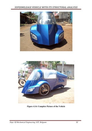
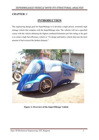
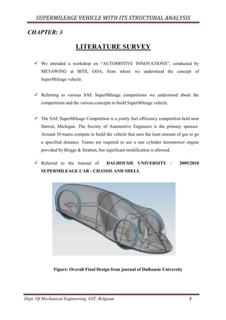
The document describes the design of a supermileage vehicle. It discusses the goals of developing a high fuel efficiency vehicle. The vehicle will use a Honda GK 100 97 cc 4-stroke engine with a CVT pulley-based transmission. The chassis will be a space frame constructed of 1.5mm thick mild steel pipes. Other components include a twin tie rod steering mechanism, 15-inch low rolling resistance tires, bicycle brakes, and batteries to power electrical systems. Structural analysis was performed to test the chassis' ability to withstand front and side impact loads up to 7291N and 4375N respectively. The chassis design and component selection were aimed at minimizing weight while maintaining safety.
![SUPERMILEAGE VEHICLE WITH ITS STRUCTURAL ANALYSIS
Dept. Of Mechanical Engineering, GIT, Belgaum 2
CHAPTER: 2
PROJECT DESCRIPTION
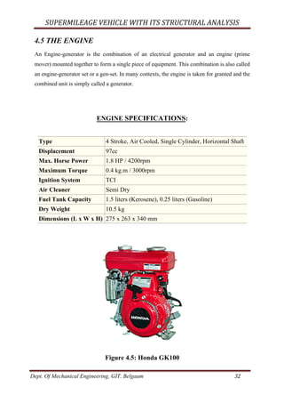
2.1 Engine and Power train:
The engine to be used is Honda GK 100 97 cc. The engine is 4 strokes, Air Cooled, Single
Cylinder, and Horizontal Shaft, with a 1.3 kW @ 4,200 rpm.
2. 2 Transmission: CVT [Pulley Based CVT]
Unlike traditional automatic transmissions, continuously variable transmissions don't have a
gearbox with a set number of gears, which means they don't have interlocking toothed
wheels. The most common type of CVT operates on an ingenious pulley system that allows
an infinite variability between highest and lowest gears with no discrete steps or shifts
2.3 Steering:
The vehicle will feature “twin tie rod” mechanism, which takes a radius of 17 feet.
2.4 Chassis:
Chassis design is space frame, fabricated using 20 mm square & round MS Pipe of thickness
1.5mm.
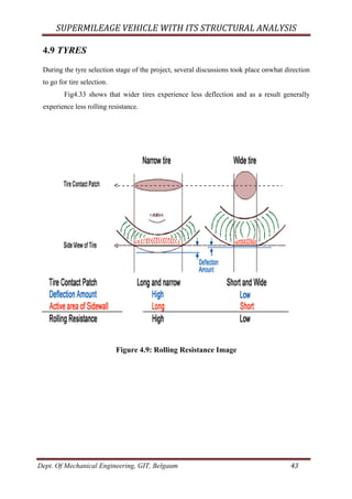
2.5 Tyres:
The tires are of size 15inch diameter, puncture resistant, lightweight, low rolling friction and
will feature silica energy rubber mix to ensure excellent grip and will feature more tread to
maximize the propulsion and minimize the slip.
2.6 Hub:
Hub is made of casted Aluminium with dimensions:
Outer Diameter – 80mm
Inner Diameter – 58mm
Length – 74mm
.](https://image.slidesharecdn.com/fc3e234e-04fa-46df-b7d2-f52f72c8a501-160121055850/85/Final-report-SMV-2-320.jpg)


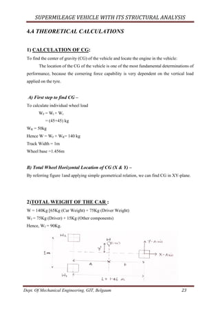
![SUPERMILEAGE VEHICLE WITH ITS STRUCTURAL ANALYSIS
Dept. Of Mechanical Engineering, GIT, Belgaum 24
Figure 4.4.(1): Horizontal Location of CG
By geometry,
ð W * b = Wf * L
b = Wf * L / W
b = 90 * 1.46 / 140
b = 0.94m.
Hence, a = 0.52m (Because L = a + b)
By geometry,
= >y’ = [W2 / W * (Tf – d)] – [W1/W * (d)]
d = 1m/2
d =0.5m
Hence,
y’ = [45(Kg) / 140(Kg)] * 0.5m - [45(Kg) / 140(Kg)]
y’ = 0
Normally in three wheel y’ = 0. i.e. its center line.
Figure 4.4.(2): Location of CG
3) Total Vehicle Vertical Location of CG can be practically determined:
Jack the rare axle up so that it forms some angle (450
) with the horizontal as shown:By basic
geometry, we can apply the geometry relation to find out the CG as shown in fig 4.4.3.](https://image.slidesharecdn.com/fc3e234e-04fa-46df-b7d2-f52f72c8a501-160121055850/85/Final-report-SMV-24-320.jpg)
![SUPERMILEAGE VEHICLE WITH ITS STRUCTURAL ANALYSIS
Dept. Of Mechanical Engineering, GIT, Belgaum 25
Figure 4.4.(3): Vertical Location of CG
ð L1 = Lcosθ
L1 = 1.46 cos450
[Maximum Angle Raised for CG]
L1 = 1.032m
Taking moment about ‘O’
WfL1 = Wb1
ð b1 = WfL1 / W
b1 = 90 * 1.032 / 140
b1 = 0.66m.
By geometry,
W tanθ * h1 = Wf*L – W * b
• h1 = [Wf*L – W * b] / W tanθ
= [90 * 1.46 – 140 * 0.94] / 140 tan 450
= 0.2 / 140
h1 = 1.428 * 10-3
m
h1 = 1.428 mm
Let,
h = Loaded radius of wheel + h1
= [7”
= 175mm] from ground
= 175 + 1.428
h = 176.428 mm from ground](https://image.slidesharecdn.com/fc3e234e-04fa-46df-b7d2-f52f72c8a501-160121055850/85/Final-report-SMV-25-320.jpg)

![SUPERMILEAGE VEHICLE WITH ITS STRUCTURAL ANALYSIS
Dept. Of Mechanical Engineering, GIT, Belgaum 27
Weight transfer due to cornering force is given by the relation,
ΔW = WL- Wt / 2
= WAy h / t
Ay = A / B
= 50 (lbs) / 45 (lbs)
Ay = 1.11
ΔWL = 140(kg) * 1.11* 357.42(mm) / 1460(mm)
ΔWL = 38.61
This extra force on the wheel while cornering [i.e. inner wheel].
2) Longitudinal Weight Transfer:
During Acceleration or Braking, Inertial Force is developed that is similar to the Centrifugal
Force.
Fig 4.4.(6): Longitudinal Weight Transfer
Taking moment about pt ‘O’.
ΔWLo= (h / l) * W * Ay
= (357.42 / 1460) * 140 * 1.11 [same procedure]
= 38.61 kg
ΔWLo= 380N (Because 38.61* 9.81)](https://image.slidesharecdn.com/fc3e234e-04fa-46df-b7d2-f52f72c8a501-160121055850/85/Final-report-SMV-27-320.jpg)
![SUPERMILEAGE VEHICLE WITH ITS STRUCTURAL ANALYSIS
Dept. Of Mechanical Engineering, GIT, Belgaum 28
3) Static Force:
Since total weight, W = Wf + WR
= 90(kg) + 50(kg)
W = 140(kg)
The calculation is same as done to find out the C.G.
4) Dynamic Force:
Dynamic force is 0.6 to 0.8 times the static force for more FOS. Hence we take double the
static force.
Therefore maximum load on each wheel is = Sum of [static load (w) + dynamic load (Wd) +
lateral load due to lateral load transfer (ΔWL) + Longitudinal load due to long loading
transfer (ΔWLo)]
Therefore load on front perpendicular wheel can be calculated as,
Weight Ratio taken as,
= 60:40 (F: R) (because of loading)
• Wf = 0.6 * 140
= 84 N, on each Wheel
1. For single wheel= 420N
2. Dynamic = 420N (same as it)
3. Lateral = 370N
4. Longitudinal = 380N
Hence, Wt= 1590N](https://image.slidesharecdn.com/fc3e234e-04fa-46df-b7d2-f52f72c8a501-160121055850/85/Final-report-SMV-28-320.jpg)
![SUPERMILEAGE VEHICLE WITH ITS STRUCTURAL ANALYSIS
Dept. Of Mechanical Engineering, GIT, Belgaum 29
Fig 4.4.(7): Forces Acting on Square Pipe
Then,
• F’
* 0.3= 1590*0.5
• F’
= 2650N [maximum force produced at element ‘E’]
If we design for that maximum load on this (round) pipe, and we can keep the same
dimension for the other (square) pipe too.
Now if we analyze this vertical (square) pipe it acts like column with both ends fixed.](https://image.slidesharecdn.com/fc3e234e-04fa-46df-b7d2-f52f72c8a501-160121055850/85/Final-report-SMV-29-320.jpg)
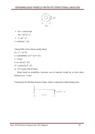
![SUPERMILEAGE VEHICLE WITH ITS STRUCTURAL ANALYSIS
Dept. Of Mechanical Engineering, GIT, Belgaum 31
(If not full force transfer, it part of 1590N we take 1590N for safety)
σb = (MI) / Y [for mild steel σb = 310MPa]
310 (MPa) = M/Z (also Z= (π / 64) (do
4
– di
4
) / (d / 2)
Z= (π / 32) [(do
4
– di
4
) / do])
Z= M / 310
= (1590 * 250) /310
= 1204.5mm3
Z = (1204.5 * 32) / π= (do
4
– di
4
) / do
= 12269.3 = (do
4
– di
4
) / do
do = 20mm (taken)
And also is sufficient based on availability, cost, weight etc.
Not any part of chassis is going to subject stresses more than σy = 310MPa
For FOS = 3
Hence we fix t =1.5mm
do= 20mm.](https://image.slidesharecdn.com/fc3e234e-04fa-46df-b7d2-f52f72c8a501-160121055850/85/Final-report-SMV-31-320.jpg)