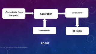
IMAGE RECOGNITION AND REAL TIME
PATH FINDING ROBOT
by
Sujai V. Nair
Urvil P. Parmar
Akash B. Mande
Pankaj S. Nakhale
Guided by
Mrs. P. N. Savagave
INTRODUCTION
• Motivation
Integration of obstacle avoider with a path finding algorithm and image recognition to help a
robot reach its destination with only the top view photograph of the path.
• Image recognition
The process of identifying and detecting an object or a feature in a digital image
• Advantages of proposed project
• Real time co-ordinates are calculated automatically.
• Physical measurements are avoided.
• Robot is completely autonomous.
• Can be used as a basis for automation in industrial goods transport.
• Added intelligence to robot can allow canvasing of areas inaccessible to human beings.
• Satellite images can be used for drone airplanes and rovers.
2Image Recognition and Real Time Path Finding Robot
STAGES OF PROJECT
• Identifying suitable sensors for the robot
• Making an obstacle avoiding robot
• Taking sample images for recognition
• Finding physical co-ordinates from image
• Determining path for robot
• Integration of above stages
3Image Recognition and Real Time Path Finding Robot
BLOCK DIAGRAMS
OUR PROJECT
Image Computer BOT
4Image Recognition and Real Time Path Finding Robot
ROBOT
Co-ordinate from
computer
Controller Motor driver
TSOP sensor DC motor
5Image Recognition and Real Time Path Finding Robot
INTERFACING
TSOP sensor
Motor driver L293D12 V power supply
ATMEGA32 microcontroller 200 RPM DC MotorImage Processing
6Image Recognition and Real Time Path Finding Robot
HARDWARE DESCRIPTION
• 200 RPM Centre Shaft Economy Series DC Motor
• Position Encoder Kit
• Single TSOP Sensor module
• L293D Motor Driver
• ATMEGA32 Development Board
7Image Recognition and Real Time Path Finding Robot
200 RPM Centre Shaft Economy Series DC Motor
• 200RPM Centre Shaft Economy Series DC Motor is high quality low cost DC
geared motor. It has steel gears and pinions to ensure longer life and better
wear and tear properties.
• Motor gives 200 RPM at 12V but motor runs smoothly from 4V to 12V and
gives wide range of RPM, and torque
• Specifications
- DC supply: 4 to 12V
- RPM: 200 at 12V
- Brush type: Precious metal
- Output shaft: Centred
- Gear assembly: Spur
- Motor weight: 90gms
8Image Recognition and Real Time Path Finding Robot
Position Encoder Kit
• Position Encoder Kit is used to measure speed of motor,
find out distance travelled by robot.
• Kit contents
1-Universal wheel
1-Encoder Disc
1-Motor Mount
1-Encoder Mount
2-12mm star bolt for Motor mount
2-8mm star bolt for Encoder
2-5mm self threading screw for metal disc
1-6.5mm self threading screw for universal wheel
4-M3 Nut
2-Spring washers
• Specification
• Position Encoder with RA Mount
• Encoder resolution: 5.44mm / pulse
9Image Recognition and Real Time Path Finding Robot
Single TSOP sensor module
• The module consists of 555 IC, working in astable multi vibrator configuration.
• The output of TSOP is high whenever it receives a fixed frequency and low otherwise.
• The on-board LED indicator helps user to check status of the sensor without using any additional
hardware.
• It gives a digital output and false detection due ambient light is low.
• Features
• Allows your robot to detect obstacles.
• Typical Maximum Range: 20 cm.
• Modulated IR transmitter to avoid any interferences
• Calibration preset for range adjustment.
• Indicator LED with 3 pin easy interface connector.
10Image Recognition and Real Time Path Finding Robot
L293D Motor Driver
• The L293D is a Dual Full Bridge driver that can drive up to 1 Amp per bridge with supply voltage up to
24V.
• It can drive two DC motors in both direction and 4 DC motor in single direction, relays, solenoids, etc.
• The device is TTL compatible.
• Specifications
• Operating supply voltage up to 24 volts
• It can drive bipolar stepper motor up to 1 Amp.
• Bidirectional control of 2 DC motors up to 1 amp each
• Operating PWM frequency range up to 20 KHz
• Current sensing output
• Over temperature protection
11Image Recognition and Real Time Path Finding Robot
ATMEGA32 Development Board
• High-performance, Low-power AVR® 8-bit Microcontroller
• Advanced RISC Architecture
• Non-volatile Program and Data Memories
• JTAG (IEEE std. 1149.1 Compliant) Interface
• Peripheral Features
• Special Microcontroller Features
• I/O and Packages
• Operating Voltages
• Speed Grades
• Power Consumption at 1 MHz, 3V, 25°C for ATmega32L
12Image Recognition and Real Time Path Finding Robot
SOFTWARE USED
• MATLAB
• AVR Studio4
13Image Recognition and Real Time Path Finding Robot
IMAGE RECOGNITION
14Image Recognition and Real Time Path Finding Robot
Captured Image Edited Image
CALCULATIONS
• Real Time calculations by robot
• Calculations in MATLAB
15Image Recognition and Real Time Path Finding Robot
Real time calculation by Robot
16Image Recognition and Real Time Path Finding Robot
17Image Recognition and Real Time Path Finding Robot
Quadrant Left turn Right turn
I
Turn with angle (90-Ɵ)
y = Y - y` - Dist
x = X - x`
turn right with (90- Ɵ`)
Turn with angle Ɵ
y = Y – y`
x = X- x`- Dist
turn left with Ɵ`
II
Turn with angle Ɵ
y = Y - y`
x = X - x` -Dist
turn right with Ɵ`
Turn with angle (90-Ɵ)
y = Y – y`- Dist
x = X- x`
turn left with (90-Ɵ`)
III
Turn with angle (90-Ɵ)
y = Y - y` - Dist
x = X - x`
turn right with (90- Ɵ`)
Turn with angle Ɵ
y = Y – y`
x = X- x`- Dist
turn left with Ɵ`
IV
Turn with angle Ɵ
y = Y - y`
x = X - x`- Dist
turn right with Ɵ`
Turn with angle (90-Ɵ)
y = Y – y`- Dist
x = X- x`
turn left with (90-Ɵ`)
18Image Recognition and Real Time Path Finding Robot
1st Quadrant 2nd Quadrant
19Image Recognition and Real Time Path Finding Robot
3rd Quadrant 4th Quadrant
20Image Recognition and Real Time Path Finding Robot
ERRORS
• In Image Capturing
• In MATLAB
• In hardware
• Motors
• Wheels
21Image Recognition and Real Time Path Finding Robot
CORRECTIONS
• During angle measurement
• During Distance measurement
• For projection in image
22Image Recognition and Real Time Path Finding Robot
LIMITATIONS
• Resolution of encoder
• Wheel
• Wheel Diameter
• Wheel Grips
• Motors
• Software
23Image Recognition and Real Time Path Finding Robot
DEMO
• Video demonstration
24Image Recognition and Real Time Path Finding Robot
BIBLOGRAPHY
• www.campuscomponent.com
• www.alldatasheets.com
• www.mathworks.in
• en.wikipedia.org
• www.nex-robotics.com
• www.atmel.in
• Digital Image Processing …third edition
by Rafael C. Gonzalez and Richard E. Woods
25Image Recognition and Real Time Path Finding Robot
THANK YOU…

Final Presentation COMPRESSED

  • 1.
    IMAGE RECOGNITION ANDREAL TIME PATH FINDING ROBOT by Sujai V. Nair Urvil P. Parmar Akash B. Mande Pankaj S. Nakhale Guided by Mrs. P. N. Savagave
  • 2.
    INTRODUCTION • Motivation Integration ofobstacle avoider with a path finding algorithm and image recognition to help a robot reach its destination with only the top view photograph of the path. • Image recognition The process of identifying and detecting an object or a feature in a digital image • Advantages of proposed project • Real time co-ordinates are calculated automatically. • Physical measurements are avoided. • Robot is completely autonomous. • Can be used as a basis for automation in industrial goods transport. • Added intelligence to robot can allow canvasing of areas inaccessible to human beings. • Satellite images can be used for drone airplanes and rovers. 2Image Recognition and Real Time Path Finding Robot
  • 3.
    STAGES OF PROJECT •Identifying suitable sensors for the robot • Making an obstacle avoiding robot • Taking sample images for recognition • Finding physical co-ordinates from image • Determining path for robot • Integration of above stages 3Image Recognition and Real Time Path Finding Robot
  • 4.
    BLOCK DIAGRAMS OUR PROJECT ImageComputer BOT 4Image Recognition and Real Time Path Finding Robot
  • 5.
    ROBOT Co-ordinate from computer Controller Motordriver TSOP sensor DC motor 5Image Recognition and Real Time Path Finding Robot
  • 6.
    INTERFACING TSOP sensor Motor driverL293D12 V power supply ATMEGA32 microcontroller 200 RPM DC MotorImage Processing 6Image Recognition and Real Time Path Finding Robot
  • 7.
    HARDWARE DESCRIPTION • 200RPM Centre Shaft Economy Series DC Motor • Position Encoder Kit • Single TSOP Sensor module • L293D Motor Driver • ATMEGA32 Development Board 7Image Recognition and Real Time Path Finding Robot
  • 8.
    200 RPM CentreShaft Economy Series DC Motor • 200RPM Centre Shaft Economy Series DC Motor is high quality low cost DC geared motor. It has steel gears and pinions to ensure longer life and better wear and tear properties. • Motor gives 200 RPM at 12V but motor runs smoothly from 4V to 12V and gives wide range of RPM, and torque • Specifications - DC supply: 4 to 12V - RPM: 200 at 12V - Brush type: Precious metal - Output shaft: Centred - Gear assembly: Spur - Motor weight: 90gms 8Image Recognition and Real Time Path Finding Robot
  • 9.
    Position Encoder Kit •Position Encoder Kit is used to measure speed of motor, find out distance travelled by robot. • Kit contents 1-Universal wheel 1-Encoder Disc 1-Motor Mount 1-Encoder Mount 2-12mm star bolt for Motor mount 2-8mm star bolt for Encoder 2-5mm self threading screw for metal disc 1-6.5mm self threading screw for universal wheel 4-M3 Nut 2-Spring washers • Specification • Position Encoder with RA Mount • Encoder resolution: 5.44mm / pulse 9Image Recognition and Real Time Path Finding Robot
  • 10.
    Single TSOP sensormodule • The module consists of 555 IC, working in astable multi vibrator configuration. • The output of TSOP is high whenever it receives a fixed frequency and low otherwise. • The on-board LED indicator helps user to check status of the sensor without using any additional hardware. • It gives a digital output and false detection due ambient light is low. • Features • Allows your robot to detect obstacles. • Typical Maximum Range: 20 cm. • Modulated IR transmitter to avoid any interferences • Calibration preset for range adjustment. • Indicator LED with 3 pin easy interface connector. 10Image Recognition and Real Time Path Finding Robot
  • 11.
    L293D Motor Driver •The L293D is a Dual Full Bridge driver that can drive up to 1 Amp per bridge with supply voltage up to 24V. • It can drive two DC motors in both direction and 4 DC motor in single direction, relays, solenoids, etc. • The device is TTL compatible. • Specifications • Operating supply voltage up to 24 volts • It can drive bipolar stepper motor up to 1 Amp. • Bidirectional control of 2 DC motors up to 1 amp each • Operating PWM frequency range up to 20 KHz • Current sensing output • Over temperature protection 11Image Recognition and Real Time Path Finding Robot
  • 12.
    ATMEGA32 Development Board •High-performance, Low-power AVR® 8-bit Microcontroller • Advanced RISC Architecture • Non-volatile Program and Data Memories • JTAG (IEEE std. 1149.1 Compliant) Interface • Peripheral Features • Special Microcontroller Features • I/O and Packages • Operating Voltages • Speed Grades • Power Consumption at 1 MHz, 3V, 25°C for ATmega32L 12Image Recognition and Real Time Path Finding Robot
  • 13.
    SOFTWARE USED • MATLAB •AVR Studio4 13Image Recognition and Real Time Path Finding Robot
  • 14.
    IMAGE RECOGNITION 14Image Recognitionand Real Time Path Finding Robot Captured Image Edited Image
  • 15.
    CALCULATIONS • Real Timecalculations by robot • Calculations in MATLAB 15Image Recognition and Real Time Path Finding Robot
  • 16.
    Real time calculationby Robot 16Image Recognition and Real Time Path Finding Robot
  • 17.
    17Image Recognition andReal Time Path Finding Robot
  • 18.
    Quadrant Left turnRight turn I Turn with angle (90-Ɵ) y = Y - y` - Dist x = X - x` turn right with (90- Ɵ`) Turn with angle Ɵ y = Y – y` x = X- x`- Dist turn left with Ɵ` II Turn with angle Ɵ y = Y - y` x = X - x` -Dist turn right with Ɵ` Turn with angle (90-Ɵ) y = Y – y`- Dist x = X- x` turn left with (90-Ɵ`) III Turn with angle (90-Ɵ) y = Y - y` - Dist x = X - x` turn right with (90- Ɵ`) Turn with angle Ɵ y = Y – y` x = X- x`- Dist turn left with Ɵ` IV Turn with angle Ɵ y = Y - y` x = X - x`- Dist turn right with Ɵ` Turn with angle (90-Ɵ) y = Y – y`- Dist x = X- x` turn left with (90-Ɵ`) 18Image Recognition and Real Time Path Finding Robot
  • 19.
    1st Quadrant 2ndQuadrant 19Image Recognition and Real Time Path Finding Robot
  • 20.
    3rd Quadrant 4thQuadrant 20Image Recognition and Real Time Path Finding Robot
  • 21.
    ERRORS • In ImageCapturing • In MATLAB • In hardware • Motors • Wheels 21Image Recognition and Real Time Path Finding Robot
  • 22.
    CORRECTIONS • During anglemeasurement • During Distance measurement • For projection in image 22Image Recognition and Real Time Path Finding Robot
  • 23.
    LIMITATIONS • Resolution ofencoder • Wheel • Wheel Diameter • Wheel Grips • Motors • Software 23Image Recognition and Real Time Path Finding Robot
  • 24.
    DEMO • Video demonstration 24ImageRecognition and Real Time Path Finding Robot
  • 25.
    BIBLOGRAPHY • www.campuscomponent.com • www.alldatasheets.com •www.mathworks.in • en.wikipedia.org • www.nex-robotics.com • www.atmel.in • Digital Image Processing …third edition by Rafael C. Gonzalez and Richard E. Woods 25Image Recognition and Real Time Path Finding Robot
  • 26.