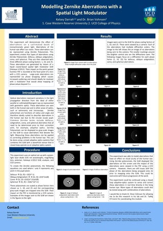
Modelling	
  Zernike	
  AberraFons	
  with	
  a	
  
SpaFal	
  Light	
  Modulator	
  
Kelsey	
  Darrah1,2	
  and	
  Dr.	
  Brian	
  Vohnsen2	
  
1.	
  Case	
  Western	
  Reserve	
  University	
  2.	
  UCD	
  College	
  of	
  Physics	
  
Kelsey	
  Darrah	
  
Case	
  Western	
  Reserve	
  University	
  
Email:	
  kmd122@case.edu	
  
Contact	
  
1.  Jewel,	
  A.	
  R.,	
  V.	
  Akondi,	
  and	
  B.	
  Vohnsen.	
  "A	
  Direct	
  Comparison	
  between	
  a	
  MEMS	
  Deformable	
  Mirror	
  and	
  a	
  Liquid	
  Crystal	
  
Spa7al	
  Light	
  Modulator	
  in	
  Signal-­‐based	
  Wavefront	
  Sensing."	
  JEOS:RP	
  Journal	
  of	
  the	
  European	
  Op7cal	
  Society:	
  Rapid	
  
Publica7ons	
  8	
  (2013):	
  n.	
  pag.	
  Web.	
  	
  
2.  Liang*,	
  Junzhong,	
  Bernhard	
  Grimm,	
  Stefan	
  Goelz,	
  and	
  Josef	
  F.	
  Bille.	
  "Objec7ve	
  Measurement	
  of	
  Wave	
  Aberra7ons	
  of	
  the	
  
Human	
  Eye	
  with	
  the	
  Use	
  of	
  a	
  Hartmann-­‐Shack	
  Wave-­‐front	
  Sensor."	
  Journal	
  of	
  the	
  Op7cal	
  Society	
  of	
  America	
  A	
  J.	
  Opt.	
  Soc.	
  
Am.	
  A	
  11.7	
  (1994):	
  1949.	
  Web.	
  
References	
  
This	
   experiment	
   will	
   demonstrate	
   the	
   effect	
   of	
  
aberra7ons	
   on	
   a	
   collimated	
   beam	
   of	
  
monochroma7c	
   green	
   light.	
   Aberra7ons	
   of	
   the	
  
human	
  eye	
  effect	
  our	
  vision.	
  These	
  aberra7ons	
  can	
  
be	
   represented	
   using	
   Zernike	
   Polynomials.	
   This	
  
experiment	
  creates	
  four	
  types	
  of	
  aberra7ons	
  using	
  
Zernike	
  Polynomials:	
  defocus,	
  oblique	
  as7gma7sm,	
  
coma,	
  and	
  spherical.	
  They	
  are	
  then	
  observed	
  with	
  
three	
  different	
  phase	
  scaling	
  factors:	
  1,	
  10,	
  and	
  25.	
  	
  
These	
   aberra7ons	
   are	
   generated	
   by	
   means	
   of	
   a	
  
liquid	
   crystal-­‐based	
   spa7al	
   light	
   modulator	
   SLM	
  
(Holoeye	
  LC2012).	
  Their	
  impact	
  on	
  the	
  point-­‐spread	
  
func7on	
  PSF	
  is	
  recorded	
  at	
  the	
  focal	
  point	
  of	
  a	
  lens	
  
with	
   a	
   CCD	
   camera.	
   	
   Large-­‐scale	
   aberra7ons	
   are	
  
represented	
   via	
   phase	
   wrapping	
   which	
   causes	
  
increased	
  scavering	
  and	
  should	
  ideally	
  be	
  resolved	
  
with	
   a	
   modulator	
   that	
   would	
   allow	
   mapping	
   of	
  
phase	
  values	
  beyond	
  2 π.	
  
Abstract	
  
Images	
  were	
  sent	
  to	
  the	
  SLM	
  for	
  phase	
  scaling	
  factors	
  of	
  
1,	
  10,	
  and	
  25.	
  These	
  were	
  viewed	
  by	
  a	
  camera.	
  Each	
  of	
  
the	
   aberra7ons	
   had	
   mul7ple	
   diffrac7on	
   orders.	
   The	
  
image	
  to	
  the	
  leN	
  shows	
  the	
  an	
  image	
  of	
  no	
  aberra7ons	
  
being	
  sent	
  to	
  the	
  camera.	
  The	
  smaller	
  markings	
  around	
  
the	
   brighter	
   central	
   one	
   are	
   the	
   diffrac7ons	
   seen.	
   The	
  
following	
   images	
   focus	
   on	
   a	
   diffrac7on	
   for	
   each	
   phase	
  
factor	
   (1,	
   10,	
   25)	
   for	
   defocus,	
   oblique	
   as7gma7sm,	
  
coma,	
  and	
  spherical	
  aberra7ons.	
  
IntroducFon	
  
Op7cal	
  aberra7ons	
  represent	
  varia7ons	
  in	
  the	
  light	
  
propaga7on	
   direc7on	
   from	
   the	
   ideal	
   of	
   either	
  
parallel	
  or	
  collimated/divergent	
  rays	
  as	
  represented	
  
with	
  geometric	
  op7cs.	
  These	
  aberra7ons	
  are	
  seen	
  
both	
  in	
  the	
  human	
  eye	
  and	
  in	
  other	
  areas	
  of	
  op7cs,	
  
such	
   as	
   astronomy	
   and	
   microscopy.	
   	
   Zernike	
  
polynomials	
  are	
  func7ons	
  of	
  radius	
  and	
  angle	
  and	
  
therefore	
   ideally	
   suited	
   to	
   describe	
   aberra7ons	
   in	
  
the	
   human	
   eye	
   due	
   to	
   the	
   circular	
   ocular	
   pupil.	
  
Common	
   Zernike	
   terms	
   include	
   defocus,	
  
as7gma7sm,	
  coma,	
  and	
  spherical	
  aberra7on	
  that	
  all	
  
need	
   to	
   be	
   determined	
   prior	
   to	
   their	
   correc7on	
  
with,	
   for	
   example,	
   adap7ve	
   op7cs.	
   Zernike	
  
Polynomials	
  can	
  be	
  displayed	
  as	
  gray-­‐scale	
  images	
  
on	
   the	
   SLM	
   to	
   cause	
   aberra7ons	
   that	
   deviate	
   the	
  
light.	
   Measuring	
   these	
   aberra7ons	
   can	
   be	
   applied	
  
to	
  correc7ng	
  problems	
  in	
  the	
  human	
  eye.	
  This	
  can	
  
be	
  done	
  using	
  a	
  simple	
  adap7ve	
  op7cs	
  systems	
  that	
  
combines	
  the	
  SLM	
  with	
  a	
  wavefront	
  sensor	
  that	
  in	
  
closed	
  loop	
  operate	
  as	
  an	
  adap7ve	
  op7cs	
  system.	
  
Results	
  
Procedure	
  
This	
  experiment	
  uses	
  an	
  op7cal	
  set	
  up	
  with	
  a	
  green-­‐
light	
  laser	
  diode	
  (535	
  nm	
  wavelength),	
  magnifying	
  
lens,	
  polarizer,	
  Holoeye	
  LC2012	
  SLM,	
  analyzer,	
  and	
  
CCD	
  camera.	


To	
   create	
   the	
   Zernike	
   polynomials,	
   the	
   following	
  
equa7ons	
   are	
   used	
   where	
   r	
   and	
   θ	
   represents	
   any	
  
point	
  in	
  the	
  pupil	
  plane:	


Defocus	
  à	
  Z(r,	
  θ)	
  =	
  √3(2r2-­‐1)	
  	
  
Oblique	
  As7gma7sm	
  à	
  à	
  Z(r,	
  Θ)	
  =2√3r2sin(θ)	
  
Coma	
  à	
  Z(r,	
  Θ)	
  =2√2(3r3-­‐2r)sin(θ)	
  
Spherical	
  à	
  Z(r,	
  θ)	
  =	
  √5(6r4-­‐6r2+1)	


These	
  polynomials	
  are	
  scaled	
  as	
  phase	
  factors	
  here	
  
chosen	
   as	
   1,	
   10,	
   and	
   25	
   and	
   the	
   corresponding	
  
grey-­‐scale	
  images	
  are	
  mapped	
  onto	
  the	
  SLM.	
  Their	
  
impact	
  on	
  the	
  PSF	
  is	
  monitored	
  by	
  a	
  CCD	
  camera.	
  
Examples	
  of	
  the	
  images	
  sent	
  to	
  the	
  SLM	
  are	
  shown	
  
in	
  the	
  figures	
  to	
  the	
  right.	
  
This	
  experiment	
  was	
  able	
  to	
  model	
  aberra7ons	
  that	
  
have	
  an	
  effect	
  on	
  visual	
  acuity	
  of	
  the	
  human	
  eye.	
  
Using	
   Zernike	
   polynomials,	
   the	
   SLM	
   displayed	
   the	
  
aberra7ons	
   on	
   the	
   screen	
   and	
   the	
   impact	
   of	
   the	
  	
  
aberra7ons	
   were	
   viewed	
   in	
   the	
   PSF	
   using	
   a	
   CCD	
  
camera.	
   	
   However,	
   there	
   are	
   s7ll	
   issues	
   with	
   the	
  
phase	
   of	
   the	
   aberra7ons	
   being	
   wrapped	
   onto	
   2π	
  
prior	
   to	
   mapping	
   onto	
   the	
   SLM.	
   This	
   could	
   be	
  
overcome	
  with	
  future	
  progression	
  of	
  the	
  work.	


This	
  experiment	
  could	
  be	
  con7nued	
  using	
  a	
  closed	
  
loop	
   adap7ve-­‐op7cs	
   system	
   to	
   sense	
   and	
   correct	
  
these	
  aberra7ons	
  in	
  real	
  7me	
  directly	
  in	
  the	
  living	
  
human	
   eye.	
   More	
   types	
   of	
   aberra7ons	
   could	
   also	
  
be	
  tested	
  along	
  with	
  combina7ons	
  of	
  aberra7ons.	


I	
  would	
  like	
  to	
  thank	
  Dr.	
  Brian	
  Vohnsen	
  for	
  allowing	
  
me	
   to	
   do	
   this	
   research	
   in	
   his	
   lab	
   and	
   Dr.	
   Tadhg	
  
O’Croinin	
  for	
  coordina7ng	
  this	
  module.	
  
Figure	
  1:	
  image	
  of	
  coma	
  aberra7on	
   Figure	
  2:	
  image	
  of	
  defocus	
  aberra7on	
  
Figure	
  3:	
  image	
  of	
  oblique	
  	
  
as7gma7sm	
  aberra7on	
  (with	
  
phase	
  scaling	
  factor	
  =	
  10)	
  
Figure	
  4:	
  image	
  of	
  
spherical	
  aberra7on	
  (with	
  
phase	
  scaling	
  factor	
  =	
  10)	
  
Conclusions	
  
Figure	
  5:	
  image	
  from	
  camera	
  with	
  no	
  aberra7ons	
  
show	
  mul7ple	
  diffrac7on	
  orders	
  from	
  the	
  SLM	
  
Figures	
  6-­‐8:	
  
image	
  from	
  
camera	
  with	
  
defocus	
  
aberra7ons	
  
with	
  phase	
  
factor	
  =	
  1,	
  10,	
  
25	
  (leN	
  to	
  
right)	
  
Figure	
  6	
  	
   Figure	
  7	
  	
   Figure	
  8	
  
Figure	
  9	
  	
   Figure	
  10	
  	
   Figure	
  11	
  	
  
Figure	
  12	
  	
   Figure	
  13	
  	
   Figure	
  14	
  	
  
Figure	
  15	
  	
   Figure	
  16	
  	
   Figure	
  17	
  	
  
Figures	
  15-­‐17:	
  
image	
  from	
  
camera	
  with	
  
defocus	
  
aberra7ons	
  
with	
  phase	
  
factor	
  =	
  1,	
  10,	
  
25	
  (leN	
  to	
  
right)	
  
Figures	
  9-­‐11:	
  
image	
  from	
  
camera	
  with	
  
as7gma7sm	
  
aberra7ons	
  
with	
  phase	
  
factor	
  =	
  1,	
  10,	
  
25	
  (leN	
  to	
  
right)	
  
Figures	
  12-­‐14:	
  
image	
  from	
  
camera	
  with	
  
coma	
  	
  
aberra7ons	
  
with	
  phase	
  
factor	
  =	
  1,	
  10,	
  
25	
  (leN	
  to	
  
right)	
  

final poster Kelsey

  • 1.
    Modelling  Zernike  AberraFons  with  a   SpaFal  Light  Modulator   Kelsey  Darrah1,2  and  Dr.  Brian  Vohnsen2   1.  Case  Western  Reserve  University  2.  UCD  College  of  Physics   Kelsey  Darrah   Case  Western  Reserve  University   Email:  kmd122@case.edu   Contact   1.  Jewel,  A.  R.,  V.  Akondi,  and  B.  Vohnsen.  "A  Direct  Comparison  between  a  MEMS  Deformable  Mirror  and  a  Liquid  Crystal   Spa7al  Light  Modulator  in  Signal-­‐based  Wavefront  Sensing."  JEOS:RP  Journal  of  the  European  Op7cal  Society:  Rapid   Publica7ons  8  (2013):  n.  pag.  Web.     2.  Liang*,  Junzhong,  Bernhard  Grimm,  Stefan  Goelz,  and  Josef  F.  Bille.  "Objec7ve  Measurement  of  Wave  Aberra7ons  of  the   Human  Eye  with  the  Use  of  a  Hartmann-­‐Shack  Wave-­‐front  Sensor."  Journal  of  the  Op7cal  Society  of  America  A  J.  Opt.  Soc.   Am.  A  11.7  (1994):  1949.  Web.   References   This   experiment   will   demonstrate   the   effect   of   aberra7ons   on   a   collimated   beam   of   monochroma7c   green   light.   Aberra7ons   of   the   human  eye  effect  our  vision.  These  aberra7ons  can   be   represented   using   Zernike   Polynomials.   This   experiment  creates  four  types  of  aberra7ons  using   Zernike  Polynomials:  defocus,  oblique  as7gma7sm,   coma,  and  spherical.  They  are  then  observed  with   three  different  phase  scaling  factors:  1,  10,  and  25.     These   aberra7ons   are   generated   by   means   of   a   liquid   crystal-­‐based   spa7al   light   modulator   SLM   (Holoeye  LC2012).  Their  impact  on  the  point-­‐spread   func7on  PSF  is  recorded  at  the  focal  point  of  a  lens   with   a   CCD   camera.     Large-­‐scale   aberra7ons   are   represented   via   phase   wrapping   which   causes   increased  scavering  and  should  ideally  be  resolved   with   a   modulator   that   would   allow   mapping   of   phase  values  beyond  2 π.   Abstract   Images  were  sent  to  the  SLM  for  phase  scaling  factors  of   1,  10,  and  25.  These  were  viewed  by  a  camera.  Each  of   the   aberra7ons   had   mul7ple   diffrac7on   orders.   The   image  to  the  leN  shows  the  an  image  of  no  aberra7ons   being  sent  to  the  camera.  The  smaller  markings  around   the   brighter   central   one   are   the   diffrac7ons   seen.   The   following   images   focus   on   a   diffrac7on   for   each   phase   factor   (1,   10,   25)   for   defocus,   oblique   as7gma7sm,   coma,  and  spherical  aberra7ons.   IntroducFon   Op7cal  aberra7ons  represent  varia7ons  in  the  light   propaga7on   direc7on   from   the   ideal   of   either   parallel  or  collimated/divergent  rays  as  represented   with  geometric  op7cs.  These  aberra7ons  are  seen   both  in  the  human  eye  and  in  other  areas  of  op7cs,   such   as   astronomy   and   microscopy.     Zernike   polynomials  are  func7ons  of  radius  and  angle  and   therefore   ideally   suited   to   describe   aberra7ons   in   the   human   eye   due   to   the   circular   ocular   pupil.   Common   Zernike   terms   include   defocus,   as7gma7sm,  coma,  and  spherical  aberra7on  that  all   need   to   be   determined   prior   to   their   correc7on   with,   for   example,   adap7ve   op7cs.   Zernike   Polynomials  can  be  displayed  as  gray-­‐scale  images   on   the   SLM   to   cause   aberra7ons   that   deviate   the   light.   Measuring   these   aberra7ons   can   be   applied   to  correc7ng  problems  in  the  human  eye.  This  can   be  done  using  a  simple  adap7ve  op7cs  systems  that   combines  the  SLM  with  a  wavefront  sensor  that  in   closed  loop  operate  as  an  adap7ve  op7cs  system.   Results   Procedure   This  experiment  uses  an  op7cal  set  up  with  a  green-­‐ light  laser  diode  (535  nm  wavelength),  magnifying   lens,  polarizer,  Holoeye  LC2012  SLM,  analyzer,  and   CCD  camera.     To   create   the   Zernike   polynomials,   the   following   equa7ons   are   used   where   r   and   θ   represents   any   point  in  the  pupil  plane:     Defocus  à  Z(r,  θ)  =  √3(2r2-­‐1)     Oblique  As7gma7sm  à  à  Z(r,  Θ)  =2√3r2sin(θ)   Coma  à  Z(r,  Θ)  =2√2(3r3-­‐2r)sin(θ)   Spherical  à  Z(r,  θ)  =  √5(6r4-­‐6r2+1)       These  polynomials  are  scaled  as  phase  factors  here   chosen   as   1,   10,   and   25   and   the   corresponding   grey-­‐scale  images  are  mapped  onto  the  SLM.  Their   impact  on  the  PSF  is  monitored  by  a  CCD  camera.   Examples  of  the  images  sent  to  the  SLM  are  shown   in  the  figures  to  the  right.   This  experiment  was  able  to  model  aberra7ons  that   have  an  effect  on  visual  acuity  of  the  human  eye.   Using   Zernike   polynomials,   the   SLM   displayed   the   aberra7ons   on   the   screen   and   the   impact   of   the     aberra7ons   were   viewed   in   the   PSF   using   a   CCD   camera.     However,   there   are   s7ll   issues   with   the   phase   of   the   aberra7ons   being   wrapped   onto   2π   prior   to   mapping   onto   the   SLM.   This   could   be   overcome  with  future  progression  of  the  work.     This  experiment  could  be  con7nued  using  a  closed   loop   adap7ve-­‐op7cs   system   to   sense   and   correct   these  aberra7ons  in  real  7me  directly  in  the  living   human   eye.   More   types   of   aberra7ons   could   also   be  tested  along  with  combina7ons  of  aberra7ons.     I  would  like  to  thank  Dr.  Brian  Vohnsen  for  allowing   me   to   do   this   research   in   his   lab   and   Dr.   Tadhg   O’Croinin  for  coordina7ng  this  module.   Figure  1:  image  of  coma  aberra7on   Figure  2:  image  of  defocus  aberra7on   Figure  3:  image  of  oblique     as7gma7sm  aberra7on  (with   phase  scaling  factor  =  10)   Figure  4:  image  of   spherical  aberra7on  (with   phase  scaling  factor  =  10)   Conclusions   Figure  5:  image  from  camera  with  no  aberra7ons   show  mul7ple  diffrac7on  orders  from  the  SLM   Figures  6-­‐8:   image  from   camera  with   defocus   aberra7ons   with  phase   factor  =  1,  10,   25  (leN  to   right)   Figure  6     Figure  7     Figure  8   Figure  9     Figure  10     Figure  11     Figure  12     Figure  13     Figure  14     Figure  15     Figure  16     Figure  17     Figures  15-­‐17:   image  from   camera  with   defocus   aberra7ons   with  phase   factor  =  1,  10,   25  (leN  to   right)   Figures  9-­‐11:   image  from   camera  with   as7gma7sm   aberra7ons   with  phase   factor  =  1,  10,   25  (leN  to   right)   Figures  12-­‐14:   image  from   camera  with   coma     aberra7ons   with  phase   factor  =  1,  10,   25  (leN  to   right)