Download to read offline
![Page 4 of 8
Centroid and Moment of Inertia:
Centroid Location: 𝑥̅ = 1𝑖𝑛, 𝑦̅ = 2 𝑖𝑛 (by symmetry)
Moment of Inertia: 𝐼 =
1
12
[ 𝑏ℎ3] =
1
12
[(2𝑖𝑛)(4𝑖𝑛)3] = 5.3073 𝑖𝑛4
Beam Stresses:
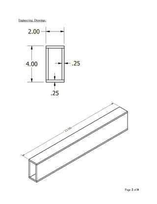
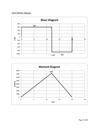
From V-M Diagrams: 𝑉𝑚𝑎𝑥 = 900𝑙𝑏, 𝑀 𝑚𝑎𝑥 = 7200𝑙𝑏 ∙ 𝑖𝑛
Normal Stress: 𝜎 𝑚𝑎𝑥 =
𝑀 𝑚𝑎𝑥 𝑐
𝐼
=
(7200𝑙𝑏∙𝑖𝑛)(2𝑖𝑛)
5.3073𝑖 𝑛4 = 2713.2 𝑝𝑠𝑖
Shear Stress: 𝜏 𝑚𝑎𝑥 =
𝑉 𝑚𝑎𝑥 𝑄
𝐼𝑡
𝑄 = 𝐴∗
𝑦̅∗
𝐴∗
= (2𝑖𝑛)(2𝑖𝑛) − (1.5𝑖𝑛)(1.75𝑖𝑛) = 1.375 𝑖𝑛2
𝑦̅∗
=
(4𝑖 𝑛2)(2𝑖𝑛)−(2.625𝑖 𝑛2 )(.875𝑖𝑛 )
4𝑖 𝑛2 −2.625𝑖 𝑛2 = 1.2386 𝑖𝑛
𝜏 𝑚𝑎𝑥 =
(900𝑙𝑏)(1.375𝑖 𝑛2 )(1.2386𝑖𝑛)
(5.3073𝑖 𝑛4)(0.5𝑖𝑛 )
= 577.61 𝑝𝑠𝑖
Safety Factors:
Normal: 𝜎𝑎𝑙𝑙𝑜𝑤 = 13,800 𝑝𝑠𝑖
𝑆. 𝐹. =
𝜎 𝑎𝑙𝑙𝑜𝑤
𝜎 𝑚𝑎𝑥
=
13,800𝑝𝑠𝑖
2,713.2𝑝𝑠𝑖
= 5.086
Shear: 𝜏 𝑎𝑙𝑙𝑜𝑤 = 2,090 𝑝𝑠𝑖
𝑆. 𝐹. =
𝜏 𝑎𝑙𝑙𝑜𝑤
𝜏 𝑚𝑎𝑥
=
2,090𝑝𝑠𝑖
577.61𝑝𝑠𝑖
= 3.618](https://image.slidesharecdn.com/f5683bb3-be3c-4902-b9bc-c6bab6f67d41-150302215024-conversion-gate01/85/Final-Design-Report-5-320.jpg)
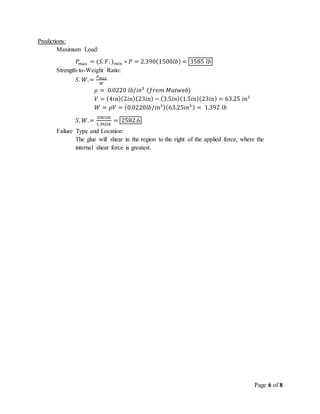
![Page 5 of 8
Glue Stress:
Shear Stress: 𝜏𝑔𝑙𝑢𝑒 =
𝑞
𝑁𝑤
, 𝑞 =
𝑉 𝑚𝑎 𝑥 𝑄
𝐼
𝑄 = 𝐴∗
𝑦̅∗
𝐴∗
= (2𝑖𝑛)(0.25𝑖𝑛) = 0.5 𝑖𝑛2
𝑦̅∗
= 2𝑖𝑛 − (
0.25𝑖𝑛
2
) = 1.875 𝑖𝑛2
𝑞 =
(900𝑙𝑏)(0.5𝑖 𝑛2)(1.875𝑖𝑛)
5.3073𝑖 𝑛4 = 158.99 𝑙𝑏/𝑖𝑛
𝜏𝑔𝑙𝑢𝑒 =
158.99𝑙𝑏/𝑖𝑛
2(.25𝑖𝑛 )
= 317.96 𝑝𝑠𝑖
Safety Factor:
Shear: 𝜏 𝑎𝑙𝑙𝑜𝑤 = 760 𝑝𝑠𝑖
𝑆. 𝐹. =
𝜏 𝑎𝑙𝑙𝑜𝑤
𝜏 𝑚𝑎𝑥
=
760𝑝𝑠𝑖
317.96𝑝𝑠𝑖
= 2.390
Deflection:
𝑀( 𝑥) = 𝐹𝐴 < 𝑥 − 0 >1
− 𝑃 < 𝑥 − 12 >1
+ 𝐹𝐵 < 𝑥 − 20 >1
𝐸𝐼𝑦′( 𝑥) =
𝐹 𝐴
2
𝑥2
−
𝑃
2
< 𝑥 − 12 >2
+ 𝐶1
𝐸𝐼𝑦( 𝑥) =
𝐹 𝐴
6
𝑥3
−
𝑃
6
< 𝑥 − 12 >3
+ 𝐶1 𝑥 + 𝐶2
𝐸 = 1.580 ∗ 106
𝑝𝑠𝑖
Boundary Conditions: 𝑦(0) = 0, 𝑦(20) = 0
Solve for Constants 𝐶1 and 𝐶2
𝑦(0) = 0
0 =
600
6
(0)3
−
1500
6
(0)3
+ 𝐶1(0)+ 𝐶2
𝐶2 = 0
𝑦(20) = 0
0 =
600
6
(20)3
−
1500
6
(20 − 12)3
+ 𝐶1(20)
𝐶1 = −33600 𝑙𝑏 ∙ 𝑖𝑛2
Solve for location where slope equals zero:
0 ≤ 𝑥 ≤ 12
0 =
600
2
𝑥2
−
1500
2
(0)2
− 33600
𝑥 = 10.58 𝑖𝑛
12 < 𝑥 ≤ 20
0 =
600
2
𝑥2
−
1500
2
( 𝑥 − 12)2
− 33600
𝑥 = 10.76 𝑖𝑛, 29.24 𝑖𝑛 (𝑛𝑜𝑡 𝑖𝑛 𝑑𝑜𝑚𝑎𝑖𝑛)
Solve for max deflection:
𝑦 𝑚𝑎𝑥 =
1
𝐸𝐼
[
𝐹 𝐴
6
𝑥3
−
𝑃
6
< 𝑥 − 12 >3
− 33600]
𝑦 𝑚𝑎𝑥 = 𝑦(10.58𝑖𝑛) =
1
8.386 ∗106 𝑙𝑏∙𝑖𝑛2 [
600𝑙𝑏
6
(10.58𝑖𝑛)3
− 33600𝑙𝑏 ∙ 𝑖𝑛2
(10.58𝑖𝑛)]
𝑦 𝑚𝑎𝑥 = −.02827 𝑖𝑛](https://image.slidesharecdn.com/f5683bb3-be3c-4902-b9bc-c6bab6f67d41-150302215024-conversion-gate01/85/Final-Design-Report-6-320.jpg)
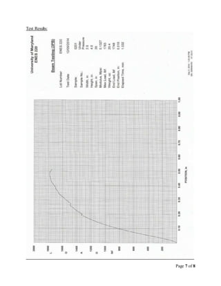
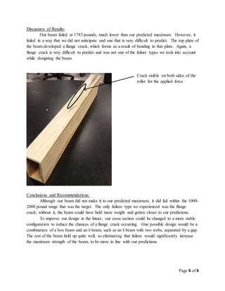

The team designed and tested a wooden beam to hold between 1000-2000 pounds. They calculated stresses and deflections, predicting the beam would fail by glue shear above 3500 pounds. During testing, the beam failed at 1783 pounds due to an unexpected flange crack in the top plate. While the failure load was in the target range, it was lower than predicted. To improve the design, the team recommends a cross-section shape less prone to flange cracks, like an I-beam with double webs.


