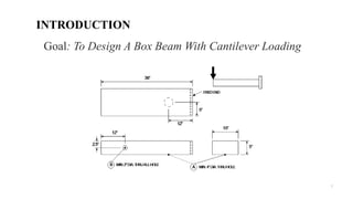
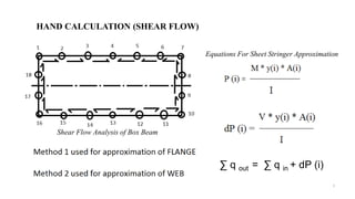
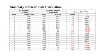
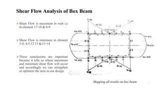
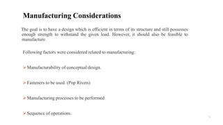
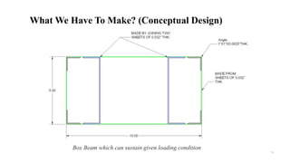
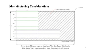
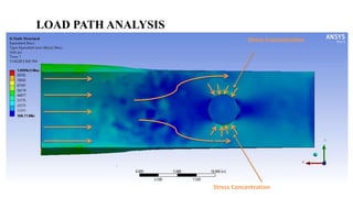
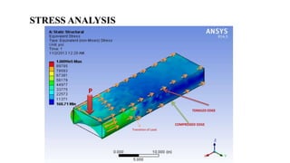
To Design and
Optimize a Box Beam
for Cantilever Loading Case
by Aditya Joshi, Aniket Pande, Mamah Celestine, Praveen Jose, Ranpreet B and Saumitra Gokhale
MECH 5603 Lightweight Structures
Prof.: Dr. Chad English
Date: 7th November 2013
INTRODUCTION
2
Goal: To Design A Box Beam With Cantilever Loading
To obtain various possible designs for the box beam
To shortlist all acceptable designs
To optimize the internal structure of final box beam with a view to maximize
load to weight ratio
To produce detailed manufacturing plan
To use load path/hand calculation to justify the choice of our design
3
PROJECT OBJECTIVES
4
Over the years, numerous researchers have
concluded that
A suspension bridge with tensioned cables is
much efficient (and lighter) than a truss bridge
with welded bars
Minimizing the weight of aircraft or its structures
provides better overall efficiency
A efficiently and intelligently designed structure
makes full use of available resources while
avoiding overdesigning and minimizing load to
weight ratio.
OVERALL MOTIVATIONS
Meeting
Date
% Work
Accomplished
Pre Meeting Tasks Meeting Agenda
15 Sep 3 First Meeting
overall structure of our report /Project
Plan
21 Sep 8
Introduction and theory (Literature Review on Lightweight Structures & Wing
Box)
Finalized Problem Statement
&Objectives
30 Sep 13 Research on rest of the literature review
Brainstorming/Everyone was told to
sketch their own design
6 Oct 15 Write the allotted sections Literature Review and Sketch your own designs 2nd Brainstorming
7 &8 Oct
25 Manufacturing Considerations/hand sketches for the designs
Brainstorming / Design Discussions
13 & 17 Oct
30
Finish Writing the Introduction & Theory of Report
Finalized the Introduction & Theory
Sections of Report with References
22 Oct 35
thoroughly studied method 1 and method 2 for shear flow analysis./reading
on sheet -stringer approximations
Discussion about hand calculations
28 Oct 45
Make 3-d Models in groups of 2
calculations were done for different
designs by referring professor's notes
Project Plan: Group Meetings
Meeting Date
% Work
Accomplished
Pre Meeting Tasks Meeting Agenda
31 Oct 55 Hand calculations on chosen designs in groups of 2
finalized 3-d Models/analysis in Ansys for
stress-deformation visualization
2 Nov 70 make slides for the presentation/do analysis on Ansys Finalized hand calculations
4 Nov 75 Finish the slides for the presentation Presentation finalization
5 Nov/6 Nov 82 rehearse the presentation rehearse the presentation
9 Nov 89
analyze calculations for the 2 designs in groups of 2 Discuss the manufacturing plan /finalize
the final design using the decision matrix
16/23 Nov 96
write method discussion and conclusion of the report
write manufacturing plan and discuss the
pros and cons of the chosen designs
/compilation ,editing and review of the
report/finalize the written report
25 Nov 100
check references and review individually allotted sections finalize the written report/take printouts
0
10
20
30
40
50
60
70
80
90
100%WORKACCOMPLISHED
PROJECT PROGRESS
Project Plan: Progress
8
Moment Diagram
Moment diagram throughout length of the beam.
9
HAND CALCULATION (SHEAR FLOW)
∑ q out = ∑ q in + dP (i)
Shear Flow Analysis of Box Beam
Equations For Sheet Stringer Approximation
10
Summary of Shear Flow Calculation
M = 36000 lbf.in I (FLANGE) = 3.99 IN^4
∑ q out = ∑ q in + dP (i)
V= 1000 lbf I (WEB) = 8 IN^4
NODE AREA (sq inch) P (lb) dP (lb.in) Element q
1 0.0457 1013 28.75 1-2 -71.88
2 0.0457 1013 28.75 2-3 -43.125
3 0.0457 1013 28.75 3-4 -14.375
4 0.0457 1013 28.75 5-4 -14.375
5 0.0457 1013 28.75 6-5 -43.125
6 0.0457 1013 28.75 7-6 -71.88
7 0.0457 1013 28.75 8-7 -100.625
8 0.08 1800 50 9-8 -150.625
9 0.08 -1800 -50 10-9 -100.625
10 0.0457 -1013 28.75 11-10 -71.88
11 0.0457 -1013 28.75 12-11 -43.125
12 0.0457 -1013 28.75 13-12 -14.375
13 0.0457 -1013 28.75 13-14 -14.375
14 0.0457 -1013 28.75 14-15 -43.125
15 0.0457 -1013 28.75 15-16 -71.88
16 0.0457 -1013 28.75 16-17 -100.625
17 0.08 -1800 -50 17-18 -150.625
18 0.08 1800 50 18-1 -100.625
11
Shear Flow is maximum in web i.e
in element 17-18 & 8-9
Shear Flow is minimum in element
3-4, 4-5,12 13 &13=14
These conclusions are important
because it tells us where maximum
and minimum shear flow will occur
and accordingly we can strengthen
or optimize the area in our design.
Shear Flow Analysis of Box Beam
Mapping all results on box beam
12
Following factors were considered related to manufacturing:
Manufacturability of conceptual design.
Fasteners to be used. (Pop Rivets)
Manufacturing processes to be performed
Sequence of operations.
Manufacturing Considerations
The goal is to have a design which is efficient in terms of its structure and still possesses
enough strength to withstand the given load. However, it should also be feasible to
manufacture.
13
What Do We Have?
8ft X 4ft X 0.032” Sheet of 3003-H14 Aluminium
Angle of 1” X 1” X 0.0625”
50ft Long of Aluminium - 6061
All Dimensions are in inches
Box Beam which can sustain given loading condition
14
What We Have To Make? (Conceptual Design)
15
All Dimensions are in inches
Can be used for Ribs if needed
Green dotted lines represent sheet used for Box Beam fabrication
Blue dotted lines represent sheet used for stringers fabrication.
Manufacturing Considerations
LOAD PATH ANALYSIS
Stress Concentration
COMPRESSED EDGE
TENSILED EDGE
Transition of Load
P
STRESS ANALYSIS
18
Reinforcing Cut-Outs (for thick sheets)
19
Reinforcing Cut-Outs (for thin sheets)
Pressing Rib Cut-Outs
20
CONCLUSION
The final design will chosen only after considering all the factors presented here which
means we will make sure that our final design is efficient in terms of load path and
overall weight of the design and that it is feasible to manufacture it.
Questions ??

Final presentation (1)

  • 1.
    To Design and Optimizea Box Beam for Cantilever Loading Case by Aditya Joshi, Aniket Pande, Mamah Celestine, Praveen Jose, Ranpreet B and Saumitra Gokhale MECH 5603 Lightweight Structures Prof.: Dr. Chad English Date: 7th November 2013
  • 2.
    INTRODUCTION 2 Goal: To DesignA Box Beam With Cantilever Loading
  • 3.
    To obtain variouspossible designs for the box beam To shortlist all acceptable designs To optimize the internal structure of final box beam with a view to maximize load to weight ratio To produce detailed manufacturing plan To use load path/hand calculation to justify the choice of our design 3 PROJECT OBJECTIVES
  • 4.
    4 Over the years,numerous researchers have concluded that A suspension bridge with tensioned cables is much efficient (and lighter) than a truss bridge with welded bars Minimizing the weight of aircraft or its structures provides better overall efficiency A efficiently and intelligently designed structure makes full use of available resources while avoiding overdesigning and minimizing load to weight ratio. OVERALL MOTIVATIONS
  • 5.
    Meeting Date % Work Accomplished Pre MeetingTasks Meeting Agenda 15 Sep 3 First Meeting overall structure of our report /Project Plan 21 Sep 8 Introduction and theory (Literature Review on Lightweight Structures & Wing Box) Finalized Problem Statement &Objectives 30 Sep 13 Research on rest of the literature review Brainstorming/Everyone was told to sketch their own design 6 Oct 15 Write the allotted sections Literature Review and Sketch your own designs 2nd Brainstorming 7 &8 Oct 25 Manufacturing Considerations/hand sketches for the designs Brainstorming / Design Discussions 13 & 17 Oct 30 Finish Writing the Introduction & Theory of Report Finalized the Introduction & Theory Sections of Report with References 22 Oct 35 thoroughly studied method 1 and method 2 for shear flow analysis./reading on sheet -stringer approximations Discussion about hand calculations 28 Oct 45 Make 3-d Models in groups of 2 calculations were done for different designs by referring professor's notes Project Plan: Group Meetings
  • 6.
    Meeting Date % Work Accomplished PreMeeting Tasks Meeting Agenda 31 Oct 55 Hand calculations on chosen designs in groups of 2 finalized 3-d Models/analysis in Ansys for stress-deformation visualization 2 Nov 70 make slides for the presentation/do analysis on Ansys Finalized hand calculations 4 Nov 75 Finish the slides for the presentation Presentation finalization 5 Nov/6 Nov 82 rehearse the presentation rehearse the presentation 9 Nov 89 analyze calculations for the 2 designs in groups of 2 Discuss the manufacturing plan /finalize the final design using the decision matrix 16/23 Nov 96 write method discussion and conclusion of the report write manufacturing plan and discuss the pros and cons of the chosen designs /compilation ,editing and review of the report/finalize the written report 25 Nov 100 check references and review individually allotted sections finalize the written report/take printouts
  • 7.
  • 8.
    8 Moment Diagram Moment diagramthroughout length of the beam.
  • 9.
    9 HAND CALCULATION (SHEARFLOW) ∑ q out = ∑ q in + dP (i) Shear Flow Analysis of Box Beam Equations For Sheet Stringer Approximation
  • 10.
    10 Summary of ShearFlow Calculation M = 36000 lbf.in I (FLANGE) = 3.99 IN^4 ∑ q out = ∑ q in + dP (i) V= 1000 lbf I (WEB) = 8 IN^4 NODE AREA (sq inch) P (lb) dP (lb.in) Element q 1 0.0457 1013 28.75 1-2 -71.88 2 0.0457 1013 28.75 2-3 -43.125 3 0.0457 1013 28.75 3-4 -14.375 4 0.0457 1013 28.75 5-4 -14.375 5 0.0457 1013 28.75 6-5 -43.125 6 0.0457 1013 28.75 7-6 -71.88 7 0.0457 1013 28.75 8-7 -100.625 8 0.08 1800 50 9-8 -150.625 9 0.08 -1800 -50 10-9 -100.625 10 0.0457 -1013 28.75 11-10 -71.88 11 0.0457 -1013 28.75 12-11 -43.125 12 0.0457 -1013 28.75 13-12 -14.375 13 0.0457 -1013 28.75 13-14 -14.375 14 0.0457 -1013 28.75 14-15 -43.125 15 0.0457 -1013 28.75 15-16 -71.88 16 0.0457 -1013 28.75 16-17 -100.625 17 0.08 -1800 -50 17-18 -150.625 18 0.08 1800 50 18-1 -100.625
  • 11.
    11 Shear Flow ismaximum in web i.e in element 17-18 & 8-9 Shear Flow is minimum in element 3-4, 4-5,12 13 &13=14 These conclusions are important because it tells us where maximum and minimum shear flow will occur and accordingly we can strengthen or optimize the area in our design. Shear Flow Analysis of Box Beam Mapping all results on box beam
  • 12.
    12 Following factors wereconsidered related to manufacturing: Manufacturability of conceptual design. Fasteners to be used. (Pop Rivets) Manufacturing processes to be performed Sequence of operations. Manufacturing Considerations The goal is to have a design which is efficient in terms of its structure and still possesses enough strength to withstand the given load. However, it should also be feasible to manufacture.
  • 13.
    13 What Do WeHave? 8ft X 4ft X 0.032” Sheet of 3003-H14 Aluminium Angle of 1” X 1” X 0.0625” 50ft Long of Aluminium - 6061 All Dimensions are in inches
  • 14.
    Box Beam whichcan sustain given loading condition 14 What We Have To Make? (Conceptual Design)
  • 15.
    15 All Dimensions arein inches Can be used for Ribs if needed Green dotted lines represent sheet used for Box Beam fabrication Blue dotted lines represent sheet used for stringers fabrication. Manufacturing Considerations
  • 16.
    LOAD PATH ANALYSIS StressConcentration Stress Concentration
  • 17.
  • 18.
  • 19.
    19 Reinforcing Cut-Outs (forthin sheets) Pressing Rib Cut-Outs
  • 20.
    20 CONCLUSION The final designwill chosen only after considering all the factors presented here which means we will make sure that our final design is efficient in terms of load path and overall weight of the design and that it is feasible to manufacture it. Questions ??