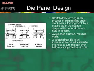
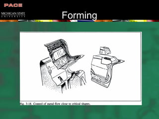
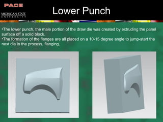
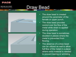
Front Quarter Panel
Final Design
Derek Baker
Eric Ford
Tinikia Nobles
Before and After
Before and After
Adjustments
Before After
Before and After
Front View
Top View
Side View
Bead DevelopmentDie Design Procedure
• Laying out the design for the die
• Detailed drawings of each die part, i.e., punches, punch holders, die
steels
• Design is given to a NC (Neuro-Computing) programmer to
determine the path of the tool
• NC programmer develops the script program
• Input program into the machine controller
• Machine is now ready to create the die
Die Panel Design
• Stretch-draw forming is the
process of cold forming sheet
stock over a forming block by a
mating die of the desired
shape while the workpiece is
held in tension.
• Avoid deep drawing- reduces
costs.
• A stretch draw die in an
inverted draw die will eliminate
the need to turn the part over
before placing into the trim die.
Forming
Trim and flange lines
Trim Edge
Redesign 1
• First redesign involved panel
mating with front door
• Three major problems with the
original design
– Panel should not go all the
way down to the bottom of the
car
– Corner would cause
formability issues
– Flanging would more than
likely cause regional tearing
Before
After
Redesign 2
• Second redesign involved
panel flanging at the base
• The original panel design had
no way of mating the panel to
the frame other than under the
hood
• Issues still remain here where
beading will more than likely
need to be added to the new
flange for rigidity
Before
After
Redesign 3
• Final redesign involved
flanging between panel and
the front door
• The new flange was increased
from just under an inch to over
six inches in length
• The flange is now one of the
more significant attachment
points on the panel
Before
After
Die Tip
• The die tip is the next step
in the die design process.
• Here the high point usually
close to the midpoint of the
panel is determined
• Then the horizontal and
vertical distance is
measured from the high
point to the low point of the
panel to develop the binder
wrap.
Binder Wrap
•Here the binder wrap is developed from the die tip and the overall shape and curvature
of the panel is laid over the sheet.
•The binder wrap will determine the size and shape of the overall blank.
Lower Punch
•The lower punch, the male portion of the draw die was created by extruding the panel
surface off a solid block.
•The formation of the flanges are all placed on a 10-15 degree angle to jump-start the
next die in the process, flanging.
Upper Punch
•The upper punch, the female portion of the die was created by subtracting the panel
shape from a solid block.
•The upper punch will be contacted to the upper shoe of the overall die and will integrate
guide pins for positioning and alignment of the mating of the two dies.
Draw Bead
• The draw bead is created
around the parameter of the
female or upper punch.
• The draw bead provides
control over the flow of the
metal while strain is applied
during operation.
• The draw bead is sometimes
doubled in places where the
metal is prevented from
flowing.
• The absence of a draw bead
can be utilized as well to allow
full flow of the metal in a place
where extra material is needed
to prevent tearing or wrinkling

Final Design Presentation

  • 1.
    Front Quarter Panel FinalDesign Derek Baker Eric Ford Tinikia Nobles
  • 2.
  • 3.
  • 4.
  • 5.
  • 6.
  • 7.
  • 8.
    Bead DevelopmentDie DesignProcedure • Laying out the design for the die • Detailed drawings of each die part, i.e., punches, punch holders, die steels • Design is given to a NC (Neuro-Computing) programmer to determine the path of the tool • NC programmer develops the script program • Input program into the machine controller • Machine is now ready to create the die
  • 9.
    Die Panel Design •Stretch-draw forming is the process of cold forming sheet stock over a forming block by a mating die of the desired shape while the workpiece is held in tension. • Avoid deep drawing- reduces costs. • A stretch draw die in an inverted draw die will eliminate the need to turn the part over before placing into the trim die.
  • 10.
  • 11.
  • 12.
  • 13.
    Redesign 1 • Firstredesign involved panel mating with front door • Three major problems with the original design – Panel should not go all the way down to the bottom of the car – Corner would cause formability issues – Flanging would more than likely cause regional tearing Before After
  • 14.
    Redesign 2 • Secondredesign involved panel flanging at the base • The original panel design had no way of mating the panel to the frame other than under the hood • Issues still remain here where beading will more than likely need to be added to the new flange for rigidity Before After
  • 15.
    Redesign 3 • Finalredesign involved flanging between panel and the front door • The new flange was increased from just under an inch to over six inches in length • The flange is now one of the more significant attachment points on the panel Before After
  • 16.
    Die Tip • Thedie tip is the next step in the die design process. • Here the high point usually close to the midpoint of the panel is determined • Then the horizontal and vertical distance is measured from the high point to the low point of the panel to develop the binder wrap.
  • 17.
    Binder Wrap •Here thebinder wrap is developed from the die tip and the overall shape and curvature of the panel is laid over the sheet. •The binder wrap will determine the size and shape of the overall blank.
  • 18.
    Lower Punch •The lowerpunch, the male portion of the draw die was created by extruding the panel surface off a solid block. •The formation of the flanges are all placed on a 10-15 degree angle to jump-start the next die in the process, flanging.
  • 19.
    Upper Punch •The upperpunch, the female portion of the die was created by subtracting the panel shape from a solid block. •The upper punch will be contacted to the upper shoe of the overall die and will integrate guide pins for positioning and alignment of the mating of the two dies.
  • 20.
    Draw Bead • Thedraw bead is created around the parameter of the female or upper punch. • The draw bead provides control over the flow of the metal while strain is applied during operation. • The draw bead is sometimes doubled in places where the metal is prevented from flowing. • The absence of a draw bead can be utilized as well to allow full flow of the metal in a place where extra material is needed to prevent tearing or wrinkling