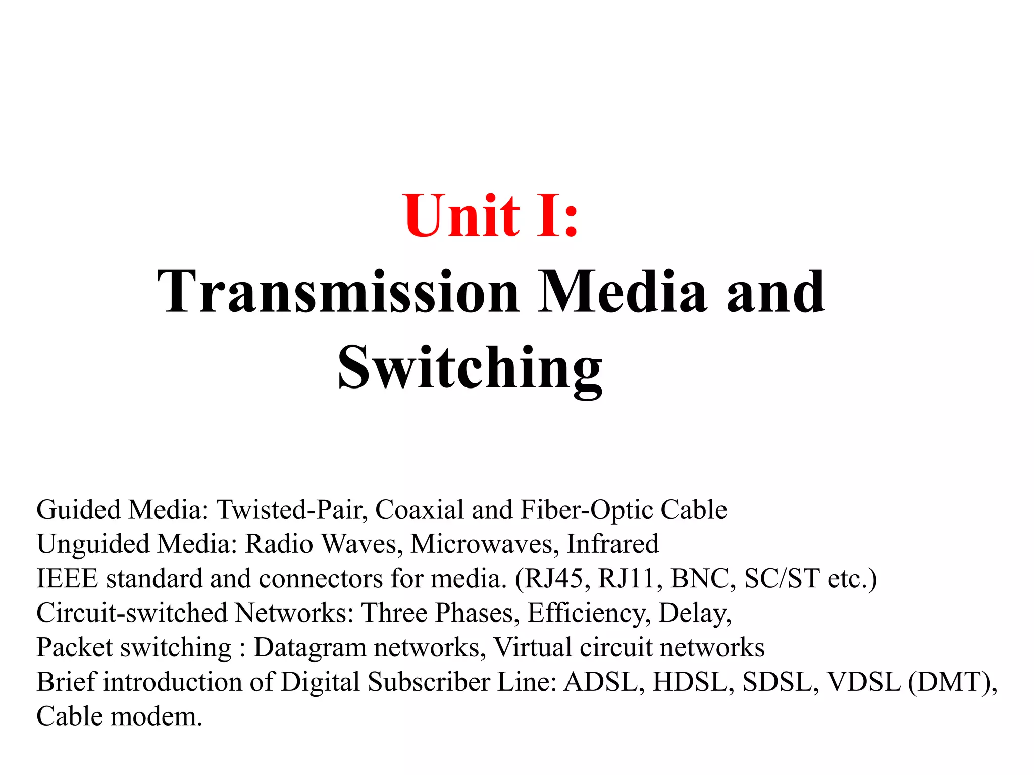
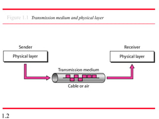
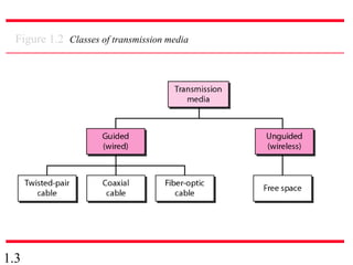
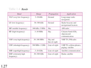
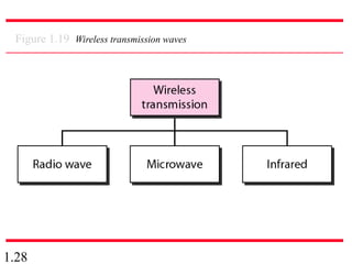
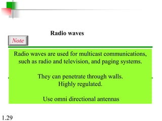
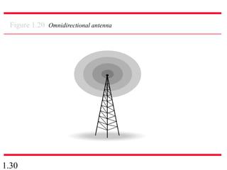
Unit I:
Transmission Media and
Switching
Guided Media: Twisted-Pair, Coaxial and Fiber-Optic Cable
Unguided Media: Radio Waves, Microwaves, Infrared
IEEE standard and connectors for media. (RJ45, RJ11, BNC, SC/ST etc.)
Circuit-switched Networks: Three Phases, Efficiency, Delay,
Packet switching : Datagram networks, Virtual circuit networks
Brief introduction of Digital Subscriber Line: ADSL, HDSL, SDSL, VDSL (DMT),
Cable modem.
1.2
Figure 1.1 Transmission medium and physical layer
1.3
Figure 1.2 Classes of transmission media
1.4
1-1 GUIDED MEDIA
Guided media, which are those that provide a conduit
from one device to another, include twisted-pair cable,
coaxial cable, and fiber-optic cable.
Twisted-Pair Cable
Coaxial Cable
Fiber-Optic Cable
Topics discussed in this section:
1.5
Figure 1.3 Twisted-pair cable
1.6
Figure 1.4 UTP and STP cables
Unshielded Twisted-Pair Cable
Figure 1-8
WCB/McGraw-Hill  The McGraw-Hill Companies, Inc., 1998
Shielded Twisted-Pair Cable
Figure 1-10
WCB/McGraw-Hill  The McGraw-Hill Companies, Inc., 1998
1.9
Table 1.1 Categories of unshielded twisted-pair cables
1.10
Figure 1.5 UTP connector
1.11
Figure 1.6 UTP performance
Gauge is a measure of the thickness of the wire
Twisted Pair
Applications:
1. Telephone lines
2. LAN
1.13
Figure 1.1 Coaxial cable
Coaxial Cable
1.14
Table 1.2 Categories of coaxial cables
1.15
Figure 1.8 BNC connectors
BNC: Bayonet Neil-Concelman
BNC connectors are used to connect end of the cable to a device such as TV Set.
1.16
Figure 1.9 Coaxial cable performance
Has higher attenuation than coaxial cable.
1.17
Figure 1.10 Fiber optics: Bending of light ray
1.18
Figure 1.11 Optical fiber
1.19
Figure 1.13 Modes Index refers to refraction and is related to density
1.20
Table 1.3 Fiber types
1.21
Figure 1.14 Fiber construction
1.22
Figure 1.15 Fiber-optic cable connectors
SC: subscriber connector
standard-duplex fiber-optic connector
ST: straight tip
high-performance fiber-optic connector
Mechanical Transfer Registered Jack. popular for small form factor devices due to its small size
1.23
Figure 1.16 Optical fiber performance
Attenuation is flatter than in the case of twisted and
coaxial cable.
Need fewer repeaters.
1.24
1-2 UNGUIDED MEDIA: WIRELESS
Unguided media transport electromagnetic waves
without using a physical conductor.
This type of communication is often referred to as
wireless communication.
Radio Waves
Microwaves
Infrared
Topics discussed in this section:
1.25
Figure 1.11 Electromagnetic spectrum for wireless communication
1.26
Figure 1.18 Propagation methods
1.27
Table 1.4 Bands
1.28
Figure 1.19 Wireless transmission waves
1.29
Radio waves are used for multicast communications,
such as radio and television, and paging systems.
They can penetrate through walls.
Highly regulated.
Use omni directional antennas
Note
Radio waves
1.30
Figure 1.20 Omnidirectional antenna
1.31
Microwaves are used for unicast communication such
as cellular telephones, satellite networks,
and wireless LANs.
Higher frequency ranges cannot penetrate walls.
Use directional antennas - point to point line of sight
communications.
Note
Microwaves
1.32
Figure 1.21 Unidirectional antennas
1.33
Infrared signals can be used for short-range
communication in a closed area using line-of-sight
propagation.
Note
Infrared
1.34
Wireless Channels
• Are subject to a lot more errors than guided media
channels.
• Interference is one cause for errors, can be
circumvented with high SNR.
• The higher the SNR the less capacity is available
for transmission due to the broadcast nature of the
channel.
• Channel also subject to fading and no coverage
holes.
8.35
Switching at the data link layer in a switched WAN is
normally
implemented by using
virtual-circuit techniques.
Note
8.36
Switching
Copyright © The McGraw-Hill Companies, Inc. Permission required for reproduction or display.
8.37
Figure 8.1 Switched network
8.38
Figure 8.2 Taxonomy of switched networks
8.39
8-1 CIRCUIT-SWITCHED NETWORKS
• A circuit-switched network consists of a set of
switches connected by physical links.
• A connection between two stations is a dedicated
path made of one or more links.
• However, each connection uses only one dedicated
channel on each link.
• Each link is normally divided into n channels by
using FDM or TDM.
Three Phases
Efficiency
Delay
Circuit-Switched Technology in Telephone Networks
Topics discussed in this section:
8.40
A circuit-switched network is made of a set of switches
connected by physical links, in which each link is
divided into n channels.
Note
8.41
Figure 8.3 A trivial circuit-switched network
8.42
In circuit switching, the resources need to be reserved
during the setup phase;
the resources remain dedicated for the entire duration
of data transfer until the teardown phase.
Note
8.43
As a trivial example, let us use a circuit-switched network
to connect eight telephones in a small area.
Communication is through 4-kHz voice channels.
We assume that each link uses FDM to connect a
maximum of two voice channels. The bandwidth of each
link is then 8 kHz.
Figure 8.4 shows the situation. Telephone 1 is connected to
telephone 1; 2 to 5; 3 to 8; and 4 to 6. Of course the
situation may change when new connections are made. The
switch controls the connections.
Example 8.1
8.44
Figure 8.4 Circuit-switched network used in Example 8.1
8.45
As another example, consider a circuit-switched network
that connects computers in two remote offices of a private
company. The offices are connected using a T-1 line leased
from a communication service provider. There are two 4 ×
8 (4 inputs and 8 outputs) switches in this network. For
each switch, four output ports are folded into the input
ports to allow communication between computers in the
same office. Four other output ports allow communication
between the two offices. Figure 8.5 shows the situation.
Example 8.2
8.46
Figure 8.5 Circuit-switched network used in Example 8.2
8.47
Figure 8.6 Delay in a circuit-switched network
8.48
Switching at the physical layer in the traditional
telephone network uses
the circuit-switching approach.
Note
8.49
8-2 DATAGRAM NETWORKS
• In data communications, we need to send messages
from one end system to another.
• If the message is going to pass through a packet-
switched network, it needs to be divided into packets
of fixed or variable size.
• The size of the packet is determined by the network
and the governing protocol.
Routing Table
Efficiency
Delay
Datagram Networks in the Internet
Topics discussed in this section:
8.50
In a packet-switched network, there
is no resource reservation;
resources are allocated on demand.
Note
8.51
Figure 8.1 A datagram network with four Nodes
8.52
Figure 8.8 Routing table in a datagram network
8.53
A switch in a datagram network uses a routing table
that is based on the destination address.
Note
8.54
The destination address in the header of a packet in a
datagram network
remains the same during the entire journey of the
packet.
Note
8.55
Figure 8.9 Delay in a datagram network
8.56
Switching in the Internet is done by using the datagram
approach
to packet switching at
the network layer.
Note
8.57
8-3 VIRTUAL-CIRCUIT NETWORKS
• A virtual-circuit network is a cross between a circuit-
switched network and a datagram network.
• It has some characteristics of both.
Addressing
Three Phases
Efficiency
Delay
Circuit-Switched Technology in WANs
Topics discussed in this section:
8.58
Figure 8.10 Virtual-circuit network
8.59
Figure 8.11 Virtual-circuit identifier
8.60
Figure 8.12 Switch and tables in a virtual-circuit network
8.61
Figure 8.13 Source-to-destination data transfer in a virtual-circuit network
8.62
Figure 8.14 Setup request in a virtual-circuit network
8.63
Figure 8.15 Setup acknowledgment in a virtual-circuit network
8.64
In virtual-circuit switching, all packets belonging to the
same source and
destination travel the same path;
but the packets may arrive at the destination with
different delays
if resource allocation is on demand.
Note
8.65
Figure 8.16 Delay in a virtual-circuit network
Types of communication
systems:
Landline
communication
system
Telephone DSL
Cellular and mobile
communication
system
Mobile phone
network
What is a Landline?
• A landline is a physical connection between two
devices.
• Example on a Landline:
• Landline Phone (metal wire or fiber cable)
History Of Telephone
Alexander Graham
inventing the first
practical telephone.
Thomas Edison,
invented the carbon
microphone which
produced a strong
telephone signal
Bell on the telephone in New
York (calling Chicago) in 1892
Evolution in Telephone
9.71
DIAL-UP MODEMS
• Traditional telephone lines can carry frequencies
between 300 and 3300 Hz, giving them a bandwidth
of 3000 Hz.
• All this range is used for transmitting voice, where a
great deal of interference and distortion can be
accepted without loss of intelligibility.
Modem Standards
Topics discussed in this section:
9.72
Figure 9.6 Telephone line bandwidth
9.73
Modem
stands for modulator/demodulator.
Note
9.74
Figure 9.1 Modulation/demodulation
9.75
Figure 9.9 Uploading and downloading in 56K modems
9.76
9-3 DIGITAL SUBSCRIBER LINE
• After traditional modems reached their peak data rate, telephone
companies developed another technology, DSL, to provide higher-
speed access to the Internet.
• Digital subscriber line (DSL) technology is one of the most
promising for supporting high-speed digital communication over
the existing local loops.
• It is a technology that brings huge data and information to homes
and small businesses over ordinary telephone lines.
• Different variations of DSL, such as ADSL, HDSL, IDSL, VDSL
and RADSL.
DSL
• Originally designed to carry “Data”.
• 25kHz to 1.1MHz.
• In one wire:
– Phone call data + Internet data = ?
BUT IN DIFFERENT FREQUENCIES
The Splitter
The Splitter
• One input and two outs device:
– Phone output get.
– DSL output get.
• Phone output gat is a Low-pass filter:
– It passes DC to 3.4kHz.
9.80
ADSL is an asymmetric communication technology
designed for residential users; it is not suitable for
businesses.
Note
9.81
The existing local loops can handle bandwidths up to
1.1 MHz.
Note
9.82
ADSL is an adaptive technology.
The system uses a data rate
based on the condition of
the local loop line.
Note
9.83
Figure 9.10 Discrete multitone technique
9.84
Figure 9.11 Bandwidth division in ADSL
9.86
Figure 9.12 ADSL modem
9.87
Figure 9.13 DSLAM (Digital Subscriber Line Access Multiplexer)
A symmetric digital subscriber line (SDSL) is a
digital subscriber line that transmits digital data over
the copper wires of the telephone network, where the
bandwidth in the downstream direction, from the
network to the subscriber, is identical to the
bandwidth in the upstream direction, from the
subscriber to the network.
High-bit-rate digital subscriber line (HDSL) is a
telecommunications protocol standardized in 1994. It
was the first digital subscriber line (DSL) technology
to use a higher frequency spectrum over copper,
twisted pair cables.
Very-high-bit-rate digital subscriber line (VDSL)
and very-high-bit-rate digital subscriber line 2
(VDSL2) are digital subscriber line (DSL)
technologies providing data transmission faster than
asymmetric digital subscriber line (ADSL).
9.90
Table 9.2 Summary of DSL technologies
DSL Advantages
• DSL does not tie up the phone line.
• Higher speed.
• DSL doesn't necessarily require new wiring.
• Some companies that offers DSL will usually
provide the modem as part of the installation.
DSL Disadvantages
- The farther you are from the central office, the slower
your connection is. As you move away from the central
office, more distortion enters the line and the signal
deteriorates.
- The connection is faster for receiving data than it is for
sending data over the Internet.
- The service is not available everywhere.
8.96
8-4 STRUCTURE OF A SWITCH
• We use switches in circuit-switched and packet-
switched networks.
• In this section, we discuss the structures of the
switches used in each type of network.
Structure of Circuit Switches
Structure of Packet Switches
Topics discussed in this section:
8.97
Figure 8.11 Crossbar switch with three inputs and four outputs
8.98
Figure 8.18 Multistage switch
8.99
In a three-stage switch, the total
number of crosspoints is
2kN + k(N/n)2
which is much smaller than the number of crosspoints
in a single-stage switch (N2).
Note
8.100
Design a three-stage, 200 × 200 switch (N = 200) with
k = 4 and n = 20.
Solution
In the first stage we have N/n or 10 crossbars, each of size
20 × 4. In the second stage, we have 4 crossbars, each of
size 10 × 10. In the third stage, we have 10 crossbars, each
of size 4 × 20. The total number of crosspoints is 2kN +
k(N/n)2, or 2000 crosspoints. This is 5 percent of the
number of crosspoints in a single-stage switch (200 × 200
= 40,000).
Example 8.3
8.101
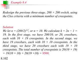
According to the Clos criterion:
n = (N/2)1/2
k > 2n – 1
Crosspoints ≥ 4N [(2N)1/2 – 1]
Note
8.102
Redesign the previous three-stage, 200 × 200 switch, using
the Clos criteria with a minimum number of crosspoints.
Solution
We let n = (200/2)1/2, or n = 10. We calculate k = 2n − 1 =
19. In the first stage, we have 200/10, or 20, crossbars,
each with 10 × 19 crosspoints. In the second stage, we
have 19 crossbars, each with 10 × 10 crosspoints. In the
third stage, we have 20 crossbars each with 19 × 10
crosspoints. The total number of crosspoints is 20(10 × 19)
+ 19(10 × 10) + 20(19 ×10) = 9500.
Example 8.4
8.103
Figure 8.19 Time-slot interchange
8.104
Figure 8.20 Time-space-time switch
8.105
Figure 8.21 Packet switch components
8.106
Figure 8.22 Input port
8.107
Figure 8.23 Output port
8.108
Figure 8.24 A banyan switch
8.109
Figure 8.25 Examples of routing in a banyan switch
8.110
Figure 8.26 Batcher-banyan switch
Electromagnetic Spectrum
Figure 1-1
WCB/McGraw-Hill  The McGraw-Hill Companies, Inc., 1998
4.112
REFERENCEs
1. Fourauzan B., "Data Communications and Networking",
5th edition, McGraw-Hill Publications
2. Stallings William., "Data and Computer Communications",
Sixth Edition, Prentice Hall of India

FCN Unit-I_PPT.pdf

  • 1.
    Unit I: Transmission Mediaand Switching Guided Media: Twisted-Pair, Coaxial and Fiber-Optic Cable Unguided Media: Radio Waves, Microwaves, Infrared IEEE standard and connectors for media. (RJ45, RJ11, BNC, SC/ST etc.) Circuit-switched Networks: Three Phases, Efficiency, Delay, Packet switching : Datagram networks, Virtual circuit networks Brief introduction of Digital Subscriber Line: ADSL, HDSL, SDSL, VDSL (DMT), Cable modem.
  • 2.
    1.2 Figure 1.1 Transmissionmedium and physical layer
  • 3.
    1.3 Figure 1.2 Classesof transmission media
  • 4.
    1.4 1-1 GUIDED MEDIA Guidedmedia, which are those that provide a conduit from one device to another, include twisted-pair cable, coaxial cable, and fiber-optic cable. Twisted-Pair Cable Coaxial Cable Fiber-Optic Cable Topics discussed in this section:
  • 5.
  • 6.
    1.6 Figure 1.4 UTPand STP cables
  • 7.
    Unshielded Twisted-Pair Cable Figure1-8 WCB/McGraw-Hill  The McGraw-Hill Companies, Inc., 1998
  • 8.
    Shielded Twisted-Pair Cable Figure1-10 WCB/McGraw-Hill  The McGraw-Hill Companies, Inc., 1998
  • 9.
    1.9 Table 1.1 Categoriesof unshielded twisted-pair cables
  • 10.
  • 11.
    1.11 Figure 1.6 UTPperformance Gauge is a measure of the thickness of the wire
  • 12.
  • 13.
    1.13 Figure 1.1 Coaxialcable Coaxial Cable
  • 14.
    1.14 Table 1.2 Categoriesof coaxial cables
  • 15.
    1.15 Figure 1.8 BNCconnectors BNC: Bayonet Neil-Concelman BNC connectors are used to connect end of the cable to a device such as TV Set.
  • 16.
    1.16 Figure 1.9 Coaxialcable performance Has higher attenuation than coaxial cable.
  • 17.
    1.17 Figure 1.10 Fiberoptics: Bending of light ray
  • 18.
  • 19.
    1.19 Figure 1.13 ModesIndex refers to refraction and is related to density
  • 20.
  • 21.
  • 22.
    1.22 Figure 1.15 Fiber-opticcable connectors SC: subscriber connector standard-duplex fiber-optic connector ST: straight tip high-performance fiber-optic connector Mechanical Transfer Registered Jack. popular for small form factor devices due to its small size
  • 23.
    1.23 Figure 1.16 Opticalfiber performance Attenuation is flatter than in the case of twisted and coaxial cable. Need fewer repeaters.
  • 24.
    1.24 1-2 UNGUIDED MEDIA:WIRELESS Unguided media transport electromagnetic waves without using a physical conductor. This type of communication is often referred to as wireless communication. Radio Waves Microwaves Infrared Topics discussed in this section:
  • 25.
    1.25 Figure 1.11 Electromagneticspectrum for wireless communication
  • 26.
  • 27.
  • 28.
    1.28 Figure 1.19 Wirelesstransmission waves
  • 29.
    1.29 Radio waves areused for multicast communications, such as radio and television, and paging systems. They can penetrate through walls. Highly regulated. Use omni directional antennas Note Radio waves
  • 30.
  • 31.
    1.31 Microwaves are usedfor unicast communication such as cellular telephones, satellite networks, and wireless LANs. Higher frequency ranges cannot penetrate walls. Use directional antennas - point to point line of sight communications. Note Microwaves
  • 32.
  • 33.
    1.33 Infrared signals canbe used for short-range communication in a closed area using line-of-sight propagation. Note Infrared
  • 34.
    1.34 Wireless Channels • Aresubject to a lot more errors than guided media channels. • Interference is one cause for errors, can be circumvented with high SNR. • The higher the SNR the less capacity is available for transmission due to the broadcast nature of the channel. • Channel also subject to fading and no coverage holes.
  • 35.
    8.35 Switching at thedata link layer in a switched WAN is normally implemented by using virtual-circuit techniques. Note
  • 36.
    8.36 Switching Copyright © TheMcGraw-Hill Companies, Inc. Permission required for reproduction or display.
  • 37.
  • 38.
    8.38 Figure 8.2 Taxonomyof switched networks
  • 39.
    8.39 8-1 CIRCUIT-SWITCHED NETWORKS •A circuit-switched network consists of a set of switches connected by physical links. • A connection between two stations is a dedicated path made of one or more links. • However, each connection uses only one dedicated channel on each link. • Each link is normally divided into n channels by using FDM or TDM. Three Phases Efficiency Delay Circuit-Switched Technology in Telephone Networks Topics discussed in this section:
  • 40.
    8.40 A circuit-switched networkis made of a set of switches connected by physical links, in which each link is divided into n channels. Note
  • 41.
    8.41 Figure 8.3 Atrivial circuit-switched network
  • 42.
    8.42 In circuit switching,the resources need to be reserved during the setup phase; the resources remain dedicated for the entire duration of data transfer until the teardown phase. Note
  • 43.
    8.43 As a trivialexample, let us use a circuit-switched network to connect eight telephones in a small area. Communication is through 4-kHz voice channels. We assume that each link uses FDM to connect a maximum of two voice channels. The bandwidth of each link is then 8 kHz. Figure 8.4 shows the situation. Telephone 1 is connected to telephone 1; 2 to 5; 3 to 8; and 4 to 6. Of course the situation may change when new connections are made. The switch controls the connections. Example 8.1
  • 44.
    8.44 Figure 8.4 Circuit-switchednetwork used in Example 8.1
  • 45.
    8.45 As another example,consider a circuit-switched network that connects computers in two remote offices of a private company. The offices are connected using a T-1 line leased from a communication service provider. There are two 4 × 8 (4 inputs and 8 outputs) switches in this network. For each switch, four output ports are folded into the input ports to allow communication between computers in the same office. Four other output ports allow communication between the two offices. Figure 8.5 shows the situation. Example 8.2
  • 46.
    8.46 Figure 8.5 Circuit-switchednetwork used in Example 8.2
  • 47.
    8.47 Figure 8.6 Delayin a circuit-switched network
  • 48.
    8.48 Switching at thephysical layer in the traditional telephone network uses the circuit-switching approach. Note
  • 49.
    8.49 8-2 DATAGRAM NETWORKS •In data communications, we need to send messages from one end system to another. • If the message is going to pass through a packet- switched network, it needs to be divided into packets of fixed or variable size. • The size of the packet is determined by the network and the governing protocol. Routing Table Efficiency Delay Datagram Networks in the Internet Topics discussed in this section:
  • 50.
    8.50 In a packet-switchednetwork, there is no resource reservation; resources are allocated on demand. Note
  • 51.
    8.51 Figure 8.1 Adatagram network with four Nodes
  • 52.
    8.52 Figure 8.8 Routingtable in a datagram network
  • 53.
    8.53 A switch ina datagram network uses a routing table that is based on the destination address. Note
  • 54.
    8.54 The destination addressin the header of a packet in a datagram network remains the same during the entire journey of the packet. Note
  • 55.
    8.55 Figure 8.9 Delayin a datagram network
  • 56.
    8.56 Switching in theInternet is done by using the datagram approach to packet switching at the network layer. Note
  • 57.
    8.57 8-3 VIRTUAL-CIRCUIT NETWORKS •A virtual-circuit network is a cross between a circuit- switched network and a datagram network. • It has some characteristics of both. Addressing Three Phases Efficiency Delay Circuit-Switched Technology in WANs Topics discussed in this section:
  • 58.
  • 59.
  • 60.
    8.60 Figure 8.12 Switchand tables in a virtual-circuit network
  • 61.
    8.61 Figure 8.13 Source-to-destinationdata transfer in a virtual-circuit network
  • 62.
    8.62 Figure 8.14 Setuprequest in a virtual-circuit network
  • 63.
    8.63 Figure 8.15 Setupacknowledgment in a virtual-circuit network
  • 64.
    8.64 In virtual-circuit switching,all packets belonging to the same source and destination travel the same path; but the packets may arrive at the destination with different delays if resource allocation is on demand. Note
  • 65.
    8.65 Figure 8.16 Delayin a virtual-circuit network
  • 66.
    Types of communication systems: Landline communication system TelephoneDSL Cellular and mobile communication system Mobile phone network
  • 67.
    What is aLandline? • A landline is a physical connection between two devices. • Example on a Landline: • Landline Phone (metal wire or fiber cable)
  • 68.
    History Of Telephone AlexanderGraham inventing the first practical telephone. Thomas Edison, invented the carbon microphone which produced a strong telephone signal
  • 69.
    Bell on thetelephone in New York (calling Chicago) in 1892
  • 70.
  • 71.
    9.71 DIAL-UP MODEMS • Traditionaltelephone lines can carry frequencies between 300 and 3300 Hz, giving them a bandwidth of 3000 Hz. • All this range is used for transmitting voice, where a great deal of interference and distortion can be accepted without loss of intelligibility. Modem Standards Topics discussed in this section:
  • 72.
  • 73.
  • 74.
  • 75.
    9.75 Figure 9.9 Uploadingand downloading in 56K modems
  • 76.
    9.76 9-3 DIGITAL SUBSCRIBERLINE • After traditional modems reached their peak data rate, telephone companies developed another technology, DSL, to provide higher- speed access to the Internet. • Digital subscriber line (DSL) technology is one of the most promising for supporting high-speed digital communication over the existing local loops. • It is a technology that brings huge data and information to homes and small businesses over ordinary telephone lines. • Different variations of DSL, such as ADSL, HDSL, IDSL, VDSL and RADSL.
  • 77.
    DSL • Originally designedto carry “Data”. • 25kHz to 1.1MHz. • In one wire: – Phone call data + Internet data = ? BUT IN DIFFERENT FREQUENCIES
  • 78.
  • 79.
    The Splitter • Oneinput and two outs device: – Phone output get. – DSL output get. • Phone output gat is a Low-pass filter: – It passes DC to 3.4kHz.
  • 80.
    9.80 ADSL is anasymmetric communication technology designed for residential users; it is not suitable for businesses. Note
  • 81.
    9.81 The existing localloops can handle bandwidths up to 1.1 MHz. Note
  • 82.
    9.82 ADSL is anadaptive technology. The system uses a data rate based on the condition of the local loop line. Note
  • 83.
    9.83 Figure 9.10 Discretemultitone technique
  • 84.
  • 86.
  • 87.
    9.87 Figure 9.13 DSLAM(Digital Subscriber Line Access Multiplexer)
  • 88.
    A symmetric digitalsubscriber line (SDSL) is a digital subscriber line that transmits digital data over the copper wires of the telephone network, where the bandwidth in the downstream direction, from the network to the subscriber, is identical to the bandwidth in the upstream direction, from the subscriber to the network.
  • 89.
    High-bit-rate digital subscriberline (HDSL) is a telecommunications protocol standardized in 1994. It was the first digital subscriber line (DSL) technology to use a higher frequency spectrum over copper, twisted pair cables. Very-high-bit-rate digital subscriber line (VDSL) and very-high-bit-rate digital subscriber line 2 (VDSL2) are digital subscriber line (DSL) technologies providing data transmission faster than asymmetric digital subscriber line (ADSL).
  • 90.
    9.90 Table 9.2 Summaryof DSL technologies
  • 91.
    DSL Advantages • DSLdoes not tie up the phone line. • Higher speed. • DSL doesn't necessarily require new wiring. • Some companies that offers DSL will usually provide the modem as part of the installation.
  • 92.
    DSL Disadvantages - Thefarther you are from the central office, the slower your connection is. As you move away from the central office, more distortion enters the line and the signal deteriorates. - The connection is faster for receiving data than it is for sending data over the Internet. - The service is not available everywhere.
  • 96.
    8.96 8-4 STRUCTURE OFA SWITCH • We use switches in circuit-switched and packet- switched networks. • In this section, we discuss the structures of the switches used in each type of network. Structure of Circuit Switches Structure of Packet Switches Topics discussed in this section:
  • 97.
    8.97 Figure 8.11 Crossbarswitch with three inputs and four outputs
  • 98.
  • 99.
    8.99 In a three-stageswitch, the total number of crosspoints is 2kN + k(N/n)2 which is much smaller than the number of crosspoints in a single-stage switch (N2). Note
  • 100.
    8.100 Design a three-stage,200 × 200 switch (N = 200) with k = 4 and n = 20. Solution In the first stage we have N/n or 10 crossbars, each of size 20 × 4. In the second stage, we have 4 crossbars, each of size 10 × 10. In the third stage, we have 10 crossbars, each of size 4 × 20. The total number of crosspoints is 2kN + k(N/n)2, or 2000 crosspoints. This is 5 percent of the number of crosspoints in a single-stage switch (200 × 200 = 40,000). Example 8.3
  • 101.
    8.101 According to theClos criterion: n = (N/2)1/2 k > 2n – 1 Crosspoints ≥ 4N [(2N)1/2 – 1] Note
  • 102.
    8.102 Redesign the previousthree-stage, 200 × 200 switch, using the Clos criteria with a minimum number of crosspoints. Solution We let n = (200/2)1/2, or n = 10. We calculate k = 2n − 1 = 19. In the first stage, we have 200/10, or 20, crossbars, each with 10 × 19 crosspoints. In the second stage, we have 19 crossbars, each with 10 × 10 crosspoints. In the third stage, we have 20 crossbars each with 19 × 10 crosspoints. The total number of crosspoints is 20(10 × 19) + 19(10 × 10) + 20(19 ×10) = 9500. Example 8.4
  • 103.
  • 104.
  • 105.
    8.105 Figure 8.21 Packetswitch components
  • 106.
  • 107.
  • 108.
    8.108 Figure 8.24 Abanyan switch
  • 109.
    8.109 Figure 8.25 Examplesof routing in a banyan switch
  • 110.
  • 111.
    Electromagnetic Spectrum Figure 1-1 WCB/McGraw-Hill The McGraw-Hill Companies, Inc., 1998
  • 112.
    4.112 REFERENCEs 1. Fourauzan B.,"Data Communications and Networking", 5th edition, McGraw-Hill Publications 2. Stallings William., "Data and Computer Communications", Sixth Edition, Prentice Hall of India