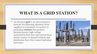
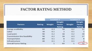
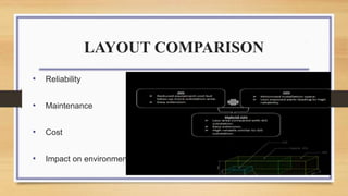
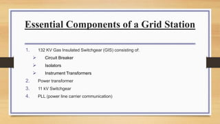
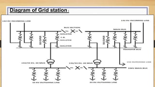
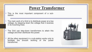
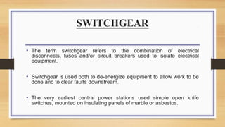
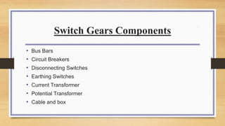
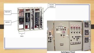
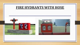
FACILITIES PLANNING
GRID STATION
Presented by
Habib Ali Khan 17517
Hafiz Muhammad Shakir Panjwani 17643
Muhammad Ahmed Ghias 17202
Ammad 15882
INSTRUCTOR:
DR AMIR IQBAL
GRID STATION FACILITY
WHAT IS A GRID STATION?
• An electrical grid is an interconnected
network for delivering electricity from
suppliers to consumers. It consists of
generating stations that produce
electrical power, high-voltage
transmission lines that carry power from
distant sources to demand centers, and
distribution lines that connect individual
customers.
Grid Station Functions
• Voltage Regulation
• Voltage Transformation
• Measure Electrical Power Quantity
• Connect Electrical power generating Plants to the system
• Control Of active and reactive and reactive power
LOCATION SELECTION
• Economic and Technical Feasibility
• Load point & requirement
• Bearable Cost (development, Site distance from existing network, misc.
cost)
• Area Required
• Transmission line feasibility
• Near-by Grid Capacity
• Transport Network
TYPES OF GRID STATION LAYOUTS
• AIR INSULATED SUB-STATION LAYOUT
• GAS INSULATED SUB-STATION LAYOUT
• HYBRID INSULATED SUB-STATION LAYOUT
FACTOR RATING METHOD
LAYOUT COMPARISON
• Reliability
• Maintenance
• Cost
• Impact on environment
Components of Grid Station
Essential Components of a Grid Station
1. 132 KV Gas Insulated Switchgear (GIS) consisting of:
 Circuit Breaker
 Isolators
 Instrument Transformers
2. Power transformer
3. 11 kV Switchgear
4. PLL (power line carrier communication)
Diagram of Grid station :
Power Transformer
• This is the most important component of a sub-
station.
• The main work of a Grid is to distribute power at a low
voltage, by stepping down the voltage that it receives
in its incoming lines.
• The Grid use step-down transformers to attain this
voltage and then distribute this power.
• All the other equipment in a sub-station works only to
facilitate the smooth working of the power
transformer.
SWITCHGEAR
• The term switchgear refers to the combination of electrical
disconnects, fuses and/or circuit breakers used to isolate electrical
equipment.
• Switchgear is used both to de-energize equipment to allow work to be
done and to clear faults downstream.
• The very earliest central power stations used simple open knife
switches, mounted on insulating panels of marble or asbestos.
Switch Gears Components
• Bus Bars
• Circuit Breakers
• Disconnecting Switches
• Earthing Switches
• Current Transformer
• Potential Transformer
• Cable and box
11 KV Switch gears
• Operated at 12 KV
• Work at 630 A
• Load break switch
• Earthing switch
• O/C and E/F Self powered relay
Power line carrier communication
Need of PLCC
• PLCC uses the same high voltage transmission
line connecting two substations for
Telecommunication purpose.
• PLCC is used in all power utilities as a primary
communication service to transmit speech,
• Telemetry and protection tripping commands. This
economic and reliable for inter grid message as
well as low bit RTU signal
• Avoid dependence of busy telephone lines.
• To cope up with ever increasing size of power
grid
Power line carrier communication
• Voice signal modulated on carrier frequency and transmitted on
power line
• No need for lying separate cable for transmission
• Integrates transmission of voice and data through same line
• Allows flow of information through same cording which supplies
electrical power.
SERGI Transformer Protection
• This transformer protection concept can be applied to all oil-
filled transformers. It serves to:
• Depressurize tanks within milliseconds
• Avoid contact between air (Oxygen) and the evacuated
explosive gases (Hydrogen, Acetylene, etc.)
• Separate gases from the oil
• Channel the flammable gases away from the
transformer to a remote area
• Evacuate the explosive gases from the transformer
tank by injecting an inert gas (Nitrogen) into the tank
and associated equipment
• Secure the transformer to let the maintenance staff to
quickly repair safely.
FACILITY LAYOUT
The objective of plant layout planning is a more effective
work flow at the facility, allowing workers and equipment
being more productive
OBJECTIVES OF LAYOUT
1. Sense of unity
2. Safety
3. Flexibility
4. Minimum movement of people material & resources
GRID STATION LAYOUT
• Product-oriented layout: Seeks the best personnel and machine
utilizations in repetitive or continuous production: GRID STATION
DISADVANTAGES
1. High volume is required
2. Work stoppage at any point ties up the whole operation
3. Lack of flexibility in product or production rates
LAYOUT OF GRID STATION
132kV AIS FIELD
11kV Switchgear Room
Capacitor Room
Battery Bank Room
AC/DC Room
Control Room
PLC Room
 Power Transformer Area
 Office
 Toilet
 Pantry
 Store
 Generator Area
 Auxiliary Transformer Area
AIR INSULATED SUB-STATION
GAS INSULATED SUB-STATION
HYBRID INSULATED SUB-STATION
Top View of Ground Floor Plan
Top View of Building First Floor
TRENCH LAYOUT FOR CABLES
GIS AND TRANSFORMER LAYOUT
FIRE STRATEGY
FOR GRID STATION
FACILITY: BEFORE FIRE
FACILITY: AFTER FIRE
FIRE STRATEGY
FOLLOWING ARE THE POSSIBLE CAUSES OF FIRE IN A GRID STATION:
Overheating of equipment/wires
Flash/Spark
Seismic Events
Short Circuit
Law & order
FIRE STRATEGY
Facility designer prepares a fire strategy to counter, minimize
losses & to ensure safety of life and property.
A proper fire strategy is included in our Grid Station design
A proper fire suppression system is installed in our Grid
Station.
FIRE STRATEGY
A proper fire suppression system is installed in our Grid Station
consisting of following components:
1. Fire smoke detectors
2. Fire Alarm system
3. Fire sprinklers
4. Fire hose cabinets with reels
5. Portable fire extinguishers
6. Fire pumps
FIRE STRATEGY
FIRE ESCAPE
• Evacuation in case of fire is a major concern and therefore the layout keeps in its
mind fire exits
• There are normal stairs that can be used as well as emergency exits has been provided
CALCULATION
• MAXIMUM OCCUPANTS IN GRID STATION
Max population=40ft*141ft/100sqft per person=56.4=56 people
• MINIMUM NUMBER OF EXITS=2 from below table
The distance between exits
= diagnol /8=146/8=18ft
one way
FIRE ESCAPE
Fire Exits
FIRE ESCAPE
Fire Exits
FIRE ESCAPE
FIRE PROTECTION
FIRE INDICATOR PANEL
FIRE HYDRANTS WITH HOSE
CO2 Fire Protection System
CO2 FIRE PROTECTION SYSTEM
NFPA
• NATIONAL FIRE PROTECTION ASSOCIATION
• ESTABLISHES CODES & STANDARDS
• MAIN AIM IS TO MINIMIZE BURDEN OF WORLD FIRE
• OVER 65000 MEMBERS WORLDWIDE
CLASSES OF FIRE AS DEFINED BY
NFPA
• Class A fires: Involves Organic material
• Class B fires: Involves flammable liquids
• Class C fires: Involves energized electrical equipment's
• Class D fires: Involves exotic metals
Electrical fires are Class C fires
The End
Any Question!!

Facilities Planning at KE

  • 1.
    FACILITIES PLANNING GRID STATION Presentedby Habib Ali Khan 17517 Hafiz Muhammad Shakir Panjwani 17643 Muhammad Ahmed Ghias 17202 Ammad 15882 INSTRUCTOR: DR AMIR IQBAL
  • 2.
  • 3.
    WHAT IS AGRID STATION? • An electrical grid is an interconnected network for delivering electricity from suppliers to consumers. It consists of generating stations that produce electrical power, high-voltage transmission lines that carry power from distant sources to demand centers, and distribution lines that connect individual customers.
  • 4.
    Grid Station Functions •Voltage Regulation • Voltage Transformation • Measure Electrical Power Quantity • Connect Electrical power generating Plants to the system • Control Of active and reactive and reactive power
  • 5.
    LOCATION SELECTION • Economicand Technical Feasibility • Load point & requirement • Bearable Cost (development, Site distance from existing network, misc. cost) • Area Required • Transmission line feasibility • Near-by Grid Capacity • Transport Network
  • 6.
    TYPES OF GRIDSTATION LAYOUTS • AIR INSULATED SUB-STATION LAYOUT • GAS INSULATED SUB-STATION LAYOUT • HYBRID INSULATED SUB-STATION LAYOUT
  • 7.
  • 8.
    LAYOUT COMPARISON • Reliability •Maintenance • Cost • Impact on environment
  • 9.
  • 10.
    Essential Components ofa Grid Station 1. 132 KV Gas Insulated Switchgear (GIS) consisting of:  Circuit Breaker  Isolators  Instrument Transformers 2. Power transformer 3. 11 kV Switchgear 4. PLL (power line carrier communication)
  • 11.
    Diagram of Gridstation :
  • 12.
    Power Transformer • Thisis the most important component of a sub- station. • The main work of a Grid is to distribute power at a low voltage, by stepping down the voltage that it receives in its incoming lines. • The Grid use step-down transformers to attain this voltage and then distribute this power. • All the other equipment in a sub-station works only to facilitate the smooth working of the power transformer.
  • 13.
    SWITCHGEAR • The termswitchgear refers to the combination of electrical disconnects, fuses and/or circuit breakers used to isolate electrical equipment. • Switchgear is used both to de-energize equipment to allow work to be done and to clear faults downstream. • The very earliest central power stations used simple open knife switches, mounted on insulating panels of marble or asbestos.
  • 14.
    Switch Gears Components •Bus Bars • Circuit Breakers • Disconnecting Switches • Earthing Switches • Current Transformer • Potential Transformer • Cable and box
  • 16.
    11 KV Switchgears • Operated at 12 KV • Work at 630 A • Load break switch • Earthing switch • O/C and E/F Self powered relay
  • 17.
    Power line carriercommunication Need of PLCC • PLCC uses the same high voltage transmission line connecting two substations for Telecommunication purpose. • PLCC is used in all power utilities as a primary communication service to transmit speech, • Telemetry and protection tripping commands. This economic and reliable for inter grid message as well as low bit RTU signal • Avoid dependence of busy telephone lines. • To cope up with ever increasing size of power grid
  • 18.
    Power line carriercommunication • Voice signal modulated on carrier frequency and transmitted on power line • No need for lying separate cable for transmission • Integrates transmission of voice and data through same line • Allows flow of information through same cording which supplies electrical power.
  • 19.
  • 20.
    SERGI Transformer Protection •This transformer protection concept can be applied to all oil- filled transformers. It serves to: • Depressurize tanks within milliseconds • Avoid contact between air (Oxygen) and the evacuated explosive gases (Hydrogen, Acetylene, etc.) • Separate gases from the oil • Channel the flammable gases away from the transformer to a remote area • Evacuate the explosive gases from the transformer tank by injecting an inert gas (Nitrogen) into the tank and associated equipment • Secure the transformer to let the maintenance staff to quickly repair safely.
  • 21.
    FACILITY LAYOUT The objectiveof plant layout planning is a more effective work flow at the facility, allowing workers and equipment being more productive OBJECTIVES OF LAYOUT 1. Sense of unity 2. Safety 3. Flexibility 4. Minimum movement of people material & resources
  • 22.
    GRID STATION LAYOUT •Product-oriented layout: Seeks the best personnel and machine utilizations in repetitive or continuous production: GRID STATION DISADVANTAGES 1. High volume is required 2. Work stoppage at any point ties up the whole operation 3. Lack of flexibility in product or production rates
  • 23.
    LAYOUT OF GRIDSTATION 132kV AIS FIELD 11kV Switchgear Room Capacitor Room Battery Bank Room AC/DC Room Control Room PLC Room  Power Transformer Area  Office  Toilet  Pantry  Store  Generator Area  Auxiliary Transformer Area
  • 24.
  • 25.
  • 26.
  • 27.
    Top View ofGround Floor Plan
  • 28.
    Top View ofBuilding First Floor
  • 29.
  • 30.
  • 31.
  • 32.
  • 33.
  • 34.
    FIRE STRATEGY FOLLOWING ARETHE POSSIBLE CAUSES OF FIRE IN A GRID STATION: Overheating of equipment/wires Flash/Spark Seismic Events Short Circuit Law & order
  • 35.
    FIRE STRATEGY Facility designerprepares a fire strategy to counter, minimize losses & to ensure safety of life and property. A proper fire strategy is included in our Grid Station design A proper fire suppression system is installed in our Grid Station.
  • 36.
    FIRE STRATEGY A properfire suppression system is installed in our Grid Station consisting of following components: 1. Fire smoke detectors 2. Fire Alarm system 3. Fire sprinklers 4. Fire hose cabinets with reels 5. Portable fire extinguishers 6. Fire pumps
  • 37.
    FIRE STRATEGY FIRE ESCAPE •Evacuation in case of fire is a major concern and therefore the layout keeps in its mind fire exits • There are normal stairs that can be used as well as emergency exits has been provided
  • 38.
    CALCULATION • MAXIMUM OCCUPANTSIN GRID STATION Max population=40ft*141ft/100sqft per person=56.4=56 people • MINIMUM NUMBER OF EXITS=2 from below table The distance between exits = diagnol /8=146/8=18ft one way
  • 39.
  • 40.
  • 41.
  • 42.
  • 43.
  • 44.
  • 45.
  • 46.
  • 47.
    NFPA • NATIONAL FIREPROTECTION ASSOCIATION • ESTABLISHES CODES & STANDARDS • MAIN AIM IS TO MINIMIZE BURDEN OF WORLD FIRE • OVER 65000 MEMBERS WORLDWIDE
  • 48.
    CLASSES OF FIREAS DEFINED BY NFPA • Class A fires: Involves Organic material • Class B fires: Involves flammable liquids • Class C fires: Involves energized electrical equipment's • Class D fires: Involves exotic metals Electrical fires are Class C fires
  • 49.