This document provides instructions for determining the empty weight and empty weight center of gravity of an aircraft. It describes how to properly prepare an aircraft for weighing, including draining fluids and ensuring proper configuration. Methods are presented for using scales to measure the aircraft's weight at different jack points and calculate the empty weight center of gravity. The document aims to ensure aircraft are safely operated within weight and balance limits.


![1-4
Figure 1-1. Longitudinal forces acting on an airplane in flight.
Lift
Variable
Nose-up force
dependent upon airspeed
Fixed
Nose-down force
independent of airspeed
CG
Figure 1-2. If the CG is too far aft at the low stall airspeed, there
might not be enough elevator nose-down authority to get the nose
down for recovery.
Lift
Insufficient elevator
Nose-down force
CG too far aft
CG
Figure 1-3. If the CG is too far forward, there is not enough elevator
nose-up force to flare the airplane for landing.
Lift
Insufficient elevator
Nose-up force
CG too far forward
CG
the aircraft must be reconfigured or placarded to prevent the
pilot from loading the aircraft improperly. It is sometimes
possible to install a fixed ballast in order for the aircraft to
operate again within the normal CG range.
The FAA-certificated mechanic or repairman conducting an
annual or condition inspection must ensure the weight and
balance data in the aircraft records is current and accurate. It
is the responsibility of the PIC to use the most current weight
and balance data when operating the aircraft.
Stability and Balance Control
Balance control refers to the location of the CG of an aircraft.
This is of primary importance to aircraft stability, which is a
factor in flight safety. The CG is the point at which the total
weight of the aircraft is assumed to be concentrated, and the
CG must be located within specificlimits for safe flight.Both
lateral and longitudinal balance are important, but the prime
concern is longitudinal balance; that is, the location of the
CG along the longitudinal or lengthwise axis.
An airplane is designed to have stability that allows it to be
trimmed to maintain straight-and-level flight with hands off
the controls. Longitudinal stability is maintained by ensuring
the CG is slightly ahead of the center of lift. This produces a
fixed nose-down force independent of the airspeed. This is
balanced by a variable nose-up force, which is produced by a
downward aerodynamic force on the horizontal tail surfaces
that varies directly with the airspeed. [Figure 1-1]
If a rising air current should cause the nose to pitch up, the
airplane slows and the downward force on the tail decreases.
The weight concentrated at the CG pulls the nose back down.
If the nose should drop in flight, the airspeed increases and
the increased downward tail load brings the nose back up
to level flight
As long as the CG is maintained within the allowable limits
for its weight, the airplane has adequate longitudinal stability
and control. If the CG is too far aft, it is too near the center
of lift; the airplane is unstable and difficult to recover from
a stall. [Figure 1-2] If the unstable airplane should enter a
spin, the spin could become flat making recovery difficult
or impossible. If the CG is too far forward, the downward
tail load needs to be increased to maintain level flight. This
increased tail load has the same effect as carrying additional
weight; the aircraft must fly at a higher angle of attack and
drag increases.
A more serious problem caused by the CG being too far
forward is the lack of sufficient elevator authority. At low
takeoff speeds, the elevator might not produce enough
nose-up force to rotate; on landing there may not be enough
elevator force to flarethe airplane. [Figure 1-3] Both takeoff
and landing runs are lengthened if the CG is too far forward.
The basic aircraft design is such that lateral symmetry is
assumed to exist. For each item of weight added to the left
of the center line of the aircraft (also known as buttock
line zero or BL‑0), there is generally an equal weight at a
corresponding location on the right.
The lateral balance can be upset by uneven fuel loading
or burnoff. The position of the lateral CG is not normally
computed for an airplane, but the pilot must be aware of](https://image.slidesharecdn.com/faa-h-8083-1-221129045810-1fcfd0a4/85/FAA-H-8083-1-pdf-18-320.jpg)
![1-5
Figure 1-4. Lateral imbalance causes wing heaviness, which may
be corrected by deflecting the aileron. The additional lift causes
additional drag, and the airplane flies inefficiently.
Empty Full
Additional lift and drag
Additional weight
Figure 1-5. Fuel in the tanks of a swept-wing airplane affects both
lateral and longitudinal balance. As fuel is used from an outboard
tank, the CG shifts forward.
Inboard fuel: nose heavy
Outboard fuel: tail heavy
the adverse effects that result from a laterally unbalanced
condition. [Figure 1-4] This is corrected by using the aileron
trim tab until enough fuel has been used from the tank on
the heavy side to balance the airplane. The deflectedtrim tab
deflects the aileron to produce additional lift on the heavy
side, but it also produces additional drag, and the airplane
flies inefficientl
Helicopters are more often affected by lateral imbalance
than airplanes. If a helicopter is loaded with heavy occupants
and fuel on the same side, it could be out of balance enough
to make it unsafe to fly. It is also possible that if external
loads are carried in such a position that requires large lateral
displacement of the cyclic control to maintain level fl ght, the
fore-and-aft cyclic control effectiveness is limited.
Swept-wing airplanes are more critical due to fuel imbalance
because as the fuel is used from the outboard tanks, the CG
shifts forward. As fuel is used from the inboard tanks, the CG
shifts aft. [Figure 1-5] For this reason, fuel-use scheduling
in swept-wing airplanes operation is critical.
Weight Control for Aircraft Other Than
Fixed and Rotor-wing
Some light aircraft utilize different methods of determining
weight and balance from the traditional fixedand rotor-wing
aircraft. These aircraft achieve flight control by methods
different from the fixed-wing airplane or helicopter. Most
notable of these are weight-shift control (WSC) aircraft (also
known as trikes), powered parachutes, and balloons. These
aircraft typically do not specify either an EWCG or a CG
range. They require only a certified or approved maximum
weight. To understand why this is so, a look at how flight
control is achieved is helpful.
Airplanes and WSC aircraft control flightunder the influenc
of the same four forces (lift, gravity, thrust, and drag), and
around the same three axes (pitch, yaw, and roll). However,
each aircraft accomplishes this control in a very different
manner. This difference helps explain why the fixed-wing
airplane requires an established weight and a known CG,
whereas the WSC aircraft only requires the known weight.
The fixed-wing airplane has movable controls that alter lift
on various airfoil surfaces to vary pitch, roll, and yaw. In
turn, these changes in lift affect the characteristics of the
flight parameters. Weight normally decreases in flight due
to fuel consumption, and the airplane CG changes with this
weight reduction. An airplane utilizes its variable fligh
controls to compensate and maintain controllability through
the various flightmodes and as the CG changes. An airplane
has a CG range or envelope within which it must remain if
the flight controls are to remain effective and the airplane
safely operated.
Weight-Shift Control Aircraft
The WSC aircraft has a relatively set platform wing without
a tail. The pilot achieves control by shifting weight. In the
design of this aircraft, the weight of the airframe and its
payload is attached to the wing at a single point in a pendulous
arrangement. The pilot, through the flight controls, controls the
arm of this pendulum and thereby controls the aircraft. When
a change in flight parameter is desired, the pilot displaces the
aircraft’s weight by the appropriate distance and direction.
This change momentarily disrupts the equilibrium between the
four forces acting on the aircraft. The wing, due to its inherent
stability, then moves appropriately to reestablish the desired
relationship between these forces; the wing flexes and alter
its shape. As the shape is changed, lift is varied at different
points on the wing to achieve the desired flight parameters](https://image.slidesharecdn.com/faa-h-8083-1-221129045810-1fcfd0a4/85/FAA-H-8083-1-pdf-19-320.jpg)


![2-3
Figure 2-4. Finding balance point with datum located off the lever.
Item Weight (lb) Arm (in) Moment CG
5,000
9,000
30,000
44,000 110
Weight A
Weight B
Weight C
100
100
200
400
50
90
150
Figure 2-5. Locating balance point.
C = 200
A = 100 B = 100
−20
−60
110
+40
CG
Original datum New datum
Figure 2-6. Proving balance point with three weights is correct.
Item Weight (lb) Arm (in) Moment (lb-in)
−6,000
−2,000
+8,000
0
Weight A
Weight B
Weight C
100
100
200
−60
−20
+40
Figure 2-7. Locating balance point with datum at C.
C = 200
A = 100 B = 100
−60
−100
Datum
Figure 2-8. Determining new balance point.
Item Weight (lb) Arm (in) Moment CG
−10,000
−6,000
0
−16,000 −40
Weight A
Weight B
Weight C
100
100
200
400
−100
−60
Figure 2-9. Locating balance point with datum left of original.
C = 200
A = 100 B = 100
−40
Datum
−20
−60
+40
determine the balance point by making a chart like the one
in Figure 2-4.
As noted in Figure 2-4, A weighs 100 pounds and is 50 inches
from the datum; B weighs 100 pounds and is 90 inches from
the datum; C weighs 200 pounds and is 150 inches from the
datum. The total of the weights is 400 pounds, and the total
moment is 44,000 lb-in.
Determine the balance point by dividing the total moment
by the total weight. A balance point is equal to the CG and
can be mathematically written as:
CG =
total moment
total weight
To prove this is the correct balance, move the datum to a
location 110 inches to the right of the original datum and
determine the arm of each weight from this new datum.
[Figure 2-5] Then, make a new chart similar to the one in
Figure 2-6. If the balance point is correct, the sum of the
moments is zero.
The new arm of weight A is 60 inches (the difference between
110 and 50), and since this weight is to the left of the datum,
its arm is negative or –60 inches. The new arm of weight B is
20 inches (110 – 90), and it is also to the left of the datum, so
it is –20; the new arm of weight C is 40 inches (150 – 110).
It is to the right of the datum and is therefore positive.
The lever is balanced when the sum of the moments is zero.
The location of the datum used for determining the arms of
the weights is not important; it may be in various locations,
but all of the measurements must be made from the same
datum location.
The procedure for finding the balance point is the same
anywhere the datum is located. In Figure 2-7, the datum is
located at C. Weight A has an arm of –100 inches (negative
because it is to the left) of the datum and weight B has an
arm of –60 inches from the datum. The table in Figure 2-8
is used to determine the new balance point.
To verify that this is the correct balance point, move the datum
40 inches to the left of the original datum and determine the
arm of each weight from this new datum as in Figure 2-9.](https://image.slidesharecdn.com/faa-h-8083-1-221129045810-1fcfd0a4/85/FAA-H-8083-1-pdf-23-320.jpg)
![2-4
Figure 2-10. Proving the new balance point is correct.
Item Weight (lb) Arm (in) Moment (lb-in)
−6,000
−2,000
+8,000
0
Weight A
Weight B
Weight C
100
100
200
−60
−20
40
Figure 2-11. Locating balance point with three weights.
C = 200
B = 200
A = 100
80
72
100
CG
Datum
Before Weight Shift
Figure 2-12. Proving the new balance point is correct.
Item Weight (lb) Arm (in) Moment (lb-in)
−5,000
+10,000
+5,000
Weight A
Weight B
Weight C
100
200
−50
+50
Figure 2-13. Weight distribution to balance lever.
B = 200
A = 100 C = 100
−50 50
−25
CG
Datum
After Weight Shift
Figure 2-14. Weight shift provides correct CG.
Item Weight (lb) Arm (in) Moment (lb-in)
−5,000
−5,000
+10,000
0
Weight A
Weight B
Weight C
100
200
200
−50
−25
+50
The new arm for weight A would be –100 + 40 = –60; for
weight B, –60 + 40 = –20; and point C, is +40. The lever is
balanced and the balance point is correct when the sum of
the moments is zero. [Figure 2-10]
Shifting the Balance Point or CG
One common weight and balance problem involves moving
or shifting weight from one point to another in order to move
the balance point or CG to a desired location. This can be
demonstrated by using a lever with three weights to work
out the problem.
Solution by Chart
As the lever is loaded in Figure 2-11, it balances at a point
72 inches from the CG of weight A.
To shift weight B so the lever balances about its center, 50
inches from the CG of weight A, first determine the arm of
weight B that produces a moment that causes the total moment
of all three weights around this desired balance point to be
zero. The combined moment of weights A and C around this
new balance point is 5,000 lb-in, so the moment of weight B
must be –5,000 lb-in for the lever to balance. [Figure 2-12]
Determine the arm of weight B by dividing its moment,
–5,000 lb-in, by its weight of 200 pounds. The arm is –25
inches. To balance the lever at its center, weight B must be
placed so its CG is 25 inches to the left of the center of the
lever. [Figure 2-13]
Figure 2-14 indicates that the shift in weight depicted in
Figure 2-13 allows the lever to balance as the sum of the
moments is zero.
Basic Weight and Balance Equation
The following formulas can be used to determine the distance
weight must be shifted to obtain a desired change in the CG
location. The equation can also be rearranged to fi d the
amount of weight required to be shifted to move the CG
to a desired location, to find the distance the CG is moved
when a specified amount of weight is shifted, or to find the
total weight that would allow shifting a specified amount of
weight to move the CG a given distance.
Weight to be shifted
=
∆ CG
Total weight Distance weight is shifted
Total weight =
Weight shifted × Distance weight is shifted
∆ CG
Weight shifted =
Total weight shifted × ∆ CG
Distance weight is shifted
∆ CG =
Weight shifted × Distance weight is shifted
Total weight
Distance weight is shifted =
Total weight × ∆ CG
Weight shifted](https://image.slidesharecdn.com/faa-h-8083-1-221129045810-1fcfd0a4/85/FAA-H-8083-1-pdf-24-320.jpg)
![2-5
Figure 2-14. Center of gravity expressed as percent mean
aerodynamic chord.
MAC MAC
30% MAC
15% MAC Datum
Quarter chord
Half
semi-span
Solution by Formula
The problem in Figure 2-11 can be solved by using variations
of this basic equation. First, rearrange the formula to
determine the distance weight B must be shifted:
Distance weight B is shifted = Total weight × ∆ CG
Weight shifted
= 500 × –22
200
= –55 inches
The CG of the lever in Figure 2-11 was 72 inches from the
datum. This CG can be shifted to the center of the lever as in
Figure 2-13 by moving weight B. If the 200-pound weight B
is moved 55 inches to the left, the CG shifts from +72 inches
to +50 inches, a distance of 22 inches.
When the distance the weight is to be shifted is known,
the amount of weight to be shifted to move the CG to any
location can be determined by another arrangement of the
basic equation. Use the following arrangement of the formula
to determine the amount of weight that has to be shifted from
station 8 to station +25, to move the CG from station +72
to station +50.
Weight shifted = Total weight × ∆ CG
Distance weight is shifted
=
500 × 22
55
= 200 inches
If the 200-pound weight B is shifted from station +80 to
station +25, the CG moves from station +72 to station +50.
A third arrangement of this basic equation is used to
determine the amount the CG is shifted when a given amount
of weight is moved for a specified distance (as it was done
in Figure 2-11). The following formula is used to determine
the amount the CG is shifted when 200-pound weight B is
moved from +80 to +25.
∆ CG =
Weight shifted × Distance it is shifted
Total weight
=
200 × 55
500
= 22 inches
Moving weight B from +80 to +25 moves the CG 22 inches
from its original location at +72 to its new location at +50
as seen in Figure 2-13.
To complete the calculations, return to the original formula
and enter the appropriate numbers.
Weight to be shifted
=
∆ CG
Total weight Distance weight is shifted
200
=
22
500 55
.4 = .4
The equation is balanced.
Mean Aerodynamic Chord
The CG point affects the stability of the aircraft. To ensure
the aircraft is safe to fly, the CG must fall within specified
limits established by the manufacturer.
On some aircraft, the CG is expressed as a percentage of the
length of the mean aerodynamic chord (MAC) or “percent
MAC.” [Figure 2-14] In order to make such a calculation,
the position of the leading edge of the MAC must be known
ahead of time.
CG limits are specifiedforward and aft and/or lateral (left and
right) limits within which the aircraft’s CG must be located
during flight. The area between the limits is called the CG
range of the aircraft.](https://image.slidesharecdn.com/faa-h-8083-1-221129045810-1fcfd0a4/85/FAA-H-8083-1-pdf-25-320.jpg)


![3-2
Figure 3-1. Platform scales.
Requirements
Regulations do not require periodic weighing of privately
owned and operated aircraft. Such aircraft are usually
weighed when originally certificatedor after major alterations
that can affect the weight and balance. The primary purpose
of aircraft weight and balance control is safety. Manufacturers
conduct extensive flight tests to establish loading limits
for their aircraft because limit information is critical for
safe flight. A secondary purpose is to aid efficiency during
flight. Overloading of the aircraft is not the only concern;
the distribution of the weight is important also. The aircraft
has CG limits, and any loading that places the CG outside
the established limits seriously impairs controllability of
the aircraft.
Weight and balance is of such vital importance that each
Federal Aviation Administration (FAA) certificated
mechanic or repairman maintaining an aircraft must be fully
aware of his or her responsibility to provide the pilot with
current and accurate information for the actual weight of the
aircraft and the location of the CG. The pilot in command
(PIC) is responsible for knowing the weight of the load, CG,
maximum allowable weight, and CG limits of the aircraft.
The weight and balance report must include an equipment
list showing weights and moment arms of all required and
optional items of equipment included in the certificate
empty weight.
Weight and balance records used in accounting for and
correcting the CG location are reliable for only limited
periods of time. For this reason, periodic aircraft weighing is
desirable. An aircraft should be reweighed and a new weight
and balance record should be started after the aircraft has
undergone extensive repair or major alteration, when the pilot
reports unsatisfactory flight characteristics (e.g., nose or tail
heaviness), and when recorded weight and balance data are
suspected to be in error.
Repairs and alterations are major sources of weight change.
The airframe and powerplant (A&P) FAA-certificated
mechanic or repairman who is responsible for making any
repair or alteration must:
1. Establish by computation that the authorized weight
and CG limits as shown in the type certificate data
sheet (TCDS) and aircraft specifications are not
exceeded, and
2. Record the new empty weight center of gravity
(EWCG) data in the current approved aircraft flight
manual or issued operating limitations.
When an aircraft has undergone extensive repair or major
alteration, it should be reweighed and a new weight and
balance record started. The A&P FAA-certificatedmechanic
or repairman responsible for the work must provide the pilot
with current and accurate aircraft weight information and
location of the EWCG.
Equipment for Weighing
Weighing aircraft with accurately calibrated scales is the only
sure method of obtaining an accurate empty weight and CG
location. The two basic types of scales used to weigh aircraft
are platform and load cell.
Platform scales [Figure 3-1] or ramp wheel scales
[Figure 3-2] (usually a form or modified version of the
platform scale) are low profi e, easy to handle, safe, and
reliable. Tow or push the aircraft wheels or skids onto the
scale pad at ground level. With one scale per wheel, each
device should be capable of measuring up to at least 60,000
pounds since the weight on each wheel rarely exceeds this
figure
Load cell scales [Figure 3-3] are also a reliable means to
weigh aircraft and are typically cheaper than the platform
type.Using load cell scales allows for the aircraft to be set
up and weighed in its level flight attitude. With this method,
the aircraft is placed on jacks with electronic load cells
placed between the jack and the jack pad on the aircraft.
The aircraft is raised on the jacks until the wheels or skids
are off the floor and the aircraft is in a level flight attitude.
The weight measured by each load cell is indicated on the
control panel. Jacking an aircraft off the ground from all
load points can be an inconvenience, as well as a safety
risk, which some operators would rather avoid by opting for
more expensive—but simpler to use—platform equipment.
In addition, weighing with platform scales typically takes
only one-third of the time needed to weigh with load cells.](https://image.slidesharecdn.com/faa-h-8083-1-221129045810-1fcfd0a4/85/FAA-H-8083-1-pdf-34-320.jpg)


![3-6
Figure 3-9. Determining the CG with datum forward of an airplane
with nosewheel landing gear.
CG
F × L
W
= D −
= 128 −
114.8
=
( )
340 × 78
2,006
( )
Figure 3-8. The datum is 100 inches forward of the wing root
leading edge.
D = 128.0
100.0 13.2
50
114.8
Datum
L = 78.0
Figure 3-10. The datum is aft of the main wheels at the wing
trailing edge.
153
D = 75
88.2
Datum
L = 78.0
Figure 3-7. Determining the CG.
CG
Total moment
Total weight
=
65,756
2,006
=
32.8 inches behind the datum
=
Figure 3-6. The datum is located at the firewall.
46.0
32
32.8
Datum
off, place chocks around the wheels to keep the airplane
from rolling. Subtract the weight of the chocks, called tare
weight, from the scale reading to determine the net weight
at each weighing point. Multiply each net weight by its arm
to determine its moment, and then determine the total weight
and total moment. The CG is determined by dividing the total
moment by the total weight. [Figure 3-7]
The airplane illustrated in Figures 3-5 and 3-6 has a net
weight of 2,006 pounds, and its CG is 32.8 inches behind
the datum.
EWCG Formulas
A chart such as the one in Figure 3-5 helps the pilot visualize
the weights, arms, and moments when solving an EWCG
problem, but it is quicker to determine the EWCG by using
formulas and an electronic calculator. The use of a calculator
for solving these problems is described in Chapter 8, Use of
Computers in Weight and Balance Computations.
There are four possible conditions and their formulas that
relate the location of CG to the datum. Notice that the
formula for each condition first determines the moment of
the nosewheel or tailwheel and then divides it by the total
weight of the airplane. The arm thus determined is then added
to or subtracted from the distance between the main wheels
and the datum, distance D.
Datum Forward of the Airplane—Nosewheel
Landing Gear
The datum of the airplane in Figure 3-8 is 100 inches forward
of the leading edge of the wing root or 128 inches forward
of the main-wheel weighing points. This is distance (D). The
weight of the nosewheel (F) is 340 pounds, and the distance
between main wheels and nosewheel (L) is 78 inches. The
total weight of the airplane (W) is 2,006 pounds. Determine
the CG by using the formula in Figure 3-9.
The CG is 114.8 inches aft of the datum. This is 13.2 inches
forward of the main-wheel weighing points, which proves
the location of the datum has no effect on the location of the
CG if all measurements are made from the same location.
Datum Aft of the Main Wheels—Nosewheel
Landing Gear
The datum of some aircraft may be located aft of the main
wheels. The airplane in this example is the same one just
discussed, but the datum is at the intersection of the trailing
edge of the wing with the fuselage. The distance (D) between
the datum of the airplane in Figure 3-10 and the main-wheel](https://image.slidesharecdn.com/faa-h-8083-1-221129045810-1fcfd0a4/85/FAA-H-8083-1-pdf-38-320.jpg)

![3-8
Figure 3-16. The MAC is the chord drawn through the geographic
center of the plan area of the wing.
CG MAC
Trailing edge mean
aerodynamic chord
Leading edge mean
aerodynamic chord
TEMAC
LEMAC
Datum
where the datum is located.
Center of Gravity (CG) and Mean
Aerodynamic Chord (MAC)
Center of Gravity (CG)
In addition to overloading or drastically reducing the
aircraft’s weight, the distribution of weight is also a concern.
When aircraft equipment is changed, the person making the
equipment change must make an entry on the equipment list
indicating items added, removed, or relocated; the date of
the change; and the person’s name and certification number
in the aircraft’s maintenance records.
For the purpose of weight and balance computations, the CG
of an airplane is an imaginary point about which the nose-
heavy (–) moments and tail-heavy (+) moments are exactly
equal in magnitude. If suspended from the CG point, the
aircraft would have no tendency to rotate nose up or nose
down. The CG of the loaded aircraft can range fore and aft
within certain limits that are determined during the fl ght test
for type certific tion. These limits are the most forward- and
rearward-loaded CG positions at which the aircraft meets the
performance and flight characteristics required by the FAA.
Any loading that places the CG outside the limits for a
particular aircraft seriously impairs the pilot’s ability to
control the aircraft. For example, it is more difficult to take
off and gain altitude in a nose-heavy aircraft, and the aircraft
tends to drop its nose when the pilot reduces throttle. It also
requires a higher speed to land safely. A tail-heavy aircraft is
more susceptible to stalling at low speed, which is a concern
during the landing approach.
On small airplanes and on all helicopters, the CG location
is identified as being a specific number of inches from the
datum. The CG range is identifiedin the same way. On larger
airplanes, from private business jets to large jumbo jets, the
CG and its range are typically identified in relation to the
width of the wing.
Mean Aerodynamic Chord (MAC)
The width of the wing, or straight-line distance from the
leading edge to the trailing edge, on an airplane is known as
the chord. If the leading edge and the trailing edge of a wing
are parallel, the chord is equal at all points along the entire
length of the wing. The average length of the chord, or MAC,
of a tapered wing is more complicated to define. The MAC,
as seen in Figure 3-16, is the chord of an imaginary airfoil
that has the same aerodynamic characteristics as the actual
airfoil. You can also think of it as the chord drawn through
the geographic center of the plan area of the wing.
Usually listed in the aircraft’s TCDS when it is required for
weight and balance computations, the MAC is established
by the manufacturer, defining its leading edge (LEMAC)
and trailing edge (TEMAC) in terms of inches from the
datum. [Figure 3-16] The CG location and various limits
are then expressed in percentage of the chord or percent
MAC. In order to relate the percent MAC to the datum, all
weight and balance information includes two items: the MAC
length in inches and the location of the LEMAC in inches
from the datum. For the purpose of simplicity, most light-
aircraft manufacturers express the CG range in inches from
the datum; transport-category aircraft CGs are expressed in
percent MAC.
The relative positions of the CG and the aerodynamic
center of lift of the wing have critical effects on the flight
characteristics of the aircraft. Consequently, relating the
CG location to the chord of the wing is convenient from
a design and operations standpoint. Normally, an aircraft
has acceptable fl ght characteristics if the CG is located
somewhere near the 25 percent average chord point. This
means the CG is located one-fourth of the distance back from
the LEMAC to the TEMAC. Such a location places the CG
forward of the aerodynamic center for most airfoils.
TheweightandbalancedataoftheairplaneinFigure3-17states
that the MAC is from stations 144 to 206 and the CG is
located at station 161.
MAC = TEMAC – LEMAC
MAC = 206" – 144"
MAC = 62"](https://image.slidesharecdn.com/faa-h-8083-1-221129045810-1fcfd0a4/85/FAA-H-8083-1-pdf-40-320.jpg)


![4-1
Introduction
This chapter discusses the weight and balance procedures
for light sport aircraft (LSA) that differ from conventional
aircraft, specifically weight-shift control (WSC) aircraft
(also called trikes), powered parachutes, and amateur-built
LSA. [Figure 4-1]
Light Sport Aircraft Weight
and Balance Control
Chapter 4](https://image.slidesharecdn.com/faa-h-8083-1-221129045810-1fcfd0a4/85/FAA-H-8083-1-pdf-43-320.jpg)


![5-2
3,200
3,000
2,800
2,600
2,400
2,200
2,000
1,800
32 34 36 38 40 42 44 46 48
Fuselage station (in)
Loaded
aircraft
weight
(lb)
Airplane basic empty weight 1,874.0 lb, EWCG +36.1
CG range (+40.9) to (+46.0) at 3,100 lb
(+33.0) to (+46.0) at 2,250 lb or less
Straight line variation between points
given
Empty weight CG range None
Maximum weight 3,100 lb takeoff/flight
2,950 lb landing
No. of seats 4 (2 front at +37.0)
(2 rear at +74.0)
Maximum baggage 160 lb
Area A (100 lb at +97.0)
Area B (60 lb at +116.0)
Fuel capacity 92 gal (88 gal usable); two 46 gal
integral tanks in wings at +46.6
Oil capacity 12 qt (−15)
Figure 5-1. Weight and balance data needed to determine proper
loading of a small airplane.
100 lb
max
60 lb
max
Datum Front seats +37 Rear seats +74 Baggage B +116
Fuel +46.6 Baggage A +97
88 gal usable
EWCG 36.1
Figure 5-2. Airplane loading diagram.
Determining the Loaded Weight and CG
An important part of preflight planning is determining that
the aircraft is loaded so its weight and CG location are within
the allowable limits. The methods of accomplishing this are
the manual computational method using weights, arms, and
moments; the chart method using weight and moment indexes
[Figure 5-2]; and the loading graph method, which eliminates
the need for some mathematical calculations.
Manual Computational Method
The manual computational method uses weights, arms, and
moments. It relates the total weight and CG location to a CG
limits chart similar to those included in the Type Certificate
Data Sheet (TCDS) and the Pilot’s Operating Handbook/
Aircraft Flight Manual (POH/AFM).
A worksheet, such as the one shown in Figure 5-3, provides
a means to record and compute pertinent weights, arms, and
moments for all onboard fuel, personnel, equipment, cargo,
and baggage that is not included in the aircraft’s basic empty
weight (BEW). Figure 5-4 is a sample of a typical equipment
list where many of the pertinent weights and moment values
can be found.
As part of preflight planning, fill in the blanks in the
worksheet with the specificdata for the flight.The following
weights were used to complete the sample weight and balance
worksheet in Figure 5-3.
Pilot.................................................................120 lb
Front seat passenger........................................180 lb
Rear seat passenger.........................................175 lb
Fuel (88 gal)....................................................528 lb
Baggage A.......................................................100 lb
Baggage B.........................................................50 lb
Multiply each item’s weight by its arm to determine the
moment. Then, determine the total weight and the sum of
the moments. Divide the total moment by the total weight to
determine the CG in inches from the datum. For this example,
the total weight is 3,027 pounds and the CG is 43.54 inches
aft of the datum (a negative result would have indicated a
CG forward of the datum).
To determine whether or not the airplane is properly loaded
for this flight, use the CG limits chart. [Figure 5-5] Draw a
line vertically upward from the CG of 43.54 inches and one
horizontally to the right from the loaded weight of 3,027
pounds. These lines cross inside the envelope, which shows
the airplane is properly loaded for takeoff, but 77 pounds
overweight for landing. Note that for this sample chart, the
envelope is defined by the solid black line that indicates
CG limits at or below the maximum weight for takeoff
and landing. There is an additional region identified by a
segmented black line that includes weights suitable only for
takeoff. It is important to note these subtle differences as they
may or may not be found in every POH/AFM.](https://image.slidesharecdn.com/faa-h-8083-1-221129045810-1fcfd0a4/85/FAA-H-8083-1-pdf-50-320.jpg)

![5-4
3,200
3,100
3,000
2,950
2,900
2,800
2,700
2,600
2,500
2,400
2,300
2,200
2,100
2,000
1,900
1,800
1,450
1,400
1,350
1,300
1,250
1,200
1,150
1,100
1,050
1,000
950
900
850
+32 +34 +36 +38 +40 +42 +44 +46
850 900 950 1,000 1,050 1,100 1,150 1,200
Aircraft CG location
Inches aft of datum (Sta. 0.0)
Loaded
aircraft
weight
(lb)
Loaded
aircraft
weight
(kg)
Aircraft CG location
Millimeters aft of datum (Sta. 0.0)
CG limits
Takeoff and landing
Takeoff only
If takeoff weight is more than
landing weight of 2,950 pounds,
allow flight time for fuel burn-off
to 2,950 pounds before landing
Figure 5-5. CG limits chart from a typical POH.
Loading Graph Method
The charts and graphs found in the POH/AFM can help
simplify and expedite the preflight weight and balance
computation process. Some use a loading graph and moment
indexes rather than the arms and moments. These charts
eliminate the need for calculating moments and make
computations quicker and easier. [Figure 5-6]
Moment Indexes
Moments determined by multiplying the weight of each
componentbyitsarmresultinlarge numbers thatare awkward
to calculate and can become a source of mathematical error.
To eliminate these large numbers, moment indexes are
sometimes used. The moment is divided by a reduction
factor, such as 100 or 1,000, to get the moment index. The
loading graph provides the moment index for each component
to avoid mathematical calculations. The CG envelope uses
moment indexes rather than arms and moments.
The CG limits envelope is the enclosed area on a graph of
the airplane loaded weight and the CG location. If lines
drawn from the weight and CG cross within this envelope,
the airplane is properly loaded.
Loading Graph
Figure 5-6 is a typical loading graph taken from the POH
of a modern four-place airplane. It is a graph of load weight
and load moment indexes. Diagonal lines for each item
relate the weight to the moment index without having to use
mathematical calculations.
Compute Weight and Balance Using the Loading
Graph
To compute the weight and balance using the loading graph
in Figure 5-6, make a loading schedule chart like the one
in Figure 5-7. In Figure 5-6, follow the horizontal line for
300 pounds load weight to the right until it intersects the
diagonal line for pilot and front passenger. From this point,
drop a line vertically to the load moment index along the
bottom to determine the load moment for the front seat
occupants. This is 11.1 lb‑in divided by 1,000. Record it in
the loading schedule chart. Determine the load moment for
the 175 pounds of rear seat occupants along the diagonal for
second row passengers or cargo. This is 12.9; record it in the
loading schedule chart.
Determine the load moment for the fuel and the baggage
in areas A and B in the same way and enter them all in the
loading schedule chart. The maximum fuel is marked on
the diagonal line for fuel in terms of gallons or liters. The
maximum is 88 gallons of usable fuel. The total capacity is 92
gallons, but in our example, 4 gallons are unusable and have
already been included in the empty weight of the aircraft. The
weight of 88 gallons of fuel is 528 pounds and its moment
index is 24.6. The 100 pounds of baggage in area A has a
moment index of 9.7 and the 50 pounds in area B has an
index of 5.8. Enter all of these weights and moment indexes
in the loading schedule chart and add all of the weights and
moment indexes to determine the totals.
Transfer totals to the CG moment envelope in Figure 5-8.
The CG moment envelope is an enclosed area on a graph
of the airplane loaded weight and loaded moment. If lines
drawn from the weight and loaded moment cross within
this envelope, the airplane is properly loaded. The loading
schedule from the example in Figure 5-7 shows that the total
weight of the loaded aircraft is 3,027 pounds, and the loaded
airplane moment divided by 1,000 is 131.8.](https://image.slidesharecdn.com/faa-h-8083-1-221129045810-1fcfd0a4/85/FAA-H-8083-1-pdf-52-320.jpg)


![7-2
Figure 7-1. A typical 14 CFR part 23 weight and balance record.
Weight and Balance Record
(Continuous history of changes in structure or equipment affecting weight and balance)
Airplane Model Serial Number Page Number
Date
Item No.
In Out
Description
of Article or
Modification
Weight Change Running
Basic Empty
Weight
Added (+) Removed (−)
Wt.
(lb)
Wt.
(lb)
Arm
(in)
Moment/
1,000
Wt.
(lb)
Arm
(in)
Moment/
1,000
Moment/
1,000
As delivered 1,876 67.8
8-7-09 Alteration per FAA Form 337
Dated 8-7-09 7.38 .346 1,883.4 68.1
34-XX Turn coordinator –2.5 15.0 –.037 1,880.9 68.1
34-XX Directional gyro –3.12 13.5 –.042 1,877.8 68.1
22-XX Autopilot system 13.0 32.7 .425 1,890.8 68.5
Cessna 182L 1
18259080
Equipment List
The Federal Aviation Administration (FAA) considers
the addition or removal of equipment included in the
Comprehensive Equipment List to be a minor alteration.
The weights and arms are included with the items in the
equipment list, and these minor alterations can be done and the
aircraft approved for return to service by an FAA-certificate
mechanic or repairman. The only documentation required is an
entry in the aircraft maintenance records and the appropriate
change to the weight and balance record in the POH/AFM.
[Figure 7-1]
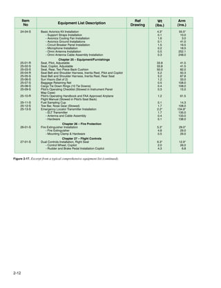
Figure 7-2 is a comprehensive list of all Cessna equipment
that is available for the Model 182S airplane. It should
not be confused with the airplane-specific equipment list.
An airplane-specific list is provided with each individual
airplane at delivery and is typically found at the end of the
Pilot’s Operating Handbook. The following comprehensive
equipment list and the airplane-specific list have a similar
order of listing.
The comprehensive equipment list provides the following
information in column form:
In the Item No column, each item is assigned a coded number.
The first two digits of the code represent the assignment
of an equipment item within the ATA Specification 100
breakdown (Chapter 11 for Placards, Chapter 21 for Air
Conditioning, Chapter 77 for Engine Indicating, etc.). These
assignments also correspond to the Maintenance Manual
chapter breakdown for the airplane. Items receive a unique
sequence number (01, 02, 03, etc.). After the sequence
number (and hyphen), a suffix letter is assigned to identify
an equipment item as required, standard, or optional. Suffix
letters are as follows:
–R = required item or equipment for FAA certificatio
–S = standard equipment item
–O = optional equipment item replacing required or
standard item(s)
–A = optional equipment item that is in addition to
required or standard items
In the Equipment List Description column, each item is
assigned a descriptive name to help identify its function.
In the Ref Drawing column, a drawing number is provided
that corresponds to the item.
Note: Additional equipment must be installed in accordance
with the reference drawing, service bulletin, or a separate
FAA approval.
In the Wt and Arm columns, you find the weight in pounds
and arm in inches of the equipment item.
Notes: Unless otherwise indicated, true values (not net
change values) for the weight and arm are shown. Positive
arms are distances aft of the airplane datum; negative
arms are distances forward of the datum. Asterisks (*) in
the weight and arm column indicate complete assembly
installations. Some major components of the assembly are
listed on the lines immediately following. The sum of these
major components does not necessarily equal the complete
assembly installation.](https://image.slidesharecdn.com/faa-h-8083-1-221129045810-1fcfd0a4/85/FAA-H-8083-1-pdf-62-320.jpg)


![7-7
Figure 7-9. Load conditions for forward adverse-load CG check.
Item Weight (lb) Arm (in) Moment (lb-in) Most forward CG +33.0
67,798.6
5,780.0
5,520.0
79,098.6 +36.6
Airplane (empty)
Pilot
Fuel (minimum)
Total
1,876.0
170.0
115.0
2,161.0
36.14
34.0
48.0
x =
When rear row of seats is occupied, 120 pounds of
baggage or ballast must be carried in forward baggage
compartment. For additional loading instruction,
see Weight and Balance Data.
Figure 7-11. Typical baggage compartment placard.
Figure 7-10. Load conditions for aft adverse-load CG check.
Item Weight (lb) Arm (in) Moment (lb-in) Most Aft CG +46.0
67,798.6
5,780.0
25,449.6
25,160.0
9,700.0
6,960.0
140,848.2 +45.8
Airplane (empty)
Pilot
Fuel (full tanks – 88 gal)
Rear seat occupants (2)
Baggage A
Baggage B
Total
1,876.0
170.0
528.0
340.0
100.0
60.0
3,074.0
36.14
34.0
48.2
74.0
97.0
116.0
x =
move the CG outside of its allowable limits. To determine
this, adverse-loaded CG checks must be performed and
the results noted in the weight and balance revision sheet.
[Figure 7-3]
Forward Adverse-Load CG Check
To conduct a forward CG check, make a chart that includes
the airplane and any occupants and items of the load located
in front of the forward CG limit. Include only those items
behind the forward limit that are essential to flight: the pilot,
and the minimum fuel.
In this example, the pilot, whose nominal weight is 170
pounds, is behind the forward CG limit. The fuel is also
behind the forward limit, so the minimum fuel is used. For
weight and balance purposes, the minimum fuel is no more
than the quantity needed for one-half hour of operation at
rated maximum continuous power. This is considered to
be 1
⁄12 gallon for each maximum except takeoff (METO)
horsepower. Because aviation gasoline weighs 6 pounds per
gallon, determine the number of pounds of the minimum fuel
by dividing the METO horsepower by two. In this example,
minimum fuel is 115 pounds. The front and rear seats and the
baggage are all behind the forward CG limit, so no passengers
or baggage are considered.
Make a chart like the one in Figure 7-9 to determine the CG
with the aircraft loaded for its most forward CG. With the
load consisting of only a pilot and the minimum fuel, the CG
is +36.6, which is behind the most forward allowable limit
for this weight of +33.0.
Aft Adverse-Load CG Check
To conduct an aft or rearward CG check, make a chart that
includes the empty weight and EWCG of the aircraft after
the alteration and all occupants and items of the load behind
the aft CG limit of 46.0. The pilot is in front of this limit but
is essential for flight and must be included. In this example,
only the pilot occupies the front seats. Since the CG of the
fuel is behind the aft limit, full fuel is used, as well as the
nominal weight (170 lb) for both rear seat passengers and
the maximum allowable baggage.
Under these loading conditions, the CG is located at +45.8,
which is ahead of the aft limit of +46.0. [Figure 7-10] With
only the pilot in front of the aft CG limit and maximum of all
items behind the aft limit, the CG is at +45.8 inches, which
is ahead of the aft limit of +46.0 inches.
Ballast
It is possible to load most modern airplanes so the CG
shifts outside of the allowable limit. Placards and loading
instructions in the weight and balance data inform the pilot
of the restrictions that prevent such a shift from occurring.
A typical placard in the baggage compartment of an airplane
is shown in Figure 7-11. When the CG of an aircraft falls
outside of the limits, it can usually be brought back in by
using ballast.](https://image.slidesharecdn.com/faa-h-8083-1-221129045810-1fcfd0a4/85/FAA-H-8083-1-pdf-67-320.jpg)

![8-1
Introduction
Weight and balance considerations of a helicopter are similar
to those of an airplane, except they are far more critical,
and the center of gravity (CG) range is much more limited.
[Figures 8-1 and 8-2] The engineers who design a helicopter
determine the amount of cyclic control authority that is
available, and establish both the longitudinal and lateral CG
envelopes that allow the pilot to load the helicopter so there
is sufficient cyclic control for all flight conditions
Weight and Balance Control—
Helicopter
Chapter 8](https://image.slidesharecdn.com/faa-h-8083-1-221129045810-1fcfd0a4/85/FAA-H-8083-1-pdf-69-320.jpg)


![9-2
Figure 9-1. Determining the distance of CG.
Distance CG to LEMAC Datum to CG – Datum to LEMAC
CG
Distance weight is shifted
=
Figure 9-2. Determining the EWCG in percent MAC.
EWCG in % MAC
CG in inches from LEMAC × 100
MAC
=
Establishing the Initial Weight of an
Aircraft
Prior to being placed into service, each aircraft is weighed
and the empty weight and CG location established. New
aircraft are normally weighed at the factory and are eligible
to be placed into operation without reweighing if the weight
and balance records were adjusted for alterations and
modificationsto the aircraft, such as interior reconfigurations
An aircraft transferred from one operator that has an approved
weight and balance program to another operator with an
approved program does not need to be weighed prior to use by
the receiving operator unless more than 36 calendar months
have elapsed since the last individual or fleet weighing, or
unless some other modification to the aircraft warrants that
the aircraft be weighed. Aircraft transferred, purchased, or
leased from an operator without an approved weight and
balance program, and that have not been modified or have
been minimally modified,can be placed into service without
being reweighed if the last weighing was accomplished by an
acceptable method (for example, manufacturer’s instructions
or AC 43.13-2, Acceptable Methods, Techniques, and
Practices—Aircraft Alterations) within the last 12 calendar
months and a weight and balance change record was
maintained by the operator. It is potentially unsafe to fail to
reweigh an aircraft after it has been modified
When weighing large aircraft, compliance with the relevant
manuals, operations specifications, or management
specification is required to ensure that weight and balance
requirements specified in the Aircraft Flight Manual (AFM)
are met in accordance with approved limits. This provides
information to the flight crew that allows the maximum
payload to be carried safely.
The aircraft should be weighed in still air or an enclosed
building after the aircraft has been cleaned. Ensure that the
aircraft is in a configuration for weighing with regard to
flightcontrols, unusable fuel, ballast, oil and other operating
fluids, and equipment as required by the controlling weight
and balance procedure.
Large aircraft are not usually raised off the floor on jacks
for weighing; they are weighed on ramp-type scales. The
scales must be properly calibrated, zeroed, and used in
accordance with the manufacturer’s instructions. Each scale
should be periodically checked for accuracy as recommended
in the manufacturer’s calibration schedule, either by the
manufacturer or by a recognized facility, such as a civil
department of weights and measures. If no manufacturer’s
schedule is available, the period between calibrations should
not exceed 12 months.
Determining the Empty Weight and
Empty Weight CG (EWCG)
When the aircraft is properly prepared for weighing, roll it
onto the scales, and level it. The weights are measured at
three weighing points: the two main wheel points and the
nosewheel point. The empty weight and empty weight CG
(EWCG) are determined by using the following steps with
the results recorded in the weight and balance record for use
in all future weight and balance computations.
1. Determine the moment index of each of the main-
wheel points by multiplying the net weight (scale
reading minus tare weight), in pounds, at these points
by the distance from the datum, in inches. Divide these
numbers by the appropriate reduction factor.
2. Determine the moment index of the nosewheel
weighing point by multiplying its net weight, in
pounds, by its distance from the datum, in inches.
Divide this by the reduction factor.
3. Determine the total weight by adding the net weight of
the three weighing points and the total moment index
by adding the moment indexes of each point.
4. Divide the total moment index by the total weight and
multiply the result by the reduction factor. This gives
the CG in inches from the datum.
5. Determine the distance of the CG behind the leading
edge of the mean aerodynamic chord (LEMAC)
by subtracting the distance between the datum and
LEMAC from the distance between the datum and
the CG. [Figure 9-1]
6. Determine the EWCG in percentage of MAC (percent
MAC) by using the formula in Figure 9-2.](https://image.slidesharecdn.com/faa-h-8083-1-221129045810-1fcfd0a4/85/FAA-H-8083-1-pdf-74-320.jpg)


![9-5
Figure 9-6. Determining the location of the CG in inches aft of
the datum.
( )
CG inches aft of datum = × 1,000
Total moment index
Total weight
( )
= × 1,000
161,646
177,710
= 909.6 inches
Figure 9-7. Determining the distance from the CG to the LEMAC.
Distance CG to LEMAC = Datum to CG – Datum to LEMAC
= 49.1 inches
= 909.6 – 860.5
Figure 9-8. Determining the location of the CG in percent MAC.
( )
CG % MAC = × 100
Distance CG to LEMAC
MAC
( )
= × 100
49.1
180.9
= 27.1%
Determine the distance from the CG to the LEMAC by
subtracting the distance between the datum and LEMAC from
the distance between the datum and the CG. [Figure 9-7]
The location of the CG in percent MAC must be known in
order to set the stabilizer trim takeoff. [Figure 9-8]
Operational Empty Weight (OEW)
Operational empty weight (OEW) is the basic empty weight
or fl et empty weight plus operational items. The operator has
two choices for maintaining OEW. The loading schedule may
be utilized to compute the operational weight and balance of
an individual aircraft, or the operator may choose to establish
fleet empty weights for a fleet or group of aircraf
Reestablishing the OEW
The OEW and CG position of each aircraft should be
reestablished at the reweighing. In addition, it should be
reestablished through calculation whenever the cumulative
change to the weight and balance log is more than plus or
minus one-half of 1 percent (0.5 percent) of the maximum
landing weight, or whenever the cumulative change in the
CG position exceeds one-half of 1 percent (0.5 percent) of the
MAC. In the case of rotorcraft and aircraft that do not have a
MAC-based CG envelope (e.g., canard equipped airplane),
whenever the cumulative change in the CG position exceeds
one-half of 1 percent (0.5 percent) of the total CG range, the
weight and balance should be reestablished.
When reestablishing the aircraft OEW between reweighing
periods, the weight changes may be computed provided the
weight and CG location of the modifications are known;
otherwise, the aircraft must be reweighed.
Fleet Operating Empty Weights (FOEW)
An operator may choose to use one weight for a fleetor group
of aircraft if the weight and CG of each aircraft is within the
limits stated above for establishment of OEW. When the
cumulative changes to an aircraft weight and balance log
exceed the weight or CG limits for the established fleetweight,
the empty weight for that aircraft should be reestablished.
This may be done by moving the aircraft to another group, or
reestablishing new fleet operating empty weights (FOEWs)
Onboard Aircraft Weighing System
Some large transport airplanes have an onboard aircraft
weighing system (OBAWS) that, when the aircraft is on the
ground, gives the flight crew a continuous indication of the
aircraft total weight and the location of the CG in percent
MAC. Procedures are required to ensure the onboard weight
and balance system equipment is periodically calibrated in
accordance with the manufacturer’s instructions.
An operator may use an onboard weight and balance
system to measure an aircraft’s weight and balance as a
primary means to dispatch an aircraft, provided the FAA
has certified the system and approved the system for use in
an operator’s weight and balance control program. As part
of the approval process, the onboard weight and balance
system must maintain its certificatedaccuracy. The accuracy
demonstration test is provided in the maintenance manual
portion of the Supplemental Type Certificate (STC) or type
certificate of the onboard weight and balance system.
The system consists of strain-sensing transducers in each
main wheel and nosewheel axle, a weight and balance
computer, and indicators that show the gross weight, the
CG location in percent MAC, and an indicator of the ground
attitude of the aircraft.
The strain sensors measure the amount each axle defl cts and
sends this data into the computer, where signals from all of
the transducers and the ground attitude sensor are integrated.
The results are displayed on the indicators for the flightcrew.
Using an onboard weight and balance system does not relieve
an operator from the requirement to complete and maintain
a load manifest.](https://image.slidesharecdn.com/faa-h-8083-1-221129045810-1fcfd0a4/85/FAA-H-8083-1-pdf-77-320.jpg)
![9-6
Figure 9-9. Stabilizer trim setting in ANU units.
Stabilizer Trim Setting—Units Airplane Nose Up
6
8
10
12
14
16
18
20
22
24
26
28
30
32
8
73/4
71/2
7
63/4
61/4
53/4
51/2
5
41/2
4
31/2
3
21/2
Flaps (all)
CG
Figure 9-10. Determining the distance from CG to the LEMAC.
Distance CG to LEMAC = Datum to CG – Datum to LEMAC
= 10.7 inches
= 635.7 – 625
Figure 9-11. Determining the location of CG in percent MAC.
( )
CG in % MAC = × 100
Distance CG to LEMAC
MAC
( )
= × 100
10.7
134.0
= 8.0 % MAC
Figure 9-12. Determining the location of CG in inches before cargo
is removed.
( )
CG (inches aft of LEMAC) = × MAC
CG in % MAC
100
( )
= × 141.5
22.5
100
= 31.84 inches
Determining the Correct Stabilizer Trim Setting
It is important before takeoff to set the stabilizer trim for the
existing CG location. There are two ways the stabilizer trim
setting systems may be calibrated: in percent MAC and in
units airplane nose up (ANU).
If the stabilizer trim is calibrated in percent MAC, determine
the CG location in percent MAC as has just been described,
then set the stabilizer trim on the percentage figure thus
determined. Some aircraft give the stabilizer trim setting in
units of ANU that correspond with the location of the CG
in percent MAC. When preparing for takeoff in an aircraft
equipped with this system, first determine the CG in percent
MAC in the way described above, then refer to the stabilizer
trim setting chart on the takeoff performance page of the
pertinent AFM. Figure 9-9 is an excerpt from the AFM chart
on the takeoff performance of a Boeing 737.
Consider an airplane with these specifications
CG location................................................. station 635.7
LEMAC......................................................... station 625
MAC...................................................................134.0 in
1. Determine the distance from the CG to the LEMAC
by using the formula in Figure 9-10.
2. Determine the location of the CG in percent MAC by
using the formula found in Figure 9-11.
Refer to Figure 9-9 for all flap settings and a CG located
at 8 percent MAC; the stabilizer setting is 73
⁄4 units ANU.
Determining CG Changes Caused by
Modifying the Cargo
Since large aircraft can carry substantial cargo, adding,
subtracting, or moving any of the cargo from one hold to
another can cause large shifts in the CG.
Effects of Loading or Offloading Cargo
Both the weight and CG of an aircraft are changed when
cargo is loaded or offloaded. In the following example, the
new weight and CG are calculated after 2,500 pounds of
cargo is offloaded from the forward cargo hold
Aircraft specifications are
Loaded weight..................................................90,000 lb
Loaded CG.
........................................ 22.5 percent MAC
Weight change....................................................2,500 lb
Forward cargo hold centroid.
...................... station 352.1
MAC...................................................................141.5 in
LEMAC.................................................... station 549.13
1. Determine the CG location in inches from the
datum before the cargo is removed. Do this by first
determining the distance of the CG aft of the LEMAC.
[Figure 9-12]](https://image.slidesharecdn.com/faa-h-8083-1-221129045810-1fcfd0a4/85/FAA-H-8083-1-pdf-78-320.jpg)
![9-7
Figure 9-13. Determining the distance between CG and the datum.
CG (inches from datum) = CG inches aft of LEMAC
+ Datum to LEMAC
= 580.97 inches
= 31.84 + 549.13
Figure 9-14. Determining the moment/1,000 for the original weight.
Moment/1,000 = Weight × Arm
1,000
90,000 × 580.97
1,000
= 52,287.3
=
Figure 9-15. Determining the moment/1,000 of the removed weight.
Moment/1,000 = Weight × Arm
1,000
2,500 × 352.1
1,000
= 880.25
=
Figure 9-16. New weights and CG.
Weight (lb) Moment/1,000 CG (inches from datum) CG (percent MAC)
580.97
587.51
22.5
27.12
Original data
Changes
New data
90,000
– 2,500
87,500
52,287.3
– 880.3
51,407.0
Figure 9-17. Determining the location of new CG.
CG = × 1,000
Total moment/1,000
Total weight
51,407.0
87,500
= × 1,000
= 587.51 inches behind the datum
Figure 9-18. Determining the distance between the CG and LEMAC.
CG (inches aft of LEMAC) =
CG (inches from datum) – LEMAC
= 38.38 inches
= 587.51 – 549.13
Figure 9-19. Determining the new CG in percent MAC.
( )
CG % MAC = × 100
Distance CG to LEMA
MAC
( )
= × 100
38.38
141.5
= 27.12% MAC
2. Determine the distance between the CG and the datum
by adding the CG in inches aft of LEMAC to the
distance from the datum to LEMAC. [Figure 9-13]
3. Determine the moment/1,000 for the original weight.
[Figure 9-14]
4. Determine the new weight and new CG by first
determining the moment/1,000 of the removed weight.
Multiply the weight removed (2,500 pounds) by the
centroid of the forward cargo hold (352.1 inches), and
then divide the result by 1,000. [Figure 9-15]
5. Subtract the removed weight from the original weight
and subtract the moment/1,000 of the removed weight
from the original moment/1,000. [Figure 9-16]
6. Determine the location of the new CG by dividing
the total moment/1,000 by the total weight and
multiplying this by the reduction factor of 1,000.
[Figure 9-17]
7. Convert the new CG location to percent MAC. First,
determine the distance between the CG location and
LEMAC. [Figure 9-18]
8. Then, determine the new CG in percent MAC.
[Figure 9-19]
Loading 3,000 pounds of cargo into the forward cargo hold
moves the CG forward 5.51 inches, from 27.12 percent MAC
to 21.59 percent MAC.](https://image.slidesharecdn.com/faa-h-8083-1-221129045810-1fcfd0a4/85/FAA-H-8083-1-pdf-79-320.jpg)
![9-8
Figure 9-24. Determining the change in CG caused by shifting
2,500 pounds of cargo.
CG = × 100
Weight shifted × Distance shifted
Total weight
=
2,500 × (227.9 + 144.9)
90,000
= 2,500 × 372.8
90,000
= 10.36 inches
Figure 9-21. Determining the new CG after shifting cargo weight.
New CG = Old CG ± CG
= 591.33 inches
= 580.97 + 10.36
Figure 9-22. Converting the location of CG to percent MAC.
( )
CG % MAC = × 100
CG inches
MAC
( )
= × 100
10.36
141.5
= 7.32% MAC
Figure 9-23. Determining the new CG in percent MAC.
New CG % MAC = Old CG ± CG
= 29.82% MAC
= 22.5% + 7.32%
Figure 9-20. Calculating the change in CG, using index arms.
CG = Weight shifted × Distance shifted
Total weight
=
2,500 × (724.9 – 352)
90,000
= 2,500 × 372.9
90,000
= 10.36 inches
Effects of Shifting Cargo From One Hold to
Another
When cargo is shifted from one cargo hold to another, the CG
changes, but the total weight of the aircraft remains the same.
For example, use the following data:
Loaded weight................................................. 90,000 lb
Loaded CG.
............. station 580.97 (22.5 percent MAC)
Forward cargo hold centroid.
........................ station 352
Aft cargo hold centroid.............................. station 724.9
MAC...................................................................141.5 in
LEMAC........................................................ station 549
To determine the change in CG (∆CG) caused by shifting
2,500 pounds of cargo from the forward cargo hold to the
aft cargo hold, use the formula in Figure 9-20.
Since the weight was shifted aft, the CG moved aft and the
CG change is positive. If the shift were forward, the CG
change would be negative.
Before the cargo was shifted, the CG was located at station
580.97, which is 22.5 percent of MAC. The CG moved aft
10.36 inches, so the new CG is found using the formula from
Figure 9-21.
Convert the location of the CG in inches aft of the datum to
percent MAC by using the formula in Figure 9-22.
The new CG in percent MAC caused by shifting the cargo is
the sum of the old CG plus the change in CG. [Figure 9-23]
Some AFMs locate the CG relative to an index point rather
than the datum or the MAC. An index point is a location
specifiedby the aircraft manufacturer from which arms used
in weight and balance computations are measured. Arms
measured from the index point are called index arms, and
objects ahead of the index point have negative index arms,
while those behind the index point have positive index arms.
Use the same data as in the previous example, except for
these changes:
Loaded CG.
.......................... index arm of 0.97, which is
22.5 percent of MAC
Index point.................................... fuselage station 580.0
Forward cargo hold centroid.
...............–227.9 index arm
Aft cargo hold centroid........................+144.9 index arm
MAC...................................................................141.5 in
LEMAC...............................................–30.87 index arm
The weight was shifted 372.8 inches (–227.9 + Δ = +144.9,
Δ =372.8).
The change in CG can be calculated by using this formula
found in Figure 9-24.](https://image.slidesharecdn.com/faa-h-8083-1-221129045810-1fcfd0a4/85/FAA-H-8083-1-pdf-80-320.jpg)
![9-9
Figure 9-25. Determining the new CG, moved aft 10.36 inches.
New CG = Old CG ± CG
= 11.33 index arm
= 0.97 + 10.36
Figure 9-26. The change in the CG in percent MAC.
New CG % MAC = Old CG ± CG
= 29.82% MAC
= 22.5% + 7.32%
Figure 9-27. The new CG in percent MAC.
( )
CG % MAC = × 100
CG inches
MAC
( )
= × 100
10.36
141.5
= 7.32% MAC
Figure 9-28. Determining pallet area in square feet.
Area (sq. ft.) = Length (inches) × Width (inches)
144 square inches/square foot
=
48.5 × 33.5
144
= 1,624.7
144
= 11.28 square feet
Since the weight was shifted aft, the CG moved aft, and the
CG change is positive. If the shift were forward, the CG
change would be negative. Before the cargo was shifted,
the CG was located at 0.97 index arm, which is 22.5 percent
MAC. The CG moved aft 10.36 inches, and the new CG is
shown using the formula in Figure 9-25.
The change in the CG in percent MAC is determined by using
the formula in Figure 9-26.
The new CG in percent MAC is the sum of the old CG plus
the change in CG. [Figure 9-27]
Notice that the new CG is in the same location whether the
distances are measured from the datum or from the index
point.
Determining Cargo Pallet Loads and Floor
Loading Limits
Each cargo hold has a structural floor loading limit based on
the weight of the load and the area over which this weight is
distributed. To determine the maximum weight of a loaded
cargo pallet that can be carried in a cargo hold, divide its total
weight, which includes the weight of the empty pallet and
its tie down devices, by its area in square feet. This load per
square foot must be equal to or less than the floor load limit.
In this example, determine the maximum load that can be
placed on this pallet without exceeding the floorloading limit.
Pallet dimensions...........................................36 by 48 in
Empty pallet weight.................................................47 lb
Tie down devices.....................................................33 lb
Floor load limit.............................169 lb per square foot
The pallet has an area of 36 inches (3 feet) by 48 inches
(4 feet), which equals 12 square feet, and the floor has a
load limit of 169 pounds per square foot. Therefore, the total
weight of the loaded pallet can be 169 × 12 = 2,028 pounds.
Subtracting the weight of the pallet and the tie down devices
gives an allowable load of 1,948 pounds (2,028 – [47 + 33]).
Determine the floor loading limit that is needed to carry a
loaded cargo pallet having the following dimensions and
weights:
Pallet dimensions ....................................48.5 by 33.5 in
Pallet weight ...........................................................44 lb
Tiedown devices .....................................................27 lb
Cargo weight .
.....................................................786.5 lb
First, determine the number of square feet of pallet area as
shown in Figure 9-28.
Then, determine the total weight of the loaded pallet:
Pallet.....................................................................44.0 lb
Tiedown devices ..................................................27.0 lb
Cargo..................................................................786.5 lb
Total....................................................................857.5 lb
Determine the load imposed on the floorby the loaded pallet.
[Figure 9-29] The floor must have a minimum loading limit
of 76 pounds per square foot.](https://image.slidesharecdn.com/faa-h-8083-1-221129045810-1fcfd0a4/85/FAA-H-8083-1-pdf-81-320.jpg)
![9-10
Figure 9-29. Determining the load imposed on the floor by the
loaded pallet.
Floor Load = Loaded weight
Pallet area
857.5
11.28
= 76.0 pounds/square foot
=
Figure 9-30. Finding the maximum takeoff weight.
Max limit
142,000
184,200
Landing weight
+ trip fuel
Takeoff weight
Trip limit
142,000
+ 40,000
182,000
Figure 9-31. Determining zero fuel weight with lower trip limits.
Max limit
184,200
138,000
Landing weight
– fuel load
Zero fuel weight
Trip limit
182,000
– 54,000
128,000
Figure 9-32. Finding maximum payload with lower trip limits.
Max limit
138,000 Zero fuel weight
– BOW
Payload (pounds)
Trip limit
128,000
–100,500
27,500
Determining the Maximum Amount of Payload
That Can Be Carried
The primary function of a transport or cargo aircraft is to carry
payload, which is the portion of the useful load, passengers,
or cargo that produces revenue. To determine the maximum
amount of payload that can be carried, both the maximum
limits for the aircraft and the trip limits imposed by the
particular trip must be considered. In each of the following
steps, the trip limit must be less than the maximum limit. If
it is not, the maximum limit must be used.
These are the specifications for the aircraft in this example
Basic operating weight (BOW)......................100,500 lb
Maximum zero fuel weight.
............................138,000 lb
Maximum landing weight.
..............................142,000 lb
Maximum takeoff weight...............................184,200 lb
Fuel tank load ..................................................54,000 lb
Estimated fuel burn en route.
............................40,000 lb
1. Compute the maximum takeoff weight for this trip.
This is the maximum landing weight plus the trip fuel.
[Figure 9-30]
2. The trip limit is lower than the maximum takeoff
weight, so it is used to determine the zero fuel weight.
[Figure 9-31]
3. The trip limit is again lower than the maximum takeoff
weight, so use it to compute the maximum payload
for this trip. [Figure 9-32]
Under these conditions, 27,500 pounds of payload may be
carried.
Determining the Landing Weight
It is important to know the landing weight of the aircraft in
order to set up the landing parameters and to be certain the
aircraft is able to land safely at the intended destination.
In this example of a four-engine turboprop airplane,
determine the airplane weight at the end of 4.0 hours of cruise
under these conditions:
Takeoff weight.
...............................................140,000 lb
Pressure altitude during cruise.
..........................16,000 ft
Ambient temperature during cruise......................–32 °C
Fuel burned during descent and landing.............1,350 lb
Refer to the U.S. Standard Atmosphere Table in
Figure 9-33 and the gross weight table in Figure 9-34 when
completing the following steps:
1. Use the U.S. Standard Atmosphere Table to
determine the standard temperature for 16,000 feet
(–16.7 °C).
2. The ambient temperature is –32 °C, which is a
deviation from standard of 15.3 °C. (–32° – (–16.7°)
= –15.3°). It is below standard.
3. In the gross weight table, follow the vertical line
representing 140,000 pounds gross weight upward
until it intersects the diagonal line for 16,000 feet
pressure altitude.
4. From this intersection, draw a horizontal line to the left
to the temperature deviation index (0 °C deviation).
5. Draw a diagonal line parallel to the dashed lines for
Below Standard from the intersection of the horizontal
line and the Temperature Deviation Index.
6. Draw a vertical line upward from the 15.3 °C
Temperature Deviation From Standard.](https://image.slidesharecdn.com/faa-h-8083-1-221129045810-1fcfd0a4/85/FAA-H-8083-1-pdf-82-320.jpg)

![9-12
Figure 9-36. Determining the amount of weight the aircraft must
lose to reach the maximum allowable landing weight.
171,000 lb cruise weight
– 142,500 lb maximum landing weight
28,500 lb required reduction
Figure 9-37. Determining the amount of fuel burned from the
beginning of the dump to touchdown.
Fuel flow = 3,170 lb/hr/engine
60
= 52.83 lb/min engine
Figure 9-38. Determining the amount of fuel needed to dump.
28,500.00 lb required weight reduction
– 2,007.54 lb fuel burned after start of dumping
26,492.46 lb fuel to be dumped
Figure 9-39. Determine the time needed to dump fuel.
= 11.52 minutes
26,492.46
2,300
Determining Fuel Dump Time in Minutes
Most large aircraft are approved for a greater weight for
takeoff than for landing. To make it possible for them to
return to landing soon after takeoff, a fuel jettison system is
sometimes installed. It is important in an emergency situation
that the flight crew be able to dump enough fuel to lower the
weight to its allowed landing weight. This is done by timing
the dumping process.
In this example, the aircraft has two engines operating and
these specifications apply
Cruise weight..................................................171,000 lb
Maximum landing weight.
..............................142,500 lb
Time from start of dump to landing.
.............. 19 minutes
Average fuel flow during
Dumping and descent..............................3,170 lb/hr/eng
Fuel dump rate........................................2,300 lb/minute
To calculate the fuel dump time in minutes:
1. Determine the amount of weight the aircraft must
lose to reach the maximum allowable landing weight.
[Figure 9-36]
2. Determine the amount of fuel burned from the
beginning of the dump to touchdown. [Figure 9-37]
For both engines, this is 52.83 × 2 = 105.66 lb/minute.
The engines burn 105.66 lbs of fuel per min for 19 minutes
(the duration of the dump), which calculates to 2007.54
pounds of fuel burned between the beginning of the dump
and touchdown.
3. Determine the amount of fuel needed to dump by
subtracting the amount of fuel burned during the dump
from the required weight reduction. [Figure 9-38]
4. Determine the time needed to dump this amount of
fuel by dividing the number of pounds of fuel to dump
by the dump rate. [Figure 9-39]
Weight and Balance of Commuter Category
Airplanes
The Beech 1900 is a typical commuter category airplane that
can be configured to carry passengers or cargo. Figure 9-40
shows the loading data of this type of airplane in the
passenger configuration
Determining the Loaded Weight and CG
As this airplane is prepared for flight,a manifest is prepared.
[Figure 9-41]](https://image.slidesharecdn.com/faa-h-8083-1-221129045810-1fcfd0a4/85/FAA-H-8083-1-pdf-84-320.jpg)

![9-14
Figure 9-42. Weight and moments—occupants.
Weight
Moment/100
80
90
100
110
120
130
140
150
160
170
180
190
200
210
220
230
240
250
103
116
129
142
155
168
181
194
206
219
232
245
258
271
284
297
310
323
160
180
200
220
240
260
280
300
320
340
360
380
400
420
440
460
480
500
184
207
230
253
276
299
322
345
368
391
414
437
460
483
506
529
552
575
208
234
260
286
312
338
364
390
416
442
468
494
520
546
572
598
624
650
232
261
290
319
348
377
406
435
464
493
522
551
680
609
638
667
696
725
256
288
320
352
384
416
448
480
512
544
576
608
640
672
704
736
768
800
280
315
350
385
420
455
490
525
560
595
630
665
700
735
770
805
840
875
304
342
380
418
456
494
532
570
608
646
684
722
760
798
836
874
912
950
328
369
410
451
492
533
574
615
656
697
738
779
820
861
902
943
984
1025
352
396
440
484
528
572
616
660
704
748
792
836
880
924
968
1012
1056
1100
Useful Load Weights and Moments—Occupants
Crew Cabin seats
F.S.
129
F.S.
200
F.S.
230
F.S.
260
F.S.
290
F.S.
320
F.S.
350
F.S.
380
F.S.
410
F.S.
440
Figure 9-43. Weight and moments—baggage.
Weight
10
20
30
40
50
60
70
80
90
100
150
200
250
300
350
400
450
500
550
600
630
650
700
750
800
850
880
7
13
20
26
33
39
46
52
59
66
98
16
33
49
65
82
98
115
131
147
164
245
327
409
48
97
145
193
242
290
338
387
435
484
725
967
1209
1450
1692
1934
2176
2418
2659
2901
3046
3143
3384
3626
3868
4110
4255
53
107
160
213
266
320
373
426
480
533
800
1066
1332
1599
1866
2132
2398
2665
2932
3198
3358
Moment/100
Useful Load Weights and Moments—Baggage
Nose
baggage
compartment
F.S. 65.5
Forward
cabin
baggage
compartment
F.S. 163.6
AFT baggage/
cargo
compartment
(Forward
section)
F.S. 483.5
AFT baggage/
cargo
compartment
(Aft
section)
F.S. 533.0
Figure 9-44. Density variation of aviation fuel.
−40 −30 −20 −10 0 10 20 30 40
7.5
7.0
6.5
6.0
5.5
Aviation kerosene jet A & Jet A1
Jet B (JP-4)
Aviation gasoline grade 100/130
NOTE: The fuel quantity indicator
is calibrated for correct indication
when using aviation kerosene jet
A and jet A1. When using other
fuels, multiply the indicated fuel
quantity in pounds by 0.99 for jet
B (JP-4) or by aviation gasoline
(100/130) to obtain actual fuel
quantity in pounds.
Aviation
kerosene
Jet A and
Jet A1 0.812
Jet B (JP-4) 0.785
AV gas grade
100/130 0.703
Average
specific
gravity
at 15 °C
(59 °F)
Fuel
Specific
weight
(lb/US
gal)
Temperature (°C)
1. The crew weight and the weight of each passenger is
entered into the manifest. The moment/100 for each
occupant is determined by multiplying the weight by
the arm and dividing by 100. This data is available in
the AFM and is shown in the Weight and Moments—
Occupants table. [Figure 9-42]
2. The weight of the baggage in each compartment used
is entered with its moment/100. This is determined
in the Weights and Moments—Baggage table.
[Figure 9-43]
3. Determine the weight of the fuel. Jet A fuel has
a nominal specific gravity at +15 °C of 0.812
and weighs 6.8 pounds per gallon, but at +25 °C,
according to the Density Variation of Aviation Fuel
Chart [Figure 9-44], it weighs 6.75 lb/gal. Using this](https://image.slidesharecdn.com/faa-h-8083-1-221129045810-1fcfd0a4/85/FAA-H-8083-1-pdf-86-320.jpg)
![9-15
Figure 9-45. Weights and moments—usable fuel.
Gallons
Weight
Moment
100
6.5 lb/gal
Weight
Moment
100
6.6 lb/gal
Weight
Moment
100
6.7 lb/gal
Weight
Moment
100
6.8 lb/gal
10
20
30
40
50
60
70
80
90
100
110
120
130
140
150
160
170
180
190
200
210
220
230
240
250
260
270
280
290
300
310
320
330
340
350
360
370
380
390
400
410
420
425
65
130
195
260
325
390
455
520
585
650
715
780
845
910
975
1,040
1,106
1,170
1,235
1,300
1,365
1,430
1,495
1,560
1,625
1,690
1,755
1,820
1,885
1,950
2,015
2,080
2,145
2,210
2,275
2,340
2,405
2,470
2,535
2,600
2,665
2,730
2,763
197
394
592
789
987
1,185
1,383
1,581
1,779
1,977
2,175
2,372
2,569
2,765
2,962
3,157
3,351
3,545
3,739
3,932
4,124
4,315
4,507
4,698
4,889
5,080
5,271
5,462
5,651
5,842
6,032
6,225
6,417
6,610
6,802
6,995
7,188
7,381
7,575
7,768
7,962
8,156
8,259
66
132
198
264
330
396
462
528
594
660
726
792
858
924
990
1,056
1,122
1,188
1,254
1,320
1,386
1,452
1,518
1,584
1,650
1,716
1,782
1,848
1,914
1,980
2,046
2,112
1,278
2,244
2,310
2,376
2,442
2,508
2,574
2,640
2,706
2,772
2,805
200
401
601
802
1,002
1,203
1,404
1,605
1,806
2,007
2,208
2,409
2,608
2,808
3,007
3,205
3,403
3,600
3,797
3,992
4,187
4,382
4,576
4,770
4,964
5,158
5,352
5,546
5,738
5,932
6,125
6,321
6,516
6,711
6,907
7,103
7,299
7,495
7,691
7,888
8,085
8,282
8,386
67
134
201
268
335
402
469
536
603
670
737
804
871
938
1,005
1,072
1,139
1,206
1,273
1,340
1,407
1,474
1,541
1,608
1,675
1,742
1,809
1,876
1,943
2,010
2,077
2,144
2,211
2,278
2,345
2,412
2,479
2,546
2,613
2,680
2,747
2,814
2,848
203
407
610
814
1,018
1,222
1,426
1,630
1,834
2,038
2,242
2,445
2,648
2,850
3,053
3,254
3,454
3,654
3,854
4,053
4,250
4,448
4,646
4,843
5,040
5,236
5,433
5,630
5,825
6,022
6,218
6,416
6,615
6,813
7,011
7,210
7,409
7,609
7,808
8,007
8,207
8,407
8,513
68
136
204
272
340
408
476
544
612
680
748
816
884
952
1,020
1,088
1,156
1,224
1,292
1,360
1,428
1,496
1,564
1,632
1,700
1,768
1,836
1,904
1,972
2,040
2,108
2,176
2,244
2,312
2,380
2,448
2,516
2,584
2,652
2,720
2,788
2,856
2,890
206
413
619
826
1,033
1,240
1,447
1,654
1,861
2,068
2,275
2,482
2,687
2,893
3,099
3,303
3,506
3,709
3,912
4,113
4,314
4,514
4,715
4,915
5,115
5,315
5,514
5,714
5,912
6,112
6,311
6,512
6,713
6,915
7,116
7,318
7,520
7,722
7,924
8,127
8,330
8,532
8,640
Useful Load Weights and Moments—Usable Fuel
chart, determine the weights and moment/100 for 390
gallons of Jet A fuel by interpolating between those
for 6.7 lb/gal and 6.8 lb/gal. The 390 gallons of fuel at
this temperature weighs 2,633 pounds, and its moment
index is 7,866 lb-in/100.
4. Add all of the weights and all of the moment indexes.
Divide the total moment index by the total weight, and
multiply this by the reduction factor of 100. The total
weight is 14,729 pounds; the total moment index is
43,139 lb-in/100. The CG is located at fuselage station
292.9. [Figure 9-45]
5. Check to determine that the CG is within limits for
this weight. Refer to the Weight and Balance Diagram.
[Figure 9-46] Draw a horizontal line across the
envelope at 14,729 pounds of weight and a vertical
line from the CG of 292.9 inches aft of the datum.
These lines cross inside the envelope, verifying the
CG is within limits for this weight.](https://image.slidesharecdn.com/faa-h-8083-1-221129045810-1fcfd0a4/85/FAA-H-8083-1-pdf-87-320.jpg)
![9-16
Figure 9-46. Weight and balance diagram.
17,000
16,000
15,000
14,000
13,000
12,000
11,000
10,000
9,000
272 276 280 284 288 292 296 300 304
CG (inches aft of datum)
W
e
ig
h
t
(
lb
)
Maximum zero fuel weight
Maximum takeoff weight 16,600
Maximum landing weight 16,000
Maximum zero fuel weight 14,000
Maximum takeoff weight
Determining the Changes in CG When
Passengers Are Shifted
Using the loaded weight and CG of the Beech 1900, calculate
the change in CG when the passengers in rows 1 and 2 are
moved to rows 8 and 9. [Figure 9-47] Note that there is no
weight change, but the moment index has been increased by
1,155 pound-inches/100 to 44,294. The new CG is at fuselage
station 300.7. [Figure 9-48]
This type of problem is usually solved by using the following
two formulas. The total amount of weight shifted is 550
pounds (300 + 250) and both rows of passengers have moved
aft by 210 inches (410 – 200 and 440 – 230). The CG has
been shifted aft by 7.8 inches, and the new CG is at station
300.7. [Figure 9-49]](https://image.slidesharecdn.com/faa-h-8083-1-221129045810-1fcfd0a4/85/FAA-H-8083-1-pdf-88-320.jpg)
![9-17
Figure 9-47. Changes in CG caused by shifting passenger seats.
Item Weight Arm Moment/100 CG
(−) 600
(−) 575
(+) 1,230
(+) 1,100
43,139
(+) 1,155
44,294 300.7
Row 1
Row 2
Row 8
Row 9
Original conditions
Changes
New conditions
(−) 300
(−) 250
(+) 300
(+) 250
14,729
0
14,729
200
230
410
440
Figure 9-48. Determining the new CG at fuselage station.
( )
CG = × 100
43,139 + 1,155
14,729
= 300.7
Figure 9-49. Determining the new CG at station after CG has
shifted aft.
CG = Weight shifted × Distance shifted
Total weight
= 550 × 210
14,729
= 7.8 inches
= 292.9 + 7.8
CG = Original CG + CG
= 300.7 inches aft of datum
Figure 9-50. One passenger configuration of a B737-800.
Mixed class:
12 first class seats at 36-inch pitch
148 economy class seats at 32-inch pitch
G
C
C
G
A
A
G
L
G
A
A
L
A
In a large cabin aircraft with high-density seating such as
the B737-800, the operator must account for the seating of
passengers in the cabin [Figure 9-50]. If assigned seating
is used to determine passenger location, the operator
must implement procedures to ensure the assignment of
passenger seating is incorporated into the loading procedure.
It is recommended that the operator take into account the
possibility that some passengers may not sit in their assigned
seats.
If the actual seating location of each passenger is not known,
the operator may assume that all passengers are seated
uniformly throughout the cabin or a specified subsection of
the cabin. Reasonable assumptions can be made about the
manner in which people distribute themselves throughout
the cabin. For example, window seats are occupied first
followed by aisle seats, followed by the remaining seats
(window-aisle-remaining seating). Both forward and rear
loading conditions should be considered. The passengers may
fill up the window, aisle, and remaining seats from the front
of the aircraft to the back, or the back to the front.
If necessary, the operator may divide the passenger cabin
into subsections or zones and manage the loading of each
zone individually. It can be assumed that passengers will be
sitting uniformly throughout each zone.
Another consideration is the inflightmovement of passengers,
crew, and equipment. It is assumed that all passengers, crew,
and equipment are secured when the aircraft is in the takeoff
or landing configuration. Standard operating procedures](https://image.slidesharecdn.com/faa-h-8083-1-221129045810-1fcfd0a4/85/FAA-H-8083-1-pdf-89-320.jpg)
![9-18
Figure 9-51. Loading data for cargo configuration.
Section A
Section B
Section C
Section D
Section E
Section F
Section G
Section H
Section I
Section K
Sec
J
F.S. 210
F.S. 240
F.S. 270
F.S. 300
F.S. 330
F.S. 360
F.S. 390
F.S. 420
F.S. 480
F.S. 513.5
F.S. 450
A 600 F.S. 225.0
B 600 F.S. 255.0
C 600 F.S. 285.0
D 600 F.S. 315.0
E 600 F.S. 345.0
F 600 F.S. 375.0
G 600 F.S. 405.0
H 600 F.S. 435.0
I 600 F.S. 465.0
J 250 F.S. 499.5
K 565 F.S. 533.0
Section
Notes:
1. All cargo in sections A
through J must be
supported on the seat
tracks and secured to the
seat tracks and side seat
rails by an FAA-approved
system.
2. Concentrated cargo loads
in sections A through L
must not exceed 100 lb
per square foot.
3. Cargo in sections K and L
must be retained by
baggage webs and
partitions provided as part
of standard airplane.
4. Any exception to the
above procedures
requires approval by a local
FAA office.
Centroid
arm
Maximum
structural
capacity
Loading cargo configuration
should be taken into account. Examples of items that can
move during flight are:
• Flight deck crew members moving to the lavatory.
• Flight attendants moving throughout the cabin.
• Service carts moving throughout the cabin.
• Passengers moving throughout the cabin.
• Passengers moving to the lavatory.
Determining Changes in Weight and CG
When the Aircraft Is Operated in Its Cargo
Configuratio
To determine changes in weight and CG when the aircraft
is operated in its cargo configuration, the Beech 1900 is
used as an example. Figure 9-51 illustrates the airplane
configuration. Notice that the arm of each cargo section is
the centroid of that section.
The flight manifest of the Beech 1900 in the cargo
confi uration is illustrated in Figure 9-52. The BOW includes
the pilots and their baggage and there is no separate item
for them.
At the standard temperature of 15 °C, the fuel weighs 6.8
pounds per gallon. Refer to Figure 9-45 to determine the
weight and moment index of 370 gallons of Jet A fuel. The
CG under these loading conditions is located at station 296.2.
Determining the CG Shift When Cargo Is Moved
From One Section to Another
To calculate the CG when cargo is shifted from one section
to another, use the formula found in Figure 9-53. If the cargo
is moved forward, the CG is subtracted from the original CG.
If the cargo is shifted aft, add the CG to the original.
Determining the CG Shift When Cargo Is Added
or Removed
To calculate the CG when cargo is added or removed, add or
subtract the weight and moment index of the affected cargo to
the original loading chart. Determine the new CG by dividing
the new moment index by the new total weight, and multiply
this by the reduction factor. [Figure 9-54]
Determining Which Limits Are Exceeded
When preparing an aircraft for flight,consider all parameters
and check to determine that no limits have been exceeded.
Consider the parameters below, and determine which limit,
if any, has been exceeded.
• The aircraft in this example has a basic empty weight
of 9,005 pounds and a moment index of 25,934 pound
inches/100.
• The crew weight is 340 pounds and its moment/100
is 439.
• The passengers and baggage have a weight of 3,950
pounds and a moment/100 of 13,221.
• The fuel is computed at 6.8 lb/gal. The ramp load is
340 gallons or 2,312 pounds. Fuel used for start and
taxi is 20 gallons, or 136 pounds. Fuel remaining at
landing is 100 gallons, or 680 pounds.
• Maximum takeoff weight is 16,600 pounds.
• Maximum zero fuel weight is 14,000 pounds.
• Maximum landing weight is 16,000 pounds.](https://image.slidesharecdn.com/faa-h-8083-1-221129045810-1fcfd0a4/85/FAA-H-8083-1-pdf-90-320.jpg)
![9-19
Figure 9-53. Shifting cargo from one section to another.
CG = Weight shifted x Distance shifted
Total weight
Figure 9-52. Flight manifest of a Beech 1900 in the cargo configuration.
Item Weight Arm Moment/100 CG
25,934
675
1,020
1,283
1,890
2,070
2,250
810
7,520
43,452 296.2
BOW
Cargo section A
Cargo section B
Cargo section C
Cargo section D
Cargo section E
Cargo section F
Cargo section G
Cargo section H
Cargo section I
Cargo section J
Cargo section K
Fuel jet A at +15 °C
gallons 370
9,005
300
400
450
600
600
600
200
2,516
14,671
225.0
255.0
285.0
315.0
345.0
375.0
405.0
435.0
465.0
499.5
533.0
Figure 9-54. Determining the new CG by dividing the new moment
index by the new total weight, multiplied by the reduction factor.
CG = x Reduction factor
Total moment index
Total weight
Figure 9-55. Determining the zero fuel weight.
Item Weight (lb) Moment CG
Basic empty weight
Crew
Passengers & baggage
Zero fuel weight
9,005
340
3,950
13,295
25,934
439
13,221
39,594
Figure 9-56. Determining the takeoff weight and CG.
Item Weight (lb) Moment CG
Zero fuel weight
Takeoff fuel 320 gal
Ramp load−fuel for
start & taxi
340 − 20 = 320 gal
Takeoff weight
13,295
2,176
15,471
39,594
6,512
46,106 298.0
Figure 9-57. Determining the landing weight and CG.
Item Weight (lb) Moment CG
Zero fuel weight
Fuel at landing 100 gal
Landing weight
13,295
680
13,975
39,594
1,977
41,571 297.5
Take these steps to determine which limit, if any, is exceeded:
1. Determine the zero fuel weight, which is the weight
of the aircraft with all of the useful load except the
fuel onboard. [Figure 9-55]
The zero fuel weight of 13,295 pounds is less than
the maximum of 14,000 pounds, so this parameter is
acceptable.
2. Determine the takeoff weight and CG. The takeoff
weight is the zero fuel weight plus the weight of the
ramp load of fuel, minus the weight of the fuel used
for start and taxi. The takeoff CG is the moment/100
divided by the weight, and then the result multiplied
by 100. The takeoff weight of 15,471 pounds is below
the maximum takeoff weight of 16,600 pounds, and a
check of the weight and balance diagram shows that the
CG at station 298.0 is also within limits. [Figure 9-56]
3. DeterminethelandingweightandCG.Thisisthezerofuel
weight plus the weight of fuel at landing. [Figure 9-57]
The landing weight of 13,975 pounds is less than the
maximum landing weight of 14,000 to 16,000 pounds.
According to the weight and balance diagram, the
landing CG at station 297.5 is also within limits.](https://image.slidesharecdn.com/faa-h-8083-1-221129045810-1fcfd0a4/85/FAA-H-8083-1-pdf-91-320.jpg)


![10-2
Figure 10-2. Weight and balance data of a typical nosewheel
airplane.
Weighing Point Weight (lb) Arm (in)
0
0
–78
830
836
340
2,006
Right side
Left side
Nose
Total
Figure 10-1. A typical electronic calculator is useful for solving
most types of weight and balance problems.
Examples of typical weight and balance problems (solved
with an electronic calculator) that pilots and airframe and
powerplant (A&P) maintenance technicians encounter
throughout their aviation endeavors are shown later in this
chapter.
Electronic Calculator
Determining the CG of an airplane in inches for the main-
wheel weighing points can be done with any simple electronic
calculator that has addition (+), subtraction (–), multiplication
(×), and division (÷) functions. [Figure 10-1] Scientifi
calculators with such additional functions as memory (M),
parentheses (( )), plus or minus (+/–), exponential (yx),
reciprocal (1/x), and percentage (%) functions allow more
complex problems to be solved or simple problems to be
solved using fewer steps.
According to Figure 10-2, the weight of the nosewheel (F) is
340 pounds, the distance between main wheels and nosewheel
(L) is –78 inches, and the total weight (W) of the airplane is
2,006 pounds. L is negative because the nosewheel is ahead
of the main wheels.
To determine the CG, use this formula:
CG =
F × L
W
=
340 × –78
2,006
Key the data into the calculator and press the equal (=) key.
The answer should read as follows:
(340)(×)(78)(+/–)(÷)(2006)(=) –13.2
The arm of the nosewheel is negative, so the CG is –13.2 or
13.2 inches ahead of the main wheel weighing points.
E6-B Flight Computer
The E6-B uses a special kind of slide rule. Instead of its scales
going from 1 to 10, as on a normal slide rule, both scales
go from 10 to 100. The E6-B cannot be used for addition or
subtraction, but it is useful for making calculations involving
multiplication and division. Its accuracy is limited, but it is
sufficiently accurate for most weight and balance problems.
The same problem that was just solved with the electronic
calculator can be solved on an E6-B by following these steps:
CG =
F × L
W
=
340 × –78
2,006
First, multiply 340 by 78 (disregard the minus sign)
[Figure 10-3]:
• Step 1—place 10 on the inner scale (this is the index
opposite 34 on the outer scale that represents 340).
• Step 2—opposite 78 on the inner scale, read 26.5 on
the outer scale.
Determine the value of these digits by estimating:
300 × 80 = 24,000, so 340 × 78 = 26,500.
Then, divide 26,500 by 2,006 [Figure 10-4]:](https://image.slidesharecdn.com/faa-h-8083-1-221129045810-1fcfd0a4/85/FAA-H-8083-1-pdf-94-320.jpg)


